EP1259434B1 - Collapsible container - Google Patents
Collapsible container Download PDFInfo
- Publication number
- EP1259434B1 EP1259434B1 EP00988361A EP00988361A EP1259434B1 EP 1259434 B1 EP1259434 B1 EP 1259434B1 EP 00988361 A EP00988361 A EP 00988361A EP 00988361 A EP00988361 A EP 00988361A EP 1259434 B1 EP1259434 B1 EP 1259434B1
- Authority
- EP
- European Patent Office
- Prior art keywords
- pair
- container
- opposed
- side walls
- base
- Prior art date
- Legal status (The legal status is an assumption and is not a legal conclusion. Google has not performed a legal analysis and makes no representation as to the accuracy of the status listed.)
- Expired - Lifetime
Links
- 230000002708 enhancing effect Effects 0.000 claims description 2
- 230000013011 mating Effects 0.000 description 9
- 230000007246 mechanism Effects 0.000 description 6
- 238000000034 method Methods 0.000 description 4
- 241000234295 Musa Species 0.000 description 2
- 235000018290 Musa x paradisiaca Nutrition 0.000 description 2
- 239000004677 Nylon Substances 0.000 description 1
- 238000005452 bending Methods 0.000 description 1
- 210000000078 claw Anatomy 0.000 description 1
- 238000010276 construction Methods 0.000 description 1
- 230000003247 decreasing effect Effects 0.000 description 1
- 235000013399 edible fruits Nutrition 0.000 description 1
- 235000013305 food Nutrition 0.000 description 1
- 235000012055 fruits and vegetables Nutrition 0.000 description 1
- 238000002347 injection Methods 0.000 description 1
- 239000007924 injection Substances 0.000 description 1
- 238000001746 injection moulding Methods 0.000 description 1
- 238000004519 manufacturing process Methods 0.000 description 1
- 239000000463 material Substances 0.000 description 1
- 239000002991 molded plastic Substances 0.000 description 1
- 238000010137 moulding (plastic) Methods 0.000 description 1
- 229920001778 nylon Polymers 0.000 description 1
- 238000004806 packaging method and process Methods 0.000 description 1
- 239000004033 plastic Substances 0.000 description 1
- 238000005406 washing Methods 0.000 description 1
Images















Classifications
-
- B—PERFORMING OPERATIONS; TRANSPORTING
- B65—CONVEYING; PACKING; STORING; HANDLING THIN OR FILAMENTARY MATERIAL
- B65D—CONTAINERS FOR STORAGE OR TRANSPORT OF ARTICLES OR MATERIALS, e.g. BAGS, BARRELS, BOTTLES, BOXES, CANS, CARTONS, CRATES, DRUMS, JARS, TANKS, HOPPERS, FORWARDING CONTAINERS; ACCESSORIES, CLOSURES, OR FITTINGS THEREFOR; PACKAGING ELEMENTS; PACKAGES
- B65D7/00—Containers having bodies formed by interconnecting or uniting two or more rigid, or substantially rigid, components made wholly or mainly of metal
- B65D7/12—Containers having bodies formed by interconnecting or uniting two or more rigid, or substantially rigid, components made wholly or mainly of metal characterised by wall construction or by connections between walls
- B65D7/24—Containers having bodies formed by interconnecting or uniting two or more rigid, or substantially rigid, components made wholly or mainly of metal characterised by wall construction or by connections between walls collapsible, e.g. with all parts detachable
- B65D7/26—Containers having bodies formed by interconnecting or uniting two or more rigid, or substantially rigid, components made wholly or mainly of metal characterised by wall construction or by connections between walls collapsible, e.g. with all parts detachable with all parts hinged together
-
- B—PERFORMING OPERATIONS; TRANSPORTING
- B65—CONVEYING; PACKING; STORING; HANDLING THIN OR FILAMENTARY MATERIAL
- B65D—CONTAINERS FOR STORAGE OR TRANSPORT OF ARTICLES OR MATERIALS, e.g. BAGS, BARRELS, BOTTLES, BOXES, CANS, CARTONS, CRATES, DRUMS, JARS, TANKS, HOPPERS, FORWARDING CONTAINERS; ACCESSORIES, CLOSURES, OR FITTINGS THEREFOR; PACKAGING ELEMENTS; PACKAGES
- B65D11/00—Containers having bodies formed by interconnecting or uniting two or more rigid, or substantially rigid, components made wholly or mainly of plastics material
- B65D11/18—Containers having bodies formed by interconnecting or uniting two or more rigid, or substantially rigid, components made wholly or mainly of plastics material collapsible, i.e. with walls hinged together or detachably connected
- B65D11/1833—Containers having bodies formed by interconnecting or uniting two or more rigid, or substantially rigid, components made wholly or mainly of plastics material collapsible, i.e. with walls hinged together or detachably connected whereby all side walls are hingedly connected to the base panel
-
- B—PERFORMING OPERATIONS; TRANSPORTING
- B65—CONVEYING; PACKING; STORING; HANDLING THIN OR FILAMENTARY MATERIAL
- B65D—CONTAINERS FOR STORAGE OR TRANSPORT OF ARTICLES OR MATERIALS, e.g. BAGS, BARRELS, BOTTLES, BOXES, CANS, CARTONS, CRATES, DRUMS, JARS, TANKS, HOPPERS, FORWARDING CONTAINERS; ACCESSORIES, CLOSURES, OR FITTINGS THEREFOR; PACKAGING ELEMENTS; PACKAGES
- B65D21/00—Nestable, stackable or joinable containers; Containers of variable capacity
- B65D21/02—Containers specially shaped, or provided with fittings or attachments, to facilitate nesting, stacking, or joining together
- B65D21/0209—Containers specially shaped, or provided with fittings or attachments, to facilitate nesting, stacking, or joining together stackable or joined together one-upon-the-other in the upright or upside-down position
- B65D21/0213—Containers presenting a continuous stacking profile along the upper or lower edge of at least two opposite side walls
-
- B—PERFORMING OPERATIONS; TRANSPORTING
- B65—CONVEYING; PACKING; STORING; HANDLING THIN OR FILAMENTARY MATERIAL
- B65D—CONTAINERS FOR STORAGE OR TRANSPORT OF ARTICLES OR MATERIALS, e.g. BAGS, BARRELS, BOTTLES, BOXES, CANS, CARTONS, CRATES, DRUMS, JARS, TANKS, HOPPERS, FORWARDING CONTAINERS; ACCESSORIES, CLOSURES, OR FITTINGS THEREFOR; PACKAGING ELEMENTS; PACKAGES
- B65D85/00—Containers, packaging elements or packages, specially adapted for particular articles or materials
- B65D85/30—Containers, packaging elements or packages, specially adapted for particular articles or materials for articles particularly sensitive to damage by shock or pressure
- B65D85/34—Containers, packaging elements or packages, specially adapted for particular articles or materials for articles particularly sensitive to damage by shock or pressure for fruit, e.g. apples, oranges or tomatoes
Definitions
- This invention relates to a multi-purpose collapsible container adapted for storing, transporting, and displaying produce items and other goods.
- Collapsible containers and crates are commonly used to transport and store a variety of items. Such crates are typically formed of injection molded plastic and are frequently adapted to receive perishable food items, such as produce. When assembled, such containers are rectangular in shape, and have a flat base surrounded by four upstanding flat side panels which are joined to the flat base. When the containers are not in use, the collapsible feature of the containers allows the containers to be folded or otherwise reduced in size, thereby providing a desired compact size when storage space is minimal.
- the base of the container is subject to a relatively large amount of load when the container is filled and may frequently be lacking in the area of stability and strength. Because these containers often stack on top of others or may have other loads exerted on their upstanding panels, the side panels may also require enhanced strength.
- a rectangular container is collapsed inwardly, first the long walls are collapsed and then the short walls are collapsed on top of the long walls. Because there exists a gap between the short walls when folded, a container stacked thereupon is not fully supported in the area of the gap.
- any transfer of top load forces is transferred through the walls, which may reduce the durability of the container.
- Other containers may fold the short walls first and the long walls second, but this configuration requires a reduced long wall height, because for ideal nesting conditions with other containers, the long walls in this type of container should not overlap when folded.
- containers are also shipped on pallets and are commonly strapped together to secure them during shipping and transport on the pallets.
- Such palletizing of the containers is often done automatically by machinery which may improperly position the straps, or subject the containers to unnecessary stress.
- the improved container should be capable of stacking with similar containers when assembled and nested with similar containers when folded.
- the container should also have a sturdy construction and load-bearing properties.
- the container should avoid the durability concerns of nesting a container to rest solely on the walls of the container therebelow.
- the container should also accommodate the palletizing procedures when containers are strapped together.
- a container as claimed in claim 1 In an embodiment there is provided is a collapsible container including a base having a first pair of opposed upstanding members and a second pair of opposed upstanding members, and also including a first pair of opposed side walls each pivotably attached to the base and orientable between an assembled position and a second position. Each of the first pair of opposed side walls has a recess which mates with and receives a correspondng one of the first pair of opposed upstanding members when in the assembled position. The container further receives a second pair of opposed side walls each pivotably attached to a corresponding one of the second pair of opposed upstanding members and also orientable between an assembled position and a second position.
- the base includes a first and second pair of opposed edges to which the first pair of opposed side walls and the second pair of opposed side walls are pivotably attached to a corresponding edge.
- first and second pair of opposed side walls When the first and second pair of opposed side walls are oriented in the second position, they are oriented in one of an inwardly folded orientation and an outwardly folded orientation.
- the base has a raised portion which extends between one of the first and second pairs of opposed side walls.
- the base may also include a plurality of upstanding corner members each having a recess formed therein for receiving a mating wall portion extending outwardly from the lateral edge of the first pair of opposed side walls, for enhancing the strength of the container.
- the container may also include a plurality of recesses adapted to align and receive a palletizing strap therein.
- Each of the first pair of opposed side walls includes a latch member disposed thereon for latching the first and second pairs of opposed side walls when oriented in the assembled position.
- each of the second pair of opposed side walls includes a pair of opposed lateral flanges inwardly depending therefrom and formed integral therewith, the lateral flange having a latch receiver formed therein.
- the latch receiver also includes an aperture and a flexible latch spring member which has a latch release member actuable by a user.
- each lateral flange of the second pair of opposed side walls is substantially co-planar with the first pair of upstanding opposed members of the base.
- the first pair of opposed side walls includes a pair of opposed lateral edges, each lateral edge having a latching member attached thereto, such that when the container is oriented in an assembled position, each lateral flange abuts an adjacent lateral edge so that each aperture receives a corresponding latching member which is fastened into position by the latch spring member.
- each latch release member is actuated by the user in order to release the latching member fastened therein.
- the pairs of opposed upstanding members are centrally disposed along the length of the base.
- the pair of opposed upstanding members have a polygonal shape, and may particularly have a trapezoidal shape.
- container 10 illustrated therein is collapsible container 10 according to the present invention in an assembled orientation or state.
- the components of container 10 are typically formed of various types of plastic or polymeric material by an injection molding or other plastic molding process suitable to this application.
- Container 10 may be used for the storage and transport of goods, and may also be referred to as a collapsible crate. While container 10 is suited for many uses, container 10 is particularly suitable for storing and transporting produce such as fruits and vegetables, where circulation of air and/or refrigerated gas is necessary to keep the produce fresh and consumable while it reaches the market. This circulation is fostered through the plurality of apertures 11 and other openings provided in base 12 and walls 28, 30, 32, 34 over the entire container 10.
- Container 10 is generally symmetrical around both its longitudinal and transverse centerlines.
- Container 10 includes a base member 12 having a bottom panel 14 which serves as the lower support for the container.
- Base 12 is best illustrated in the bottom perspective view of Figure 2 and the base perspective view of Figure 7 .
- bottom panel 14 is generally rectangular in shape.
- bottom panel 14 has four edges -- namely, a pair of opposed side edges 16 and 18, and a pair of opposed end edges 20 and 22.
- Base 12 further includes a pair of integrally molded opposed upstanding flanges 24 and 26 (or base walls) oriented perpendicular to bottom panel 14, each defining an upper end edge 25, 27, respectively.
- the wall thickness of each of the walls and components illustrated and disclosed herein may vary depending on the intended usage and other characteristics desired from container 10.
- base 12 also includes another pair of opposed upstanding members 70 and 72, which are integrally formed with bottom panel 14 at pair of opposed side edges 16, 18. While members 70, 72 are shown as having a substantially trapezoidal shape, it is contemplated that any number of shapes may be applicable and feasible according to the teachings of the present invention. Preferably, upstanding members 70, 72 are centrally located along the length of side edge 16, 18. Members 70, 72 provide additional structural and torsional stability to container 10 when in the assembled orientation of Figure 1 . Members 70, 72 also provide structural stability to one or more containers 10 which are nested (or stacked) together when in the inwardly folded position, as in Figures 11 and 14 .
- members 70, 72 also allow for increased display area for providing labels or other markings on container 10, which signify for example the contents of the container, the manufacturer, etc.
- Members 70, 72 also includes a raised portion or detent 69 disposed on its upper edge which provides a slight interference between base 12 and side walls 28, 30, such that when the side walls are moving between the collapsed state and the assembled state, the walls do not fall freely but necessitate user assistance, thereby allowing the user to assemble and disassembled the container without having to manipulate and balance all of the walls simultaneously.
- container 10 also includes a first pair of opposed side walls 28 and 30, which are disposed opposite each other across bottom panel 14, and a second pair of opposed side walls 32, 34 disposed opposite each other.
- first and second pairs of opposed side walls and base 12 define a compartment 13 for storing goods therein.
- side walls 28, 30 are bowed outward, away from compartment 13, and have an arcuate shape.
- the central portion 74, 76 of side walls 28, 30 include the bowed (or scalloped) curvature.
- Side walls 28, 30, respectively, are each pivotably attached to base 12 by way of a hinging configuration or system 80 (best shown in Figures 7-8 ), located at edges 16,18 of bottom panel 14.
- hinging configuration or system 80 best shown in Figures 7-8
- hinging system 80 allows side walls 28, 30 to be foldably positioned in three orientations: the assembled container orientation, as illustrated in Figures 1-2 ; the outwardly collapsible orientation, as illustrated in Figure 10 ; and the inwardly collapsible orientation, as illustrated in Figure 11 .
- hinging system 80 does not extend the length of base 12 but terminates at a distance away from each upstanding flange 24, 26, as well as a distance remote from an adjacent corresponding corner line 31.
- side walls have a lower recessed edge portion 71, 73 for receiving and mating with corresponding base members 70, 72 when the container is in the assembled orientation of Figure 1 .
- Side walls may also include a mating recess 67 for receiving detent 69 therein during an assembled orientation.
- container 10 further includes a second pair of opposed side walls 32 and 34.
- second pair of opposed side walls is herein referred to as pair of opposed end walls 32 and 34.
- end walls 32, 34 are also bowed in an outward manner, having an arcuate shape where the central portion 75, 77 of end walls 32, 34 include the arcuate shape.
- end walls 32, 34 are similarly pivotably attached to base 12 by way of a hinging mechanism 90 which is similar in structure to hinging mechanism 80 described above.
- end walls 32, 34 are folded relative to base 12 at a distance remote from bottom panel 14.
- end walls 32, 34 are pivotably attached to upstanding flanges 24, 26, respectively, of base 12, proximate upper edges 25, 27, respectively, at a distance remote from bottom panel 14.
- the height of upstanding base wall flanges 24, 26 defines the aforementioned distance from which end walls 32, 34 are remote from bottom panel 14.
- end walls 32, 34 are orientable in three positions: assembled as shown as in Figures 1-2 ; outwardly collapsed as in Figure 10 ; and inwardly collapsed as in Figure 11
- the bowed features of the side and end walls generally serves to increase the interior volume 13 of container 10, thereby allowing containers 10 to store and transport more product.
- each end wall 32, 34 has a U-shaped cross section formed by a main end wall portion 40, and two shorter flange portions 42 and 44 integrally attached to main end wall portion 40 and located on either side of main end wall portion 40.
- Flange portions 42 and 44 are each oriented perpendicular to main end wall portion 40 and, in the assembled orientation of Figure 1 , are directed inwardly toward the other end wall (32 or 34) and side walls 28, 30. In an assembled orientation, the outer surface of flange portions 42, 44 are generally co-planar with the non-bowed portions of side walls 28,30.
- container 10 Further included in container 10 is a locking or latching system for latching side walls (28,30) together with end walls (32,34) to achieve the desired stability when container 10 is oriented in the assembled orientation, as illustrated in Figures 8 and 10 .
- a locking or latching system for latching side walls (28,30) together with end walls (32,34) to achieve the desired stability when container 10 is oriented in the assembled orientation, as illustrated in Figures 8 and 10 .
- a latch member 56 provided on each lateral edge 48, 50 and 52, 54 of side walls 28 and 30, respectively, is a latch member 56 extending outwardly therefrom.
- shorter flanges 42, 44 of end walls 32, 34 have a latch receiving system 58 provided for receiving latch member 56 therein.
- Latch receiving system 58 includes a receiver member 59, latch receiving aperture 60 and a spring member 62 (or living hinge).
- Aperture 60 is appropriately sized and shaped to firmly receive latch member 56.
- Receiver member 59 is disposed adjacent aperture 60.
- Receiver member 59 is attached to end wall 32, 34 by spring member 62, thus allowing it to be flexible over its length, and particularly actuable in the side to side direction.
- aperture 60 slidingly receives latch member 56 therein, thereby flexing spring member 62 laterally causing receiver member 59 to move from its rest position (see Figure 18 ).
- a projection member 61 is disposed on receiver member 59 for being received by a corresponding aperture 57 formed in latch member 56.
- projection 61 retains latching member 56 in a secure manner and provides the stability desired for maintaining container 10 in the assembled position.
- the depth of flanges 42,44 allows for receiving therein a longer latch member 56 than would otherwise be possible.
- outer release member 55 (accessible from the outside of container 10) of receiver member 59 is actuated and moved laterally by the user (its movement shown in phantom in Figure 18 ), and projection 61 is accordingly raised from aperture 57 in latch member 56, allowing latch member 56 to be released from latch receiver 58.
- Release member 55 is best illustrated in Figures 1 , 4 , and 12 .
- FIGS 3 and 10 The reduced stress concentration of the latch mechanism as provided according to the present invention is further illustrated in Figures 3 and 10 .
- line 81 which is formed by the mating lateral edges of side wall 28 and end wall 32 (for example, line 81 defined by lateral edge 48 of side wall 28 and flange 42 of end wall 32).
- the latching that takes place is spaced apart from corner line 31 which otherwise is subjected typically to relatively higher stress concentration forces.
- each lateral edge 48,50 and 52,54 of side walls 28 and 30, respectively may also include a first tab member 45, shown as relatively large and elongated, which projects from a lower portion of its respective edge of side walls 28 and 30 for alignment purposes.
- tab member 45 is received by a corresponding opening 47 which resembles a narrow slot on shorter flanges 42, 44 of end walls 32, 34.
- the opening receives first tab member 45 in a secure fit for providing a manner by which to align and orient the adjoining walls, as well as secondarily assisting in securely holding side walls (28, 30) and end walls (32, 34) upright together during the assembled orientation.
- upper portion of lateral edges (48, 50) and (52, 54) of side walls 28 and 30, respectively, may also include a second tab member 49 which is relatively smaller than first tab member 45.
- second tab member 49 is received by a corresponding tab opening 51 formed in flanges 42 and 44 of end wall 32, 34.
- Tab member 49 is provided generally for alignment purposes as well as to provide an additional point of engagement between the adjoining walls.
- container 10 preferably includes a plurality of recesses 17 (or notches) around its perimeter formed in upper container edges.
- container 10 is in an assembled orientation and is stacked with a like container 10' subjacent thereto. Components of container 10' similar to those of the container 10 are correspondingly numbered, with the addition of a prime (') designation.
- Container 10 is stacked directly above container 10' such that each of its plurality of foot tabs15 are aligned with and are received within corresponding recesses 17' of container 10'. Such alignment between foot tab 15 and recess 17' provides additional stability and alignment to container 10 when in a stacked orientation with like container 10'.
- container 10 is illustrated in an outwardly folded configuration wherein side walls 28,30 and end walls 32,34 are collapsed and folded in an outward orientation.
- This configuration allows for improved washing of the interior of container 10.
- container 10 having side walls 28,30 and end walls 32,34 oriented in an inwardly collapsed or folded orientation. Again the term inwardly designates a general direction of movement of the various walls toward base 12 and bottom panel 14.
- inwardly designates a general direction of movement of the various walls toward base 12 and bottom panel 14.
- the design according to the present invention allows container 10 to be compactly folded for storage and transport. In this orientation, side walls 28, 30 are pivoted inward via hinging mechanism 80, 90 and folded in a layered fashion on top of bottom panel 14.
- Figure 11 illustrates side wall 28 folded first and side wall 30 subsequently folded thereupon. Subsequently end walls 32 and 34 are folded inward on top of side walls 28 and 30 via hinging system 90.
- container 10 may be nested securely with a similar container when in this inwardly folded orientation. Note that when in this orientation, flange portions 42, 44 are substantially parallel with members 70, 72.
- each end wall 32, 34 includes a hand opening 39 ideally suited to be used as a handle in order to carry container 10.
- container 10 also includes a plurality of flexible vertical tabs 93 formed integrally with side walls 28, 30 and end walls 32, 34 so that a label, index card or other identifier may be inserted and held therein.
- hinging systems 80 and 90 include a plurality of lower hinge portions 82 and 92, respectively, integrally formed with base 12 to mate with and attach to upper hinge members 84 and 94, respectively, included on the corresponding walls (See Figures 7 , 8 , and 9 ). These hinge members are spaced apart generally on each side of upstanding member 70, 72.
- Mating upper hinge portions 84, 94 are spaced along their respective lower edges of side walls (28,30) and end walls (32,34), respectively, for mating with corresponding lower base hinge members 82, 92 of base 12.
- this type of hinge is shown by way of example and not limitation, as the hinge system utilized may be any type known or contemplated which is feasible for this use.
- base 12 includes at either end of upstanding flange 24,26 an upstanding corner member portion 33 which projects upward past upper edges 25 and 27 and is integrally formed with upstanding flanges 24, 26.
- Each corner portion 33 includes two openings 19 and 21 formed therein.
- Each corner portion 33 also defines a corner line 31. Opening 19 is located relatively lower and opening 21 is located relatively higher along the height of corner portion 33.
- Each co-linear pair of openings 19 is provided to receive a corresponding projection 36 (shown in Figure 8 ) provided at each end of a corresponding side wall (28, 30) for providing an additional pivoting point for each side wall with respect to base 12.
- each co-linear pair of openings 21 share an axis generally adjacent upper surface (25,27) of upstanding wall 24,26.
- openings 21 are provided to receive a corresponding projection 37 (see Figure 9 ) provided at either end of each end wall (32,34) thereby allowing each end wall to pivot with respect to base 12.
- openings 19 and 21 provide for an additional pivot point and anchor point along the lateral sides of each wall, thus allowing for a stable hinging configuration and attachment to base 12 of each wall.
- each side wall may include a relatively small detent 23 (or ridge) which is received in a corresponding channel in base 12.
- the side walls may include a projection 53 which extends along the edge of the sidewall that mates with and corresponds to corner portion 33, and is received by a mating channel 38.
- side walls (28, 30) have a portion 65 that extends into recess 46 in the corner area and projects outboard beyond edge 48, 50.
- portion 65 generally provides for a stronger container, in terms of strength-to-weight ratio, particularly during top loading of container 10.
- Figures 2 and 6 illustrate bottom surface 63 of container 10 and illustrate the features which permit nesting of similar containers 10 on top of each other when they are in the inwardly folded orientation (as in Figure 11 ).
- This design permits an inwardly collapsed container 10 to be stacked on top of a like folded container so that the resulting stack-up is stable (see Figure 14 ).
- this design of container 10 is also adapted to be positioned side-by-side with a similar container 10' and stacked on top of an assembled larger container 200 (see Figures 17 and 35 - 36 ).
- feet 15' on bottom surface 63 of container 10 are securely received by corresponding openings 202' formed in the upper edge of container 200.
- Large container 200 may particularly be represented by container 110 disclosed herein.
- FIG 14 illustrated is a perspective view of a pair of containers 10 and 10' according to the present invention which are inwardly folded as shown in Figure 11 and which are in a nested orientation.
- FIG 2 illustrated is the bottom perspective view of container 10, such that the features that permit for nesting when container 10 is in the inwardly collapsed state of Figure 11 are shown.
- bottom surface 63 of bottom member 14 include a first and second transverse recess portions 86 and 88 which are positioned among the downwardly projection rib portion of bottom surface 63. Transverse recess portions 86, 88 received therein the upper portion 85, 87 of end walls 32, 34 when in the inwardly folded state of Figure 11 .
- bottom projecting portions 96 and 98 of bottom surface 63 are received within recesses 95, 97 of end walls 32, 34.
- Bottom projecting portion 89 is received within the area 99 defined between upper portions 95, 97 of end-walls 32, 34 when in the inwardly collapsed state of Figure 11 .
- bottom surface 63 design of container 10 mates with and accommodates the corresponding outer surface of inwardly folded end walls of subjacent container 10' to provide for a stable and secure nested configuration.
- bottom surface 63 of base 12 may be designed to provide the proper rib patterns and recesses to be capable of accommodating various end walls heights. It is also contemplated that there are numerous ways of securely stacking containers according to the present invention and is not limited in any way to the design illustrated.
- container 10 also includes a notch or recess 91 which has a radius and defines a generally angled surface disposed at the corner line 31 of each end wall 32, 34.
- Notch 91 typically receives a nylon strap (not shown) which is used to strap containers 10 together securely, generally in an automatic palletizing process.
- the containers may be subject to excessive forced by the pallet strap, wherein the pallet straps may be pulled too tight, causing damage to the container.
- Notch 91 provides a way to align the strap and provides ease of placement of the strap, such that in the automated palletizing process, the strap will work its way into notch 91, and reduce the likelihood of damage of containers 10.
- Notch 91 is also particularly located in an area of container 10 which has relatively greater strength and stability than other areas of the container in order to withstand the strapping forces (in container 10, that area being adjacent the latch mechanism and the flanged portions 42, 44 of end walls 32, 34).
- container 110 includes bowed out portions 174, 176, and end walls 132, 134 include bowed out portions 175, 177.
- Base also includes upstanding members 170, 172, similar to those of the first embodiment.
- Figure 26 illustrates a top perspective view of a base 112 of the second embodiment of container 110, while Figure 28 is a bottom perspective view of base 112.
- Figure 27 is a cross-sectional view taken along the line 27-27 of Figure 26 .
- base 112 has a bottom panel 114 which includes at least one curved portion - and preferably two curved portions 141, 143 - which extend between edges 116 and 118, the curved portions being bowed upward with a relatively slight arcuate shape, instead of having a typical flat profile.
- This curved portion is illustrated to be wave-like or sinusoidal, and disposed in the central portion of bottom panel 114.
- This bowed feature of bottom panel 114 serves to add stability to the container and augment the life of the container, as well as provide protection to the contents of containers stacked therebelow.
- the weight of the goods will exert load upon bottom panel 114. Under this load, the bowed design of bottom panel 114 will tend to cause bottom 114 to flatten. This is desirable in comparison to a container having a typically flat bottom which under the same load described above, will tend to sag and bow downward, thereby, decreasing the container's strength, stability, and life, and also possibly causing damage to the contents of the container therebelow.
- container 110 is adapted to store and transport produce such as banana bunches
- the bowed feature of bottom panel 114 is adapted to be received within the claw shape of the banana bunch, thereby providing a more stable transport and more secure packaging of the fruit.
- Figure 29 is a side elevational view of container 110 in an assembled orientation, as in Figure 25 .
- container 110 also includes notch 191 for the palletizing straps, and further includes the portion of side walls 128, 130 which extends into and mates with a corresponding recess 146 in the corner region, proximate the corner hinge connection.
- Figure 30 is an end elevational view again illustrating features of end wall 134.
- Figure 31 illustrates container 110 in an inwardly folded orientation.
- Figures 31 and 32 indicate, the design according to the present invention allows container 110 to be compactly folded for storage and transport.
- side walls 128, 130 are pivoted inward via hinging mechanisms 180 and folded in a layered fashion on top of bottom panel 114.
- Figure 32 illustrates that side walls 128 and 130 are folded first, and subsequently, end walls 132,134 are folded inward on top of side walls 128, 130 via hinging system 190.
- container 10 may be nested securely with a similar container when in this inwardly folded orientation.
- feet 115 shown on base 112 in Figure 28 mates with notches 181, for example, disposed on members 170, 172.
- base 112 may have various designs which allow it to securely nest with a similar container 110' in the inwardly folded position as in Figure 32 , without departing from the teachings according to the present invention.
- Figure 33 is a side elevational view of container 110 in the inwardly folded orientation of Figures 31-32 .
- Figure 34 is a perspective view of container 110 in an assembled and stacked orientation with a similar container 110'. As with the inwardly folded orientation, feet 115 of container 110 are received within corresponding recesses 117' formed in the upper edges of container 110'.
- Figure 35 illustrates a perspective view of a stacking system 200 showing two containers 10 according to the first embodiment positioned side-by-side with side wall 28 of one container adjacent side wall 30 of the other.
- Containers 10 are stacked on inwardly folded container 110 according to the second embodiment.
- Figure 36 is a side elevational view of the system shown in Figure 35 .
- opposed upstanding members 170, 172 provide support to the two upper containers 10 in the gap area between shorter end walls 132, 134, thus allowing the two containers 10 to be supported over a greater area, and thus providing a more durable stacking system 200.
- the upper containers 10 are half-size containers as illustrated in Figures 35-36 , and therefore have adjacent portions which meet centrally across container 110 and which would not be completely and fully supported without opposed upstanding members 170, 172.
- the containers 10 in this stacking system 200 need not be one-half the size of the lower container 110 in order to achieve the objects according to the present invention, but may be another full size container 110.
- Figures 35-36 illustrate that upper containers 10 are in their assembled positions on container 110, upper containers 10 may also be inwardly collapsed as in Figure 11 according to the teachings of the present invention. Such central support does not otherwise exist in the prior art in containers where the short walls are folded last.
Landscapes
- Engineering & Computer Science (AREA)
- Mechanical Engineering (AREA)
- Rigid Containers With Two Or More Constituent Elements (AREA)
- Stackable Containers (AREA)
- Buckles (AREA)
- Details Of Connecting Devices For Male And Female Coupling (AREA)
- Connection Of Plates (AREA)
- Cartons (AREA)
Abstract
Description
- This invention relates to a multi-purpose collapsible container adapted for storing, transporting, and displaying produce items and other goods.
- Collapsible containers and crates are commonly used to transport and store a variety of items. Such crates are typically formed of injection molded plastic and are frequently adapted to receive perishable food items, such as produce. When assembled, such containers are rectangular in shape, and have a flat base surrounded by four upstanding flat side panels which are joined to the flat base. When the containers are not in use, the collapsible feature of the containers allows the containers to be folded or otherwise reduced in size, thereby providing a desired compact size when storage space is minimal.
- In such collapsible containers, side wall edges are normally joined in the corners. However, for an assembled container during use, this corner system results in a less rigid container due to the corners being subjected to torsional and other bending forces during use. Accordingly, the corners are commonly a focal point of stress in containers of this type.
- Moreover, the base of the container is subject to a relatively large amount of load when the container is filled and may frequently be lacking in the area of stability and strength. Because these containers often stack on top of others or may have other loads exerted on their upstanding panels, the side panels may also require enhanced strength. Typically, when a rectangular container is collapsed inwardly, first the long walls are collapsed and then the short walls are collapsed on top of the long walls. Because there exists a gap between the short walls when folded, a container stacked thereupon is not fully supported in the area of the gap.
- Also, because one container rests upon the walls of another container, any transfer of top load forces is transferred through the walls, which may reduce the durability of the container. Other containers may fold the short walls first and the long walls second, but this configuration requires a reduced long wall height, because for ideal nesting conditions with other containers, the long walls in this type of container should not overlap when folded.
- Further, containers are also shipped on pallets and are commonly strapped together to secure them during shipping and transport on the pallets. Such palletizing of the containers is often done automatically by machinery which may improperly position the straps, or subject the containers to unnecessary stress.
- The improved container should be capable of stacking with similar containers when assembled and nested with similar containers when folded. The container should also have a sturdy construction and load-bearing properties. The container should avoid the durability concerns of nesting a container to rest solely on the walls of the container therebelow. The container should also accommodate the palletizing procedures when containers are strapped together.
- There is disclosed in
US 5,515,987 a container as defined in the preamble ofclaim 1. - It is an object of the present invention to provide a collapsible container which has improved strength and top loading stability.
- Moreover, it is an object according to the present invention to provide a collapsible display container which is cost effective to manufacture and efficient to assemble.
- Further, it is another object according to the present invention to provide a collapsible display container which is capable of nesting with the like containers when in a collapsed position, and is also capable of stacking with like containers when in the assembled position.
- It is another object according to the present invention to provide a container that has a bottom which is robust and his a design which is sufficiently able to support the load placed therein.
- It is still another object according to the present invention to provide a collapsible container which minimizes corner stress concentration.
- It is yet a further object according to the present invention to provide a collapsible container which is adapted to be palletized and which is able to have improved durability during the placement of the pallet straps.
- It is still further another object according to the present invention to provide a collapsible container which avoids the durability concerns of nesting a container to rest solely on the walls of the container therebelow, allowing it to nest on other portions of the container besides the walls.
- In carrying but the above objects, features and advantages according to the present invention, there is provided a container as claimed in
claim 1. In an embodiment there is provided is a collapsible container including a base having a first pair of opposed upstanding members and a second pair of opposed upstanding members, and also including a first pair of opposed side walls each pivotably attached to the base and orientable between an assembled position and a second position. Each of the first pair of opposed side walls has a recess which mates with and receives a correspondng one of the first pair of opposed upstanding members when in the assembled position. The container further receives a second pair of opposed side walls each pivotably attached to a corresponding one of the second pair of opposed upstanding members and also orientable between an assembled position and a second position. The base includes a first and second pair of opposed edges to which the first pair of opposed side walls and the second pair of opposed side walls are pivotably attached to a corresponding edge. When the first and second pair of opposed side walls are oriented in the second position, they are oriented in one of an inwardly folded orientation and an outwardly folded orientation. - In one embodiment, the base has a raised portion which extends between one of the first and second pairs of opposed side walls. The base may also include a plurality of upstanding corner members each having a recess formed therein for receiving a mating wall portion extending outwardly from the lateral edge of the first pair of opposed side walls, for enhancing the strength of the container.
- In another embodiment, the container may also include a plurality of recesses adapted to align and receive a palletizing strap therein. Each of the first pair of opposed side walls includes a latch member disposed thereon for latching the first and second pairs of opposed side walls when oriented in the assembled position. Accordingly, each of the second pair of opposed side walls includes a pair of opposed lateral flanges inwardly depending therefrom and formed integral therewith, the lateral flange having a latch receiver formed therein. The latch receiver also includes an aperture and a flexible latch spring member which has a latch release member actuable by a user.
- When the container is in assembled position and the second position, each lateral flange of the second pair of opposed side walls is substantially co-planar with the first pair of upstanding opposed members of the base. The first pair of opposed side walls includes a pair of opposed lateral edges, each lateral edge having a latching member attached thereto, such that when the container is oriented in an assembled position, each lateral flange abuts an adjacent lateral edge so that each aperture receives a corresponding latching member which is fastened into position by the latch spring member. This forms a secure attachment between the first and second pairs of opposed side walls. To return the container to a collapsed position from the assembled position, each latch release member is actuated by the user in order to release the latching member fastened therein. Preferably, the pairs of opposed upstanding members are centrally disposed along the length of the base. The pair of opposed upstanding members have a polygonal shape, and may particularly have a trapezoidal shape.
- The above objects and other objects, features, and advantages of the present invention are readily apparent from the following detailed description of the best mode for carrying out the invention when taken in connection with the accompanying drawings.
-
-
FIGURE 1 of the drawings illustrates a perspective view of the collapsible container according to the present invention oriented in an assembled state; -
FIGURE 2 is a bottom perspective view of the container ofFigure 1 oriented in the assembled state; -
FIGURE 3 illustrates a side elevational view of the container ofFigure 1 ; -
FIGURE 4 illustrates an end elevational view of the container ofFigure 1 ; -
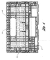
FIGURE 5 illustrates a top plan view of the container ofFigure 1 ; -
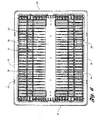
FIGURE 6 is a bottom plan view of the container ofFigure 1 ; -
FIGURE 7 illustrates a perspective view of the base of the container ofFigure 1 ; -
FIGURE 8 is a partial perspective view of a side wall of the container ofFigure 1 ; -
FIGURE 9 is a perspective view of an end wall of the container ofFigure 1 ; -
FIGURE 10 illustrates the container ofFigure 1 with the side walls in an outwardly folded orientation; -
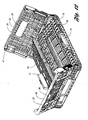
FIGURE 11 illustrates the container ofFigure 1 with the side walls in an inwardly folded orientation, wherein the opposed side walls are first folded inwardly and then the opposed end walls are folded inwardly; -
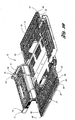
FIGURE 12 illustrates the container ofFigure 1 , wherein the side walls are partially folded inwardly and the end walls are partially folded outwardly; -
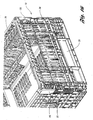
FIGURE 13 illustrates a perspective view of the container shown in the assembled state ofFigure 1 , wherein the assembled container is shown in a stacked orientation with a like container; -
FIGURE 14 is a perspective view of the container in an inwardly folded state as shown inFigure 7 , and which is stacked together in a stacked orientation with a like inwardly folded container; -
FIGURE 15 is a perspective view of a corner portion of the container ofFigure 1 showing a mating adjacent side wall and end wall; -
FIGURE 16 is a perspective view of a corner portion of the container ofFigure 1 showing another mating adjacent side wall and end wall, and shown from a different angle than that inFigure 15 ; -
FIGURE 17 is a perspective view of two like containers according to the present invention which are disposed side-by-side and oriented in a stacked orientation with a single larger container; -
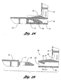
FIGURE 18 is a top plan sectional view of the assembled latching system according to the present invention, and taken along line 16-16 ofFigure 8 , for latching together side walls and end walls, according to the present invention; -
FIGURE 19 is a top plan sectional view of the latching system ofFigure 16 in a disassembled orientation, with the side wall shown separated from the end wall; -
FIGURE 20 is a perspective view of a corner portion ofcontainer 10 according to the present invention; -
FIGURE 21 is a sectional view taken along the line 21-21 ofFigure 20 ; -
FIGURE 22 is a sectional view similar to that shown inFigure 21 , but with the end wall in an outwardly folded orientation; -
FIGURE 23 is a sectional view taken along the line 23-23 ofFigure 20 ; -
FIGURE 24 is a sectional view similar to that shown inFigure 23 , but with the side wall in an outwardly folded orientation; -
FIGURE 25 illustrates a perspective view of a second embodiment of the container according to the present invention; -
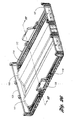
FIGURE 26 illustrates a perspective view of a base of the second embodiment; -
FIGURE 27 illustrates a cross-sectional view of the base taken along the line 27-27 ofFigure 26 ; -
FIGURE 28 illustrates a bottom perspective view of the second embodiment; -
FIGURE 29 illustrates a side elevational view of the second embodiment; -
FIGURE 30 illustrates an end elevational view of the second embodiment; -
FIGURE 31 illustrates a perspective view of the second embodiment, wherein the side and end walls are in an inwardly collapsed position; -
FIGURE 32 illustrates a perspective view of the second embodiment shown inFigure 31 nested on a like container; -
FIGURE 33 illustrates a side elevational view of the inwardly collapsed container ofFigure 31 ; -
FIGURE 34 illustrates a perspective view of the second embodiment of the container as shown inFigure 25 in an assembled orientation, and stacked with a like container; -
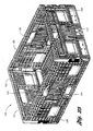
FIGURE 35 illustrates a perspective view showing two containers according to the first embodiment positioned adjacent and stacked on the container according to the second embodiment; and -
FIGURE 36 is a side elevational view of the system shown inFigure 35 . - With reference to
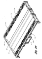
Figure 1 of the drawings, illustrated therein iscollapsible container 10 according to the present invention in an assembled orientation or state. The components ofcontainer 10 are typically formed of various types of plastic or polymeric material by an injection molding or other plastic molding process suitable to this application.Container 10 may be used for the storage and transport of goods, and may also be referred to as a collapsible crate. Whilecontainer 10 is suited for many uses,container 10 is particularly suitable for storing and transporting produce such as fruits and vegetables, where circulation of air and/or refrigerated gas is necessary to keep the produce fresh and consumable while it reaches the market. This circulation is fostered through the plurality ofapertures 11 and other openings provided inbase 12 andwalls entire container 10.Container 10 is generally symmetrical around both its longitudinal and transverse centerlines. -
Container 10 includes abase member 12 having abottom panel 14 which serves as the lower support for the container.Base 12 is best illustrated in the bottom perspective view ofFigure 2 and the base perspective view ofFigure 7 . As is best shown in the top plan view ofFigure 5 and bottom plan view ofFigure 6 ,bottom panel 14 is generally rectangular in shape. With further reference toFigures 1 and6 ,bottom panel 14 has four edges -- namely, a pair of opposed side edges 16 and 18, and a pair of opposed end edges 20 and 22.Base 12 further includes a pair of integrally molded opposedupstanding flanges 24 and 26 (or base walls) oriented perpendicular tobottom panel 14, each defining anupper end edge container 10. - As further illustrated in
Figures 1 ,2 , and7 ,base 12 also includes another pair of opposedupstanding members bottom panel 14 at pair of opposed side edges 16, 18. Whilemembers upstanding members side edge Members container 10 when in the assembled orientation ofFigure 1 .Members more containers 10 which are nested (or stacked) together when in the inwardly folded position, as inFigures 11 and14 . In the orientation ofFigure 14 , the lower container 10' is inwardly folded for receiving anothercontainer 10 thereupon (whetherupper container 10 is folded or assembled). Thus, in this orientation, members |70',|72' receive at least a portion of the top load fromcontainer 10, thereby allowing the top load fromcontainer 10 to be transferred directly to base 12' throughmembers - Moreover,
members container 10, which signify for example the contents of the container, the manufacturer, etc.Members detent 69 disposed on its upper edge which provides a slight interference betweenbase 12 andside walls - As shown in
Figures 1-2 and10-12 ,container 10 also includes a first pair ofopposed side walls bottom panel 14, and a second pair ofopposed side walls Figure 1 , first and second pairs of opposed side walls andbase 12 define acompartment 13 for storing goods therein. - Referring to
Figures 1 ,2 ,3 , and8 ,side walls compartment 13, and have an arcuate shape. Particularly, in the embodiment shown, thecentral portion side walls Side walls base 12 by way of a hinging configuration or system 80 (best shown inFigures 7-8 ), located atedges bottom panel 14. Thus,side walls base 12 atedges Such hinging system 80 allowsside walls Figures 1-2 ; the outwardly collapsible orientation, as illustrated inFigure 10 ; and the inwardly collapsible orientation, as illustrated inFigure 11 . As shown inFigure 2 , hingingsystem 80 does not extend the length ofbase 12 but terminates at a distance away from eachupstanding flange corresponding corner line 31. As best shown inFigures 8 and10 , side walls have a lower recessededge portion corresponding base members Figure 1 . Side walls may also include amating recess 67 for receivingdetent 69 therein during an assembled orientation. - As previous noted and as illustrated in
Figures 1-2 ,4 , and9 ,container 10 further includes a second pair ofopposed side walls opposed end walls side walls end walls central portion end walls side walls end walls base 12 by way of ahinging mechanism 90 which is similar in structure to hingingmechanism 80 described above. However, unlike the side walls, endwalls base 12 at a distance remote frombottom panel 14. Particularly,end walls upstanding flanges base 12, proximateupper edges bottom panel 14. The height of upstandingbase wall flanges end walls bottom panel 14. As with the other walls discussed herein,end walls Figures 1-2 ; outwardly collapsed as inFigure 10 ; and inwardly collapsed as inFigure 11 - The bowed features of the side and end walls generally serves to increase the
interior volume 13 ofcontainer 10, thereby allowingcontainers 10 to store and transport more product. - As best shown in
Figure 9 (and also inFigures 1 and3 ), eachend wall end wall portion 40, and twoshorter flange portions end wall portion 40 and located on either side of mainend wall portion 40.Flange portions end wall portion 40 and, in the assembled orientation ofFigure 1 , are directed inwardly toward the other end wall (32 or 34) andside walls flange portions side walls - Further included in
container 10 is a locking or latching system for latching side walls (28,30) together with end walls (32,34) to achieve the desired stability whencontainer 10 is oriented in the assembled orientation, as illustrated inFigures 8 and10 . With reference toFigure 10 , provided on eachlateral edge side walls latch member 56 extending outwardly therefrom. - By way of example with respect to
Figures 9 and10 , for latching purposes,shorter flanges end walls latch receiving system 58 provided for receivinglatch member 56 therein. Latch receivingsystem 58 includes areceiver member 59,latch receiving aperture 60 and a spring member 62 (or living hinge).Aperture 60 is appropriately sized and shaped to firmly receivelatch member 56.Receiver member 59 is disposedadjacent aperture 60.Receiver member 59 is attached to endwall spring member 62, thus allowing it to be flexible over its length, and particularly actuable in the side to side direction. Thus, as illustrated inFigure 12 , as a side wall (28 or 30) is raised upwardly and an adjacent end wall (32 or 34) is also raised upwardly to receivelatch member 56 into the assembled orientation,aperture 60 slidingly receiveslatch member 56 therein, thereby flexingspring member 62 laterally causingreceiver member 59 to move from its rest position (seeFigure 18 ). - As further illustrated in the top plan sectional views of
Figures 18-19 , and particularly in the final assembled position ofFigure 18 , aprojection member 61 is disposed onreceiver member 59 for being received by a correspondingaperture 57 formed inlatch member 56. During the assembled state,projection 61 retains latchingmember 56 in a secure manner and provides the stability desired for maintainingcontainer 10 in the assembled position. The depth offlanges longer latch member 56 than would otherwise be possible. With further reference toFigures 18 and 19 , in order to collapsecontainer 10 from the assembled orientation into the folded orientations ofFigures 10 and11 , outer release member 55 (accessible from the outside of container 10) ofreceiver member 59 is actuated and moved laterally by the user (its movement shown in phantom inFigure 18 ), andprojection 61 is accordingly raised fromaperture 57 inlatch member 56, allowinglatch member 56 to be released fromlatch receiver 58.Release member 55 is best illustrated inFigures 1 ,4 , and12 . - The reduced stress concentration of the latch mechanism as provided according to the present invention is further illustrated in
Figures 3 and10 . By example, refer generally toline 81 which is formed by the mating lateral edges ofside wall 28 and end wall 32 (for example,line 81 defined bylateral edge 48 ofside wall 28 andflange 42 of end wall 32). The latching that takes place is spaced apart fromcorner line 31 which otherwise is subjected typically to relatively higher stress concentration forces. - Again referring to
Figures 8 and10 , in addition to latchmember 56, eachlateral edge side walls first tab member 45, shown as relatively large and elongated, which projects from a lower portion of its respective edge ofside walls container 10,tab member 45 is received by acorresponding opening 47 which resembles a narrow slot onshorter flanges end walls first tab member 45 in a secure fit for providing a manner by which to align and orient the adjoining walls, as well as secondarily assisting in securely holding side walls (28, 30) and end walls (32, 34) upright together during the assembled orientation. Moreover, upper portion of lateral edges (48, 50) and (52, 54) ofside walls second tab member 49 which is relatively smaller thanfirst tab member 45. Likefirst tab member 45, in the assembled orientationsecond tab member 49 is received by a corresponding tab opening 51 formed inflanges end wall Tab member 49 is provided generally for alignment purposes as well as to provide an additional point of engagement between the adjoining walls. - As illustrated in
Figures 1-4 and8-11 ,container 10 preferably includes a plurality of recesses 17 (or notches) around its perimeter formed in upper container edges. As illustrated inFigure 13 ,container 10 is in an assembled orientation and is stacked with a like container 10' subjacent thereto. Components of container 10' similar to those of thecontainer 10 are correspondingly numbered, with the addition of a prime (') designation.Container 10 is stacked directly above container 10' such that each of its plurality of foot tabs15 are aligned with and are received within corresponding recesses 17' of container 10'. Such alignment betweenfoot tab 15 and recess 17' provides additional stability and alignment tocontainer 10 when in a stacked orientation with like container 10'. - Referring to
Figure 10 ,container 10 is illustrated in an outwardly folded configuration whereinside walls walls container 10. With reference now directed toFigure 11 , shown therein iscontainer 10 havingside walls walls base 12 andbottom panel 14. AsFigures 11 and14 indicate, the design according to the present invention allowscontainer 10 to be compactly folded for storage and transport. In this orientation,side walls mechanism bottom panel 14.Figure 11 illustratesside wall 28 folded first andside wall 30 subsequently folded thereupon. Subsequently endwalls side walls system 90. With reference toFigure 14 and discussed further herein,container 10 may be nested securely with a similar container when in this inwardly folded orientation. Note that when in this orientation,flange portions members - As shown in
Figures 1 and2 , eachend wall hand opening 39 ideally suited to be used as a handle in order to carrycontainer 10. With reference toFigures 1 and2 ,container 10 also includes a plurality of flexiblevertical tabs 93 formed integrally withside walls walls - With regard to hinging systems of
container 10, shown in association with the individual perspective views base 12 ofFigure 7 and the walls ofFigures 8 and9 , are the hinging systems 80 (forside walls 28, 30) and 90 (forend walls 32, 34). Specifically, hingingsystems lower hinge portions base 12 to mate with and attach toupper hinge members Figures 7 ,8 , and9 ). These hinge members are spaced apart generally on each side ofupstanding member upper hinge portions base hinge members base 12. Of course, this type of hinge is shown by way of example and not limitation, as the hinge system utilized may be any type known or contemplated which is feasible for this use. - With further reference to the hinging systems,
base 12 includes at either end ofupstanding flange corner member portion 33 which projects upward pastupper edges upstanding flanges corner portion 33 includes twoopenings corner portion 33 also defines acorner line 31.Opening 19 is located relatively lower andopening 21 is located relatively higher along the height ofcorner portion 33. Each co-linear pair ofopenings 19 is provided to receive a corresponding projection 36 (shown inFigure 8 ) provided at each end of a corresponding side wall (28, 30) for providing an additional pivoting point for each side wall with respect tobase 12. Conversely, each co-linear pair ofopenings 21 share an axis generally adjacent upper surface (25,27) ofupstanding wall Figures 21 and 22 ,openings 21 are provided to receive a corresponding projection 37 (seeFigure 9 ) provided at either end of each end wall (32,34) thereby allowing each end wall to pivot with respect tobase 12. Thusopenings - As illustrated in the sectional views of
Figures 23 and 24 , the lower edge of each side wall may include a relatively small detent 23 (or ridge) which is received in a corresponding channel inbase 12. Referring again toFigures 21 and 22 , the side walls may include aprojection 53 which extends along the edge of the sidewall that mates with and corresponds to cornerportion 33, and is received by amating channel 38. These projections allow for interference between the walls the corresponding base and corner portions, such that when the walls are moving between the assembled and the collapsed orientations, the walls preferably do not fall freely, but instead require assistance from the user (however minimal). Thus, during container assembly, the user does not need to support all four walls when attempting to assemble the container. - As shown in
Figures 1 ,3 , and15 , side walls (28, 30) have aportion 65 that extends intorecess 46 in the corner area and projects outboard beyondedge portion 65 generally provides for a stronger container, in terms of strength-to-weight ratio, particularly during top loading ofcontainer 10. -
Figures 2 and6 illustratebottom surface 63 ofcontainer 10 and illustrate the features which permit nesting ofsimilar containers 10 on top of each other when they are in the inwardly folded orientation (as inFigure 11 ). This design permits an inwardly collapsedcontainer 10 to be stacked on top of a like folded container so that the resulting stack-up is stable (seeFigure 14 ). In an embodiment, this design ofcontainer 10 is also adapted to be positioned side-by-side with a similar container 10' and stacked on top of an assembled larger container 200 (seeFigures 17 and35 - 36 ). Thus, feet 15' onbottom surface 63 ofcontainer 10 are securely received by corresponding openings 202' formed in the upper edge ofcontainer 200. (Larger container 200 may particularly be represented bycontainer 110 disclosed herein.) - With reference to
Figure 14 , illustrated is a perspective view of a pair ofcontainers 10 and 10' according to the present invention which are inwardly folded as shown inFigure 11 and which are in a nested orientation. With further reference toFigure 2 , illustrated is the bottom perspective view ofcontainer 10, such that the features that permit for nesting whencontainer 10 is in the inwardly collapsed state ofFigure 11 are shown. For example inFigure 2 ,bottom surface 63 ofbottom member 14 include a first and secondtransverse recess portions bottom surface 63.Transverse recess portions upper portion end walls Figure 11 . This impedes the lateral movement ofcontainer 10 on container 10' when container 10' is in the inwardly folded state. Similarly,bottom projecting portions bottom surface 63 are received withinrecesses end walls Bottom projecting portion 89 is received within thearea 99 defined betweenupper portions walls Figure 11 . Thus,bottom surface 63 design ofcontainer 10 mates with and accommodates the corresponding outer surface of inwardly folded end walls of subjacent container 10' to provide for a stable and secure nested configuration. In keeping with the present invention, it is fully contemplated thatbottom surface 63 ofbase 12 may be designed to provide the proper rib patterns and recesses to be capable of accommodating various end walls heights. It is also contemplated that there are numerous ways of securely stacking containers according to the present invention and is not limited in any way to the design illustrated. - Referring to
Figures 1 ,11 , and15 ,container 10 also includes a notch orrecess 91 which has a radius and defines a generally angled surface disposed at thecorner line 31 of eachend wall Notch 91 typically receives a nylon strap (not shown) which is used to strapcontainers 10 together securely, generally in an automatic palletizing process. In typical containers withoutnotch 91, the containers may be subject to excessive forced by the pallet strap, wherein the pallet straps may be pulled too tight, causing damage to the container.Notch 91 provides a way to align the strap and provides ease of placement of the strap, such that in the automated palletizing process, the strap will work its way intonotch 91, and reduce the likelihood of damage ofcontainers 10.Notch 91 is also particularly located in an area ofcontainer 10 which has relatively greater strength and stability than other areas of the container in order to withstand the strapping forces (incontainer 10, that area being adjacent the latch mechanism and theflanged portions end walls 32, 34). - With reference to
Figure 25 , illustrated is another embodiment of the container according to the present invention, designated ascontainer 110. Note that those components similar to the first embodiment are designated by a like reference number with the addition of a "1" prefix. As illustrated therein,side walls portions walls portions upstanding members -
Figure 26 illustrates a top perspective view of abase 112 of the second embodiment ofcontainer 110, whileFigure 28 is a bottom perspective view ofbase 112.Figure 27 is a cross-sectional view taken along the line 27-27 ofFigure 26 . Referring to these drawings,base 112 has abottom panel 114 which includes at least one curved portion - and preferably twocurved portions 141, 143 - which extend betweenedges bottom panel 114. This bowed feature ofbottom panel 114 serves to add stability to the container and augment the life of the container, as well as provide protection to the contents of containers stacked therebelow. Particularly, whencontainer 110 is filled or has goods placed therein, the weight of the goods will exert load uponbottom panel 114. Under this load, the bowed design ofbottom panel 114 will tend to cause bottom 114 to flatten. This is desirable in comparison to a container having a typically flat bottom which under the same load described above, will tend to sag and bow downward, thereby, decreasing the container's strength, stability, and life, and also possibly causing damage to the contents of the container therebelow. Also, whencontainer 110 is adapted to store and transport produce such as banana bunches, the bowed feature ofbottom panel 114 is adapted to be received within the claw shape of the banana bunch, thereby providing a more stable transport and more secure packaging of the fruit. -
Figure 29 is a side elevational view ofcontainer 110 in an assembled orientation, as inFigure 25 . As illustrated, like the first embodiment,container 110 also includesnotch 191 for the palletizing straps, and further includes the portion ofside walls corresponding recess 146 in the corner region, proximate the corner hinge connection.Figure 30 is an end elevational view again illustrating features ofend wall 134. -
Figure 31 illustratescontainer 110 in an inwardly folded orientation. AsFigures 31 and32 indicate, the design according to the present invention allowscontainer 110 to be compactly folded for storage and transport. In this orientation,side walls mechanisms 180 and folded in a layered fashion on top ofbottom panel 114.Figure 32 illustrates thatside walls side walls system 190. With reference toFigure 32 and discussed further herein,container 10 may be nested securely with a similar container when in this inwardly folded orientation. For example, in this orientation,feet 115 shown onbase 112 inFigure 28 mates withnotches 181, for example, disposed onmembers base 112 may have various designs which allow it to securely nest with a similar container 110' in the inwardly folded position as inFigure 32 , without departing from the teachings according to the present invention.Figure 33 is a side elevational view ofcontainer 110 in the inwardly folded orientation ofFigures 31-32 . -
Figure 34 is a perspective view ofcontainer 110 in an assembled and stacked orientation with a similar container 110'. As with the inwardly folded orientation,feet 115 ofcontainer 110 are received within corresponding recesses 117' formed in the upper edges of container 110'. -
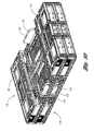
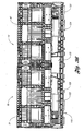
Figure 35 illustrates a perspective view of a stackingsystem 200 showing twocontainers 10 according to the first embodiment positioned side-by-side withside wall 28 of one containeradjacent side wall 30 of the other.Containers 10 are stacked on inwardly foldedcontainer 110 according to the second embodiment.Figure 36 is a side elevational view of the system shown inFigure 35 . As illustrated, whencontainer 110 is folded inwardly, opposedupstanding members upper containers 10 in the gap area betweenshorter end walls containers 10 to be supported over a greater area, and thus providing a more durable stackingsystem 200. This is particularly true when theupper containers 10 are half-size containers as illustrated inFigures 35-36 , and therefore have adjacent portions which meet centrally acrosscontainer 110 and which would not be completely and fully supported without opposedupstanding members containers 10 in this stackingsystem 200 need not be one-half the size of thelower container 110 in order to achieve the objects according to the present invention, but may be anotherfull size container 110. Further, whileFigures 35-36 illustrate thatupper containers 10 are in their assembled positions oncontainer 110,upper containers 10 may also be inwardly collapsed as inFigure 11 according to the teachings of the present invention. Such central support does not otherwise exist in the prior art in containers where the short walls are folded last. - Note that in accordance with the present invention, the features and components illustrated and disclosed in association with the first embodiment may equally apply to the second embodiment, and vice versa.
- It is understood, of course, that while the forms of the invention herein shown and described include the best mode contemplated for carrying out the present invention, they are not intended to illustrate all possible forms thereof. It will also be understood that the words used are descriptive rather than limiting, and that various changes may be made without departing from the scope of the invention as claimed below.
Claims (13)
- A collapsible container (10) comprising:a base (12) having a first pair of opposed upstanding members (70, 72)and a second pair of opposed upstanding members (24, 26); anda pair of upstanding opposed side walls (28, 30) each pivotably attached to the base (12) orientable between an assembled position and a second position;each of the pair of opposed side walls (28, 30) including a cutout portion (71, 73) formed therein for receiving a corresponding one of the pair of upstanding members (70, 72); andthe pair of opposed side walls (28, 30) each further having a pair of opposed lateral edges (48, 50, 52, 54), each lateral edge having a linear portion and a second portion (36) extending outwardly from the lateral edge (48, 50, 52, 54);characterized by
said base (12) including a plurality of upstanding corner members (33) each having a corner recess (19) formed therein;
the second portion (36) received within the corresponding corner recess (19) of the upstanding corner members (33), for enhancing the strength of the container (10). - The collapsible container (10) of claim 1 wherein the container (10) has a second pair of opposed side walls (32, 34) each pivotably attached to a corresponding one of the second pair of opposed upstanding members (24, 26) and orientable between an assembled position and a second position.
- The collapsible container (10) of claim 2, wherein the base (112) includes at least one raised portion (141, 143) extending longitudinally between the second pair of opposed upstanding members (124, 126) and disposed in a central region of the base (112) inward from the base perimeter.
- The collapsible container (10) of claim 2, wherein one of the first and second pair of opposed side walls (28, 30, 32, 34) includes a plurality of recesses (17) adapted to receive a palletizing strap therein when the walls (28, 30, 32, 34) are oriented in the assembled position.
- The collapsible container (10) of claim 2, wherein each of the first pair of opposed side walls (28, 30) includes a latch member (56) disposed thereon for latching the first and second pairs of opposed side walls (28, 30, 32, 34) when oriented in the assembled position.
- The collapsible container (10) of claim 2, wherein each of the second pair of opposed side walls (32, 34) each includes a pair of opposed lateral flanges (42, 44) inwardly depending therefrom and integral therewith, each lateral flange (42, 44) having a latch receiver (58) formed therein.
- The collapsible container (10) of claim 6, wherein in the assembled position and the second position, each lateral flange (42, 44) of the second pair of opposed side walls (32, 34) is substantially co-planar with the first pair of upstanding opposed members (70, 72) of the base (12).
- The collapsible container of claim 6, wherein the latch receiver (58) includes an aperture (60) and a flexible latch spring member (62) and having a latch release member (55) actuable by a user.
- The collapsible container (10) of claim 8, wherein the first pair of opposed side walls (28, 30) includes a pair of opposed lateral edges (48, 50, 52, 54), each lateral edge (48, 50, 52, 54) having a latching member (56) attached thereto,
wherein when the container (10) is oriented in an assembled position, each lateral flange (42, 44) abuts an adjacent lateral edge (48, 50, 52, 54) so that each aperture (60) receives a corresponding latching member (56) which is fastened into position by the latch spring member (62), thereby forming a secure attachment between the first and second pairs of opposed side walls (28, 30, 32, 34), and wherein to return the container (10) to a collapsed position from the assembled position, each latch release member (55) is actuated by the user in order to release the latching member (56) fastened therein. - The collapsible container (10) of claim 2, wherein the base (12) includes a first and second pair of opposed edges (16, 18, 20, 22), the first pair of opposed side walls (28, 30) and the second pair of opposed side walls (32, 34) pivotably attached to a corresponding one of the first and second pair of opposed edges (16, 18, 20, 22).
- The collapsible container (10) of claim 2, wherein the first and second pair of opposed side walls (28, 30, 32, 34) are oriented in the second position, they are oriented in one of an inwardly folded orientation and an outwardly folded orientation.
- The collapsible container (10) of claim 2, wherein the pair of opposed upstanding members (70, 72) are centrally disposed along the length of the base (12),
- The collapsible container (10) of claim 2, wherein the pair of opposed upstanding members (70, 72) have a trapezoidal shape,
Applications Claiming Priority (3)
| Application Number | Priority Date | Filing Date | Title |
|---|---|---|---|
| US473261 | 1999-12-27 | ||
| US09/473,261 US6398054B1 (en) | 1999-12-27 | 1999-12-27 | Collapsible container |
| PCT/US2000/035292 WO2001047778A1 (en) | 1999-12-27 | 2000-12-27 | Collapsible container |
Publications (3)
| Publication Number | Publication Date |
|---|---|
| EP1259434A1 EP1259434A1 (en) | 2002-11-27 |
| EP1259434A4 EP1259434A4 (en) | 2008-09-10 |
| EP1259434B1 true EP1259434B1 (en) | 2012-01-18 |
Family
ID=23878831
Family Applications (1)
| Application Number | Title | Priority Date | Filing Date |
|---|---|---|---|
| EP00988361A Expired - Lifetime EP1259434B1 (en) | 1999-12-27 | 2000-12-27 | Collapsible container |
Country Status (13)
| Country | Link |
|---|---|
| US (3) | US6398054B1 (en) |
| EP (1) | EP1259434B1 (en) |
| JP (1) | JP2003518471A (en) |
| KR (1) | KR20020073155A (en) |
| AR (1) | AR033352A1 (en) |
| AT (1) | ATE541791T1 (en) |
| AU (1) | AU778276B2 (en) |
| BR (1) | BRPI0016806B1 (en) |
| CA (1) | CA2395367C (en) |
| CO (1) | CO5300442A1 (en) |
| HN (1) | HN2000000290A (en) |
| MX (1) | MXPA02006410A (en) |
| WO (1) | WO2001047778A1 (en) |
Families Citing this family (124)
| Publication number | Priority date | Publication date | Assignee | Title |
|---|---|---|---|---|
| JP3981226B2 (en) * | 1999-11-30 | 2007-09-26 | キョーラク株式会社 | container |
| US6386388B1 (en) | 1999-12-27 | 2002-05-14 | Rehrig Pacific Company | Container |
| US6398054B1 (en) * | 1999-12-27 | 2002-06-04 | Rehrig Pacific Co. | Collapsible container |
| USD466300S1 (en) | 2000-03-17 | 2002-12-03 | Arca System Ab | Pallet container |
| USD466690S1 (en) | 2000-03-17 | 2002-12-10 | Arca Systems Ab | Pallet container with a door |
| US6273259B1 (en) | 2000-05-09 | 2001-08-14 | Norseman Plastics Limited | Container |
| JP4585089B2 (en) * | 2000-06-15 | 2010-11-24 | 岐阜プラスチック工業株式会社 | Folding container loading structure |
| DE10041886B4 (en) * | 2000-08-25 | 2007-03-22 | Ifco Systems Gmbh | transport container |
| USD458753S1 (en) | 2000-09-21 | 2002-06-18 | Rehrig Pacific Co. | Container |
| US6631822B1 (en) | 2000-10-28 | 2003-10-14 | Rehrig Pacific Company | Collapsible container |
| US6843386B2 (en) * | 2001-01-15 | 2005-01-18 | Norseman Plastics Limited | Biased latch hinge |
| US7014043B2 (en) * | 2001-01-15 | 2006-03-21 | Norseman Plastics, Limited | Multi-level stacking container |
| US6554529B2 (en) * | 2001-03-05 | 2003-04-29 | Energy Absorption Systems, Inc. | Energy-absorbing assembly for roadside impact attenuator |
| WO2003001890A2 (en) * | 2001-06-28 | 2003-01-09 | Scalise Casey M | Resiliently compressible force absorption system conformable to fruit |
| USD582161S1 (en) * | 2001-09-28 | 2008-12-09 | Design Ideas, Ltd. | Portion of a mesh basket |
| USD461639S1 (en) | 2001-10-09 | 2002-08-20 | Pablo Francisco Wenborne | Container |
| US7104414B2 (en) | 2002-01-12 | 2006-09-12 | Rehrig Pacific Company | Collapsible container |
| US6863180B2 (en) * | 2002-02-15 | 2005-03-08 | Rehrig Pacific Company | Collapsible container |
| NL1020042C2 (en) * | 2002-02-22 | 2003-08-27 | Vika Metaal B V | Collapsible container, has front wall sloping away from base and back and side walls extending perpendicular to base |
| US7478726B2 (en) * | 2002-05-28 | 2009-01-20 | Rehrig Pacific Company | Collapsibile crate with support members |
| USD474890S1 (en) | 2002-08-12 | 2003-05-27 | Contenedores Plasticos S.A. | Crate |
| US7059489B2 (en) * | 2002-10-11 | 2006-06-13 | Rehrig Pacific Company | Portable storage device |
| US7637373B2 (en) * | 2003-01-24 | 2009-12-29 | Norseman Plastics, Ltd | Stackable container |
| US7017766B2 (en) * | 2003-03-10 | 2006-03-28 | Rehrig Pacific Company | Collapsible container with side wall latching capability |
| US7100786B2 (en) * | 2003-03-21 | 2006-09-05 | Rehrig Pacific Company | Collapsible container |
| US20050077217A1 (en) * | 2003-03-28 | 2005-04-14 | Hillerich Thomas A. | Carrier for mail and/or the like thin objects |
| MXJL03000014A (en) * | 2003-04-22 | 2004-10-29 | Alejandro Betancourt Ruelas | Folding crate. |
| US6868979B2 (en) | 2003-05-08 | 2005-03-22 | Monoflo International, Inc. | Collapsible plastic container with locking feature |
| US7195127B2 (en) * | 2003-05-13 | 2007-03-27 | Rehrig Pacific Company | Collapsible container |
| DE10326574B4 (en) * | 2003-06-12 | 2007-09-27 | Ifco Systems Gmbh | Transport container system and attachment for a transport container system for general cargo, in particular for fruit and vegetables |
| USD505262S1 (en) * | 2003-06-13 | 2005-05-24 | Pedro Chinni | Crate |
| US20050155967A1 (en) * | 2004-01-21 | 2005-07-21 | Vial Ignacio B. | Locking arrangements for side walls of rigid, foldable or collapsible boxes |
| US7475526B2 (en) * | 2004-04-19 | 2009-01-13 | Polymer Logistics (Israel) Ltd. | Knock-down crate with walls stored in base and method employing such a crate |
| WO2005100176A2 (en) * | 2004-04-19 | 2005-10-27 | Polymer Logistics (Israel) Ltd. | Knock-down crate with walls stored in base and method employing such a crate |
| US20070199934A1 (en) * | 2004-07-19 | 2007-08-30 | Warwick Michael J | Container |
| US20060054528A1 (en) * | 2004-08-30 | 2006-03-16 | Sanzana Cecil M | Foldable plastic box, assemblable, having 5 cavities, with or without folding upper covers, to contain agricultural products |
| DE202005016115U1 (en) * | 2004-11-16 | 2006-04-06 | Fritz Schäfer GmbH | Storage, transport, stacking and picking containers |
| USD519736S1 (en) * | 2004-11-22 | 2006-05-02 | Jones David M | Crate |
| US7353950B2 (en) * | 2004-12-06 | 2008-04-08 | Norseman Plastics, Ltd. | Container |
| USD539541S1 (en) | 2005-05-27 | 2007-04-03 | Stahl Edward L | Three level nesting/stacking containers |
| WO2006132613A1 (en) * | 2005-06-03 | 2006-12-14 | Linpac Materials Handling | Container assembly and latch apparatus, and related methods |
| US20070095825A1 (en) * | 2005-10-28 | 2007-05-03 | Hui-Lan Tsao | Foldable-type storage box |
| US20070095842A1 (en) * | 2005-11-01 | 2007-05-03 | Apps William P | Container |
| US7357269B2 (en) * | 2005-11-01 | 2008-04-15 | Rehrig Pacific Company | Container |
| USD598684S1 (en) | 2005-12-01 | 2009-08-25 | Norseman Plastics Ltd. | Multi-level sliding stacking container |
| US8047369B2 (en) * | 2005-12-01 | 2011-11-01 | Orbis Canada Limited | Breadbasket with merchandiser window and flaps |
| US20070145052A1 (en) * | 2005-12-28 | 2007-06-28 | Steinhauser Mark R | Collapsible package, and methods |
| USD553858S1 (en) * | 2006-02-09 | 2007-10-30 | Odesa Gelistirilmis Polimer Yatirimlari Ve Dis Ticaret Anonim Sirketi | Foldable crate |
| US20070272579A1 (en) * | 2006-05-24 | 2007-11-29 | Rehrig Pacific Company | Collapsible crate with support members |
| WO2008013574A2 (en) | 2006-07-27 | 2008-01-31 | Norseman Plastics Ltd. | Tray with drain channels and scalloped handles |
| US20080116201A1 (en) * | 2006-11-17 | 2008-05-22 | Kyle Baltz | Container |
| US7686167B1 (en) | 2006-12-14 | 2010-03-30 | Orbis Canada Limited | Stackable container with front and rear windows, and method for using the same |
| US7784615B2 (en) * | 2007-05-30 | 2010-08-31 | Orbis Canada Limited | Nestable and stackable container for the transport of heavy baked items |
| US7641066B2 (en) * | 2007-06-11 | 2010-01-05 | Rehrig Pacific Company | Collapsible container |
| US7717283B2 (en) | 2007-11-06 | 2010-05-18 | Rehrig Pacific Company | Collapsible container |
| US8261923B2 (en) * | 2008-04-22 | 2012-09-11 | Otto Industries North America, Inc. | Collapsible container |
| US7861879B2 (en) | 2008-05-02 | 2011-01-04 | Orbis Corporation | Folding container |
| JP2010030657A (en) * | 2008-07-30 | 2010-02-12 | Gifu Plast Ind Co Ltd | Storing box |
| DE102009049185A1 (en) | 2009-04-15 | 2011-01-05 | Ifco Systems Gmbh | Crate with foldable side walls with stable sidewall structure |
| DE102009049184A1 (en) | 2009-04-15 | 2010-11-04 | Ifco Systems Gmbh | Crate with foldable side walls and locking mechanisms with overload protection |
| DE102009049103A1 (en) | 2009-04-15 | 2010-11-04 | Ifco Systems Gmbh | Crate with foldable and removable outer walls |
| RU2509699C2 (en) | 2009-04-15 | 2014-03-20 | ИФЦО Системс Гмбх | Container with folding sidewall |
| ATE520609T1 (en) * | 2009-05-08 | 2011-09-15 | Schoeller Arca Systems Gmbh | CONTAINER, ESPECIALLY FOR THE PRODUCTION AND STORAGE OF WINE AND FRUIT GUM, ETC. |
| USD653451S1 (en) * | 2009-07-24 | 2012-02-07 | Elvinco Technologies Inc. | Bin |
| JP5322907B2 (en) * | 2009-12-02 | 2013-10-23 | 三甲株式会社 | Stacking structure of collapsible folding container and SN container |
| US8413831B2 (en) | 2009-12-16 | 2013-04-09 | Orbis Corporation | Collapsible bin |
| US8770421B2 (en) * | 2010-01-28 | 2014-07-08 | Nova Chemicals (International) S.A. | Collapsible refuse bin |
| US20110192841A1 (en) * | 2010-02-05 | 2011-08-11 | Standfield Laranard Hunter | Folding trash can |
| USD707547S1 (en) * | 2010-03-17 | 2014-06-24 | Ifco Systems Gmbh | Egg crate |
| BR112012025094B1 (en) * | 2010-03-30 | 2019-09-24 | Ifco Systems Gmbh | FOLDING BOX AND ARRANGEMENT OF A PLURALITY OF BOXES |
| ES2511365T3 (en) * | 2010-03-30 | 2014-10-22 | Ifco Systems Gmbh | Box |
| PL2371727T3 (en) * | 2010-03-30 | 2016-06-30 | Ifco Systems Gmbh | Crate |
| DK2371725T3 (en) * | 2010-03-30 | 2013-02-18 | Ifco Systems Gmbh | Box |
| CN102971224B (en) * | 2010-03-30 | 2016-05-25 | 埃弗科系统有限公司 | crate |
| US8978921B2 (en) | 2010-03-30 | 2015-03-17 | Ifco Systems Gmbh | Crate |
| EP2371726A1 (en) * | 2010-03-30 | 2011-10-05 | IFCO Systems GmbH | Crate |
| USD628801S1 (en) | 2010-04-15 | 2010-12-14 | Ipl Inc. | Tote box |
| CA2741242C (en) | 2010-05-27 | 2019-01-15 | Rehrig Pacific Company | Dual height collapsible container |
| DE102011013346B4 (en) * | 2011-03-04 | 2015-05-28 | Georg Utz Holding Ag | collars |
| US9469470B2 (en) | 2011-03-24 | 2016-10-18 | Orbis Corporation | Three tiered tray |
| US20120285951A1 (en) * | 2011-05-11 | 2012-11-15 | Cavalcante Mauricio D | Collapsible crate |
| CN102915092A (en) * | 2011-08-05 | 2013-02-06 | 鸿富锦精密工业(深圳)有限公司 | Fake hard disk and electric device applying same |
| US8651309B2 (en) | 2011-12-21 | 2014-02-18 | Jorge Ibarra | Collapsible container |
| USD702826S1 (en) * | 2012-02-22 | 2014-04-15 | Middle Atlantic Products, Inc. | Electronics mounting plate with a universal hole pattern |
| GB201205243D0 (en) | 2012-03-26 | 2012-05-09 | Kraft Foods R & D Inc | Packaging and method of opening |
| USD684368S1 (en) * | 2012-10-08 | 2013-06-18 | International Precision Components Corporation | Crate |
| US8915397B2 (en) | 2012-11-01 | 2014-12-23 | Orbis Corporation | Bulk container with center support between drop door and side wall |
| USD766575S1 (en) | 2013-01-25 | 2016-09-20 | Georgia-Pacific Corrugated Llc | Bliss container |
| USD765978S1 (en) | 2013-01-25 | 2016-09-13 | Georgia-Pacific Corrugated Llc | Bliss container |
| GB2511560B (en) | 2013-03-07 | 2018-11-14 | Mondelez Uk R&D Ltd | Improved Packaging and Method of Forming Packaging |
| GB2511559B (en) | 2013-03-07 | 2018-11-14 | Mondelez Uk R&D Ltd | Improved Packaging and Method of Forming Packaging |
| US9708097B2 (en) | 2013-11-15 | 2017-07-18 | Orbis Corporation | Bulk bin with integrated shock absorber |
| US9487326B2 (en) | 2013-11-26 | 2016-11-08 | Orbis Corporation | Bulk bin with panel to panel interlock features |
| WO2015195927A1 (en) | 2014-06-20 | 2015-12-23 | Orbis Corporation | Hinge rod trap for a collapsible bin |
| US10138019B2 (en) | 2014-07-12 | 2018-11-27 | Rehrig Pacific Company | Bakery tray assembly |
| US9745100B2 (en) * | 2014-08-27 | 2017-08-29 | Rehrig Pacific Company | Stack and fold dairy shelves |
| WO2016163965A1 (en) * | 2015-04-07 | 2016-10-13 | Karakullukcu Cem Durmus | Folding case with protected locking mechanism |
| EP3286097B2 (en) | 2015-04-07 | 2024-10-02 | Karakullukcu, Cem Durmus | Folding case with protected locking mechanism |
| USD816997S1 (en) | 2015-11-23 | 2018-05-08 | Macro Plastics, Inc. | Shipping container |
| CA2960500A1 (en) | 2016-03-11 | 2017-09-11 | Rehrig Pacific Company | Collapsible crate with wood appearance |
| USD801686S1 (en) * | 2016-04-27 | 2017-11-07 | Inpack Global Co., Ltd. | Folding container |
| USD801688S1 (en) * | 2016-04-29 | 2017-11-07 | Clevermade, Llc | Crate |
| ITUA20164692A1 (en) * | 2016-06-27 | 2017-12-27 | Seko Spa | FOLDING SHELF FOR STORAGE |
| USD802926S1 (en) * | 2016-08-31 | 2017-11-21 | Macro Plastics, Inc. | Shipping container |
| US10065763B2 (en) | 2016-09-15 | 2018-09-04 | Arena Packaging, Llc | Wall latching system |
| USD803015S1 (en) * | 2016-09-28 | 2017-11-21 | Helen Of Troy Limited | Fruit and vegetable basket |
| DE202016106088U1 (en) * | 2016-10-28 | 2017-02-06 | Georg Utz Holding Ag | Collapsible container |
| USD859836S1 (en) * | 2018-02-05 | 2019-09-17 | Georg Utz Holding Ag | Stacking crate |
| US12448172B2 (en) | 2018-03-05 | 2025-10-21 | Rehrig Pacific Company | Collapsible container |
| USD844988S1 (en) * | 2018-03-31 | 2019-04-09 | Creative Plastic Concepts, Llc | Foldable crate |
| US10894631B2 (en) | 2018-03-31 | 2021-01-19 | Creative Plastic Concepts, Llc | Foldable crate |
| CN108860921B (en) * | 2018-08-08 | 2020-11-20 | 上海鸿研物流技术有限公司 | collapsible container |
| US11597557B2 (en) | 2018-10-04 | 2023-03-07 | Rehrig Pacific Company | Reconfigurable beverage crate |
| PL3743344T3 (en) * | 2019-04-04 | 2022-05-16 | Unipas, Spol. S.R.O. | Transport folding container |
| USD919296S1 (en) * | 2019-05-31 | 2021-05-18 | Keter Plastic Ltd. | Crate |
| US20230017541A1 (en) * | 2019-12-11 | 2023-01-19 | Direct Pack, Inc. | Produce trays and related methods |
| USD961930S1 (en) * | 2020-09-09 | 2022-08-30 | Won Seok SONG | Folding box |
| US20220089315A1 (en) * | 2020-09-21 | 2022-03-24 | Rehrig Pacific Company | Collapsible crate |
| USD933364S1 (en) * | 2020-12-03 | 2021-10-19 | Xiufeng Chen | Folding basket |
| USD941582S1 (en) * | 2021-06-30 | 2022-01-25 | Afl Telecommunications Llc | Foldable utility enclosure |
| CA3172382A1 (en) | 2021-09-16 | 2023-03-16 | Rehrig Pacific Company | Hybrid collapsible crate |
| US12054313B2 (en) | 2021-12-15 | 2024-08-06 | Orbis Corporation | Tote with side wall drain holes |
| USD985387S1 (en) * | 2022-06-07 | 2023-05-09 | Sa{hacek over (s)}o Sev{hacek over (s)}ek | Packaging box |
| USD1028521S1 (en) | 2022-08-25 | 2024-05-28 | Tw America Inc. | Storage basket |
Family Cites Families (74)
| Publication number | Priority date | Publication date | Assignee | Title |
|---|---|---|---|---|
| US3446415A (en) | 1967-04-05 | 1969-05-27 | United States Steel Corp | Blanks for ready erection into box-like containers |
| US3513789A (en) * | 1967-11-14 | 1970-05-26 | Samuel J Foose Jr | Seed planting mechanism |
| US3628683A (en) | 1969-11-20 | 1971-12-21 | Wolfgang Erhard Friedrich | Collapsible box |
| US3973692A (en) | 1973-08-23 | 1976-08-10 | Nosco Plastics, Inc. | Injection molded folding box |
| US3874546A (en) * | 1973-10-11 | 1975-04-01 | Pinckney Molded Plastic Inc | Convertible container-pallet |
| JPS5065900U (en) | 1973-10-11 | 1975-06-13 | ||
| US4062467A (en) | 1974-07-27 | 1977-12-13 | Friedrich Wolfgang E | Collapsible transport container |
| ZA746647B (en) | 1974-10-18 | 1976-05-26 | Plastipak Pty Ltd | Collapsible container |
| US4049284A (en) | 1976-04-26 | 1977-09-20 | Ronald Capper | Combination hand truck and garden cart |
| US4044910A (en) | 1976-05-05 | 1977-08-30 | Box Theodor | Collapsible crate |
| GB1529485A (en) | 1976-08-12 | 1978-10-18 | Worldwide Plastics Dev | Collapsible container |
| DE2734964C2 (en) | 1977-08-03 | 1983-08-18 | Uwe Wolfgang 4444 Bentheim Friedrich | Collapsible transport box |
| DE2737867A1 (en) | 1977-08-23 | 1979-03-08 | Spumalit Anstalt | COLLAPSIBLE STACKABLE PLASTIC TRANSPORT BOX |
| US4170313A (en) | 1977-12-29 | 1979-10-09 | Caves Robert B | Box and blank for forming the box |
| US4300695A (en) | 1979-11-30 | 1981-11-17 | Hsu Te Chi | Folding container |
| US4349120A (en) | 1981-06-10 | 1982-09-14 | Bay State Plastics Corp. | Plastic box hinge |
| GB8314141D0 (en) | 1983-05-21 | 1983-06-29 | Paxton Ltd C G | Hinges |
| GB8420962D0 (en) | 1984-08-17 | 1984-09-19 | Rosenorn E | Crate |
| FR2570429B1 (en) | 1984-09-19 | 1986-12-05 | Plastic Omnium Cie | INVIOLABLE HINGE DEVICE, PARTICULARLY FOR THE ARTICULATED MOUNTING OF A COVER ON A ROLLING TRAY TANK |
| US4591065A (en) * | 1984-09-25 | 1986-05-27 | Foy Dennis M | Foldable container assembly |
| CA1225941A (en) * | 1985-01-22 | 1987-08-25 | Larry R. Hughes | Collapsible shipping container |
| US4674647A (en) | 1985-06-21 | 1987-06-23 | Xytec Plastics, Inc. | Collapsible storage bin |
| US4741032A (en) | 1986-03-17 | 1988-04-26 | Siecor Corporation | Container for telephone network interface device |
| US4663803A (en) | 1986-04-15 | 1987-05-12 | Menasha Corporation | Security hinge joint with separate hinge pin |
| IT208670Z2 (en) | 1986-09-16 | 1988-05-28 | Mass Plast Snc Di Ferraroni E | CONTAINER-CLASSIFIER FOR FLAT OBJECTS, IN PARTICULAR FOR SMALL COMPUTER DISCS |
| US4735330A (en) * | 1987-03-02 | 1988-04-05 | Chrysler Motors Corporation | Collapsible bin |
| US4923079A (en) | 1987-03-06 | 1990-05-08 | Ropak Corporation | Collapsible container |
| US4735331A (en) | 1987-04-06 | 1988-04-05 | Chrysler Motors Corporation | Collapsible bin |
| US4781300A (en) | 1987-04-16 | 1988-11-01 | Long Florence M | Folding basket for laundry and other uses |
| USD306264S (en) | 1987-08-03 | 1990-02-27 | Xytec Plastics, Inc. | Container with lid |
| US4765480A (en) | 1987-08-03 | 1988-08-23 | Xytec Plastics, Inc. | Container with collapsible lid members |
| US4846089A (en) | 1987-08-27 | 1989-07-11 | Tempress Incorporated | Hatch with releasable hinge assembly |
| US5038953A (en) | 1987-10-08 | 1991-08-13 | Monoflo International, Inc. | Collapsible box |
| US4775068A (en) | 1988-01-11 | 1988-10-04 | Xytec Plastics, Inc. | Collapsible container with removable access panel |
| US4809874A (en) | 1988-02-26 | 1989-03-07 | Pehr Harold T | Hinged closure for containers |
| US4940155A (en) | 1988-03-14 | 1990-07-10 | Hewson Kenneth E | Collapsible container |
| US4887747A (en) | 1988-06-08 | 1989-12-19 | Seaquist Closures, A Division Of Pittway Corporation | Two-piece, snap-action closure |
| US5161709A (en) | 1989-01-30 | 1992-11-10 | World Container Corporation | Hinged collapsible container |
| US4917255A (en) * | 1989-02-24 | 1990-04-17 | J.I.T. Corporation | Collapsible container |
| US4967927A (en) | 1989-03-15 | 1990-11-06 | Xytec, Inc. | Container with latchable hinged sidewall gate |
| US5076457A (en) | 1989-06-22 | 1991-12-31 | Tetra Pak Holdings S.A. | Folding crate for holding packages |
| US4960223A (en) | 1989-07-18 | 1990-10-02 | Chiang Pei Lieh | Box crate container |
| US5048715A (en) | 1989-09-07 | 1991-09-17 | Dart Industries, Inc. | Closure assembly with hinged cover |
| US4979634A (en) | 1990-01-02 | 1990-12-25 | Cooper Industries, Inc. | Hold-open hinge mechanism for a molded plastic cover |
| US5114037A (en) | 1990-06-19 | 1992-05-19 | Perstorp Xytec, Inc. | Container with sidewall extension |
| US5183180A (en) | 1990-12-03 | 1993-02-02 | Otto Industries, Inc. | Plastic refuse container |
| US5289935A (en) | 1991-05-14 | 1994-03-01 | Perstorp Xytec, Inc. | Container with sidewall extension and method for making |
| DE4201145C2 (en) | 1992-01-17 | 2001-02-08 | Giso Verwaltungsgmbh & Co Beha | Containers made of plastic, in particular vegetable containers, with foldable side walls |
| AT401765B (en) | 1992-11-18 | 1996-11-25 | Furtner Josef | CONTAINER WITH SWIVELING SIDEWALLS |
| US5328048A (en) | 1993-02-08 | 1994-07-12 | Otto Industries, Inc. | Tote box |
| CA2095095A1 (en) | 1993-04-28 | 1994-10-29 | Michel Lanoue | Plastic container with hinged lids |
| US5474197A (en) | 1993-12-27 | 1995-12-12 | Perstorp Xytec | Collapsible container with reduced deflection |
| WO1995018047A1 (en) | 1993-12-30 | 1995-07-06 | Hae Soon Oh | Folding and unfolding box |
| US5474200A (en) | 1994-05-06 | 1995-12-12 | Otto Industries, Inc. | Lidded container having security hinge |
| JPH10506868A (en) | 1994-10-07 | 1998-07-07 | ショーラー インターナショナル エンジニアリング ソシエテ アノニム | Collapsible plastic container |
| MX9605795A (en) * | 1995-03-22 | 1997-12-31 | Ladislav Stephan Karpisek | Collapsible pallet with side walls hinged to the base by links. |
| DE19518955A1 (en) | 1995-05-23 | 1996-11-28 | Schoeller Plast Ag | Puncture-proof wall construction |
| US5622276A (en) | 1995-06-01 | 1997-04-22 | Simmons; John M. | Collapsible container/cooler apparatus |
| CA2153141C (en) | 1995-06-30 | 1998-10-06 | Roch Nolet | Five-piece container having foldable side pieces |
| GB2303616B (en) * | 1995-07-26 | 1999-09-15 | Mckechnie Uk Ltd | Collapsible container |
| USD387557S (en) | 1995-08-28 | 1997-12-16 | Perstorp Ab | Transport container with flap doors |
| AU128271S (en) | 1995-10-18 | 1996-10-10 | Perstorp Ab | Collapsible container |
| EP0857144A1 (en) | 1995-10-26 | 1998-08-12 | Schoeller International Engineering S.A. | Collapsible plastic container |
| CA2180811C (en) | 1996-07-09 | 2002-07-30 | Michel Jacques | Five-piece container with hingeable sides |
| US5699926A (en) | 1996-08-13 | 1997-12-23 | Ipl, Inc. | Five-piece container with stabilizer tablet |
| CA2202119C (en) | 1997-04-08 | 2000-05-23 | Ipl Inc. | Five-piece open container with locking arrangement |
| US5881880A (en) | 1997-10-23 | 1999-03-16 | Ipl, Inc. | Nestable lid |
| US6015056A (en) | 1997-12-19 | 2000-01-18 | Rehrig Pacific Company | Collapsible container |
| AU136959S (en) | 1998-03-13 | 1999-04-06 | Perstorp Plastic Syst Ab | Transport container |
| USD423217S (en) | 1998-09-10 | 2000-04-25 | Perstorp Plastics Systems Ab | Transport container III |
| US6386388B1 (en) | 1999-12-27 | 2002-05-14 | Rehrig Pacific Company | Container |
| US6398054B1 (en) | 1999-12-27 | 2002-06-04 | Rehrig Pacific Co. | Collapsible container |
| US6405888B1 (en) | 2000-02-12 | 2002-06-18 | Rehrig Pacific Company | Collapsible container |
| US6460717B1 (en) | 2001-08-29 | 2002-10-08 | Rehrig Pacific Company | Inwardly folding container |
-
1999
- 1999-12-27 US US09/473,261 patent/US6398054B1/en not_active Expired - Lifetime
-
2000
- 2000-06-27 US US29/125,652 patent/USD446392S1/en not_active Expired - Lifetime
- 2000-12-26 AR ARP000106925A patent/AR033352A1/en unknown
- 2000-12-26 HN HN2000000290A patent/HN2000000290A/en unknown
- 2000-12-27 KR KR1020027008373A patent/KR20020073155A/en not_active Withdrawn
- 2000-12-27 WO PCT/US2000/035292 patent/WO2001047778A1/en not_active Ceased
- 2000-12-27 EP EP00988361A patent/EP1259434B1/en not_active Expired - Lifetime
- 2000-12-27 JP JP2001548336A patent/JP2003518471A/en active Pending
- 2000-12-27 AT AT00988361T patent/ATE541791T1/en active
- 2000-12-27 AU AU24575/01A patent/AU778276B2/en not_active Ceased
- 2000-12-27 CO CO00097836A patent/CO5300442A1/en not_active Application Discontinuation
- 2000-12-27 CA CA002395367A patent/CA2395367C/en not_active Expired - Fee Related
- 2000-12-27 MX MXPA02006410A patent/MXPA02006410A/en active IP Right Grant
- 2000-12-27 BR BRPI0016806A patent/BRPI0016806B1/en not_active IP Right Cessation
-
2002
- 2002-06-03 US US10/163,004 patent/US7044319B2/en not_active Expired - Lifetime
Also Published As
| Publication number | Publication date |
|---|---|
| CA2395367C (en) | 2008-10-28 |
| USD446392S1 (en) | 2001-08-14 |
| AU2457501A (en) | 2001-07-09 |
| CO5300442A1 (en) | 2003-07-31 |
| HN2000000290A (en) | 2001-07-09 |
| WO2001047778A1 (en) | 2001-07-05 |
| AU778276B2 (en) | 2004-11-25 |
| EP1259434A1 (en) | 2002-11-27 |
| AR033352A1 (en) | 2003-12-17 |
| CA2395367A1 (en) | 2001-07-05 |
| EP1259434A4 (en) | 2008-09-10 |
| US7044319B2 (en) | 2006-05-16 |
| US6398054B1 (en) | 2002-06-04 |
| BRPI0016806B1 (en) | 2016-03-29 |
| BR0016806A (en) | 2002-12-24 |
| ATE541791T1 (en) | 2012-02-15 |
| JP2003518471A (en) | 2003-06-10 |
| KR20020073155A (en) | 2002-09-19 |
| US20020158067A1 (en) | 2002-10-31 |
| MXPA02006410A (en) | 2003-02-12 |
Similar Documents
| Publication | Publication Date | Title |
|---|---|---|
| US6398054B1 (en) | Collapsible container | |
| US7017765B2 (en) | Container | |
| US6601724B1 (en) | Collapsible merchandizing container | |
| CA2397522C (en) | Mutli-purpose container | |
| CA2421595C (en) | Container | |
| US7234599B2 (en) | Portable storage container | |
| US6296118B1 (en) | Stackable, nestable, and reusable container for storing and dispensing elongated materials, and method of using same | |
| EP1341699B1 (en) | Collapsible container | |
| US8672161B2 (en) | Nestable display crate for bottle carriers | |
| EP0211116B1 (en) | Collapsible storage bin | |
| US20100326871A1 (en) | Tray | |
| AU2007221738B2 (en) | Collapsible container | |
| AU2004218733B2 (en) | Collapsible container | |
| AU774721B2 (en) | Stackable folding container | |
| MXPA00011355A (en) | Collapsible merchandising container |
Legal Events
| Date | Code | Title | Description |
|---|---|---|---|
| PUAI | Public reference made under article 153(3) epc to a published international application that has entered the european phase |
Free format text: ORIGINAL CODE: 0009012 |
|
| 17P | Request for examination filed |
Effective date: 20020705 |
|
| AK | Designated contracting states |
Kind code of ref document: A1 Designated state(s): AT BE CH CY DE DK ES FI FR GB GR IE IT LI LU MC NL PT SE TR |
|
| AX | Request for extension of the european patent |
Free format text: AL;LT;LV;MK;RO;SI |
|
| A4 | Supplementary search report drawn up and despatched |
Effective date: 20080812 |
|
| 17Q | First examination report despatched |
Effective date: 20090210 |
|
| GRAP | Despatch of communication of intention to grant a patent |
Free format text: ORIGINAL CODE: EPIDOSNIGR1 |
|
| GRAS | Grant fee paid |
Free format text: ORIGINAL CODE: EPIDOSNIGR3 |
|
| GRAA | (expected) grant |
Free format text: ORIGINAL CODE: 0009210 |
|
| AK | Designated contracting states |
Kind code of ref document: B1 Designated state(s): AT BE CH CY DE DK ES FI FR GB GR IE IT LI LU MC NL PT SE TR |
|
| REG | Reference to a national code |
Ref country code: GB Ref legal event code: FG4D |
|
| REG | Reference to a national code |
Ref country code: CH Ref legal event code: EP |
|
| REG | Reference to a national code |
Ref country code: AT Ref legal event code: REF Ref document number: 541791 Country of ref document: AT Kind code of ref document: T Effective date: 20120215 Ref country code: IE Ref legal event code: FG4D |
|
| REG | Reference to a national code |
Ref country code: DE Ref legal event code: R082 Ref document number: 60046853 Country of ref document: DE |
|
| REG | Reference to a national code |
Ref country code: DE Ref legal event code: R096 Ref document number: 60046853 Country of ref document: DE Effective date: 20120315 |
|
| REG | Reference to a national code |
Ref country code: NL Ref legal event code: VDEP Effective date: 20120118 |
|
| PG25 | Lapsed in a contracting state [announced via postgrant information from national office to epo] |
Ref country code: NL Free format text: LAPSE BECAUSE OF FAILURE TO SUBMIT A TRANSLATION OF THE DESCRIPTION OR TO PAY THE FEE WITHIN THE PRESCRIBED TIME-LIMIT Effective date: 20120118 Ref country code: BE Free format text: LAPSE BECAUSE OF FAILURE TO SUBMIT A TRANSLATION OF THE DESCRIPTION OR TO PAY THE FEE WITHIN THE PRESCRIBED TIME-LIMIT Effective date: 20120118 |
|
| PG25 | Lapsed in a contracting state [announced via postgrant information from national office to epo] |
Ref country code: FI Free format text: LAPSE BECAUSE OF FAILURE TO SUBMIT A TRANSLATION OF THE DESCRIPTION OR TO PAY THE FEE WITHIN THE PRESCRIBED TIME-LIMIT Effective date: 20120118 Ref country code: PT Free format text: LAPSE BECAUSE OF FAILURE TO SUBMIT A TRANSLATION OF THE DESCRIPTION OR TO PAY THE FEE WITHIN THE PRESCRIBED TIME-LIMIT Effective date: 20120518 Ref country code: GR Free format text: LAPSE BECAUSE OF FAILURE TO SUBMIT A TRANSLATION OF THE DESCRIPTION OR TO PAY THE FEE WITHIN THE PRESCRIBED TIME-LIMIT Effective date: 20120419 |
|
| REG | Reference to a national code |
Ref country code: AT Ref legal event code: MK05 Ref document number: 541791 Country of ref document: AT Kind code of ref document: T Effective date: 20120118 |
|
| PG25 | Lapsed in a contracting state [announced via postgrant information from national office to epo] |
Ref country code: CY Free format text: LAPSE BECAUSE OF FAILURE TO SUBMIT A TRANSLATION OF THE DESCRIPTION OR TO PAY THE FEE WITHIN THE PRESCRIBED TIME-LIMIT Effective date: 20120118 |
|
| PG25 | Lapsed in a contracting state [announced via postgrant information from national office to epo] |
Ref country code: DK Free format text: LAPSE BECAUSE OF FAILURE TO SUBMIT A TRANSLATION OF THE DESCRIPTION OR TO PAY THE FEE WITHIN THE PRESCRIBED TIME-LIMIT Effective date: 20120118 Ref country code: SE Free format text: LAPSE BECAUSE OF FAILURE TO SUBMIT A TRANSLATION OF THE DESCRIPTION OR TO PAY THE FEE WITHIN THE PRESCRIBED TIME-LIMIT Effective date: 20120118 |
|
| PLBE | No opposition filed within time limit |
Free format text: ORIGINAL CODE: 0009261 |
|
| STAA | Information on the status of an ep patent application or granted ep patent |
Free format text: STATUS: NO OPPOSITION FILED WITHIN TIME LIMIT |
|
| PG25 | Lapsed in a contracting state [announced via postgrant information from national office to epo] |
Ref country code: IT Free format text: LAPSE BECAUSE OF FAILURE TO SUBMIT A TRANSLATION OF THE DESCRIPTION OR TO PAY THE FEE WITHIN THE PRESCRIBED TIME-LIMIT Effective date: 20120118 |
|
| 26N | No opposition filed |
Effective date: 20121019 |
|
| PG25 | Lapsed in a contracting state [announced via postgrant information from national office to epo] |
Ref country code: AT Free format text: LAPSE BECAUSE OF FAILURE TO SUBMIT A TRANSLATION OF THE DESCRIPTION OR TO PAY THE FEE WITHIN THE PRESCRIBED TIME-LIMIT Effective date: 20120118 |
|
| REG | Reference to a national code |
Ref country code: DE Ref legal event code: R097 Ref document number: 60046853 Country of ref document: DE Effective date: 20121019 |
|
| PG25 | Lapsed in a contracting state [announced via postgrant information from national office to epo] |
Ref country code: ES Free format text: LAPSE BECAUSE OF FAILURE TO SUBMIT A TRANSLATION OF THE DESCRIPTION OR TO PAY THE FEE WITHIN THE PRESCRIBED TIME-LIMIT Effective date: 20120429 |
|
| PG25 | Lapsed in a contracting state [announced via postgrant information from national office to epo] |
Ref country code: MC Free format text: LAPSE BECAUSE OF NON-PAYMENT OF DUE FEES Effective date: 20121231 |
|
| REG | Reference to a national code |
Ref country code: CH Ref legal event code: PL |
|
| REG | Reference to a national code |
Ref country code: IE Ref legal event code: MM4A |
|
| PG25 | Lapsed in a contracting state [announced via postgrant information from national office to epo] |
Ref country code: CH Free format text: LAPSE BECAUSE OF NON-PAYMENT OF DUE FEES Effective date: 20121231 Ref country code: LI Free format text: LAPSE BECAUSE OF NON-PAYMENT OF DUE FEES Effective date: 20121231 Ref country code: IE Free format text: LAPSE BECAUSE OF NON-PAYMENT OF DUE FEES Effective date: 20121227 |
|
| PG25 | Lapsed in a contracting state [announced via postgrant information from national office to epo] |
Ref country code: TR Free format text: LAPSE BECAUSE OF FAILURE TO SUBMIT A TRANSLATION OF THE DESCRIPTION OR TO PAY THE FEE WITHIN THE PRESCRIBED TIME-LIMIT Effective date: 20120118 |
|
| PG25 | Lapsed in a contracting state [announced via postgrant information from national office to epo] |
Ref country code: LU Free format text: LAPSE BECAUSE OF NON-PAYMENT OF DUE FEES Effective date: 20121227 |
|
| PGFP | Annual fee paid to national office [announced via postgrant information from national office to epo] |
Ref country code: GB Payment date: 20141224 Year of fee payment: 15 |
|
| PGFP | Annual fee paid to national office [announced via postgrant information from national office to epo] |
Ref country code: FR Payment date: 20141208 Year of fee payment: 15 |
|
| PGFP | Annual fee paid to national office [announced via postgrant information from national office to epo] |
Ref country code: DE Payment date: 20141223 Year of fee payment: 15 |
|
| REG | Reference to a national code |
Ref country code: DE Ref legal event code: R119 Ref document number: 60046853 Country of ref document: DE |
|
| GBPC | Gb: european patent ceased through non-payment of renewal fee |
Effective date: 20151227 |
|
| REG | Reference to a national code |
Ref country code: FR Ref legal event code: ST Effective date: 20160831 |
|
| PG25 | Lapsed in a contracting state [announced via postgrant information from national office to epo] |
Ref country code: GB Free format text: LAPSE BECAUSE OF NON-PAYMENT OF DUE FEES Effective date: 20151227 Ref country code: DE Free format text: LAPSE BECAUSE OF NON-PAYMENT OF DUE FEES Effective date: 20160701 |
|
| PG25 | Lapsed in a contracting state [announced via postgrant information from national office to epo] |
Ref country code: FR Free format text: LAPSE BECAUSE OF NON-PAYMENT OF DUE FEES Effective date: 20151231 |