EP1259097A2 - Surround sound field reproduction system and surround sound field reproduction method - Google Patents
Surround sound field reproduction system and surround sound field reproduction method Download PDFInfo
- Publication number
- EP1259097A2 EP1259097A2 EP02253378A EP02253378A EP1259097A2 EP 1259097 A2 EP1259097 A2 EP 1259097A2 EP 02253378 A EP02253378 A EP 02253378A EP 02253378 A EP02253378 A EP 02253378A EP 1259097 A2 EP1259097 A2 EP 1259097A2
- Authority
- EP
- European Patent Office
- Prior art keywords
- sound
- channels
- surround
- sound field
- sound signals
- Prior art date
- Legal status (The legal status is an assumption and is not a legal conclusion. Google has not performed a legal analysis and makes no representation as to the accuracy of the status listed.)
- Withdrawn
Links
Images





Classifications
-
- H—ELECTRICITY
- H04—ELECTRIC COMMUNICATION TECHNIQUE
- H04S—STEREOPHONIC SYSTEMS
- H04S7/00—Indicating arrangements; Control arrangements, e.g. balance control
- H04S7/30—Control circuits for electronic adaptation of the sound field
-
- H—ELECTRICITY
- H04—ELECTRIC COMMUNICATION TECHNIQUE
- H04S—STEREOPHONIC SYSTEMS
- H04S3/00—Systems employing more than two channels, e.g. quadraphonic
-
- H—ELECTRICITY
- H04—ELECTRIC COMMUNICATION TECHNIQUE
- H04R—LOUDSPEAKERS, MICROPHONES, GRAMOPHONE PICK-UPS OR LIKE ACOUSTIC ELECTROMECHANICAL TRANSDUCERS; ELECTRIC HEARING AIDS; PUBLIC ADDRESS SYSTEMS
- H04R5/00—Stereophonic arrangements
- H04R5/027—Spatial or constructional arrangements of microphones, e.g. in dummy heads
-
- H—ELECTRICITY
- H04—ELECTRIC COMMUNICATION TECHNIQUE
- H04S—STEREOPHONIC SYSTEMS
- H04S2400/00—Details of stereophonic systems covered by H04S but not provided for in its groups
- H04S2400/11—Positioning of individual sound objects, e.g. moving airplane, within a sound field
-
- H—ELECTRICITY
- H04—ELECTRIC COMMUNICATION TECHNIQUE
- H04S—STEREOPHONIC SYSTEMS
- H04S7/00—Indicating arrangements; Control arrangements, e.g. balance control
- H04S7/40—Visual indication of stereophonic sound image
Definitions
- This invention relates to a surround sound field reproduction system.
- a multi-channel surround system is employed in a movie theater and allows reproduction of surround sounds full of presence together with a video image reflected on a screen of a large size.
- Such surround sound field reproduction as is employed in a movie theater is being popularized also in ordinary homes.
- the source may be a video disk such as a DVD (Digital Versatile Disk), a DVD-ROM (Digital Versatile Disk Read Only Memory), a cable system, a satellite broadcast or a digital television broadcast, and also an Internet broadcast may be applicable.
- a 5.1 channel surround system is used as a reproduction system.
- the 5.1 channel surround system includes an apparatus which serves as a source and speakers for 6 channels in the maximum.
- the speakers include speakers disposed at left, right and central positions forwardly of the listener, speakers disposed at left and right positions backwardly of the listener, and a subwoofer speaker for applying a heavy bass boosting effect.
- the listener usually listens to surround sounds while observing, at the center surrounded by the speakers, a video monitor installed in the proximity of the speaker for the forward center. This is because it is designed by its designer with an intention that it is most effective to enjoy the image and the sound at the position.
- the conventional surround reproduction regenerates a sound field produced with the intention of the designer, for example, in such a case that the listener enjoys an omnidirectional video image and particularly observes a portion of the video image from which sound is emitted in the front of the listener, the listener changes its posture for observation of the image in accordance with the direction of the sound source.
- the sound image remains localized at the forward center, the video image and the sound do not match each other. Therefore, the conventional surround reproduction is disadvantageous in that the listener suffers from an unfamiliar feeling in enjoyment of a video image.
- Embodiments of the invention relate to a surround sound field reproduction system and a surround sound field reproduction method wherein omnidirectionally collected sounds are inputted and that one of the sounds to which the listener is directed is localized forwardly.
- Embodiment of the present invention can provide a surround sound field reproduction system and a surround sound field reproduction method by which, in such a case that a listener changes its posture so that a portion of a video image to which attention should be paid may be observed in front of the listener, a sound image can be localized accordingly in a direction in which the video image is observed in front of the listener.
- a surround sound field reproduction system for forwardly localizing a sound to which a listener is directed from among omnidirectionally collected sounds, including a plurality of horizontal panner means for individually receiving a plurality of sound signals of different input channels collected from sound sources distributed in a range of 360 degrees in a horizontal direction and distributing sound levels of the sound signals of the input channels in an interlocking relationship with each other to a plurality of output channels to control the horizontal localization, and vertical panner means for receiving a plurality of sound signals of different input channels collected from sound sources distributed in a range of 180 degrees in a vertical direction, changing a level distribution of the sound signals of the input channels to produce a sound signal and outputting the produced sound signal to an output channel for the front center to control the vertical localization.
- the sounds in the horizontal direction are distributed to the plurality of output channels by the respective horizontal panner means, and the sounds in the vertical direction are distributed to the output channel for the forward center with the level distribution thereof changed by the vertical panner means. Consequently, the omnidirectionally collected sounds can be selected successively or instantaneously in accordance with the direction in which the listener wants to listen to the sound by means of the horizontal panner means and the vertical panner means, and the sound to which the listener is directed can be localized at the forward center and the relating peripheral sounds can be reproduced in a surround sound field.
- the horizontal panner means and the vertical panner means are disposed on the reception side or the transmission side of an interactive broadcast (the Internet) and direction inputting means for operating the horizontal panner means and the vertical panner means is disposed on the reception side, then it is possible to supply omnidirectionally collected sounds as they are to a listener so that a surround sound field may be produced together with the sound to which the listener is directed on an information terminal on the listener side or for the supply side to produce a surround sound field from omnidirectionally collected sounds together with the sound to which a listener is directed through remote control from the listener.
- an interactive broadcast the Internet
- the number of sound sources in the horizontal direction can be changed systematically using the mixing bus configuration corresponding to a surround sound field, and increase of the number of sound sources for reproducing a sound field in which a sound to which the listener is directed is made clear can be performed readily.
- a surround sound field reproduction method for forwardly localizing a sound to which a listener is directed from among omnidirectionally collected sounds, including the steps of receiving a plurality of sound signals of different input channels collected from sound sources distributed in a range of 360 degrees in a horizontal direction and distributing sound levels of the sound signals of the input channels in an interlocking relationship with each other to a plurality of output channels to control the horizontal localization, and receiving a plurality of sound signals of different input channels collected from sound sources distributed in a range of 180 degrees in a vertical direction, changing a level distribution of the sound signals of the input channels to produce a sound signal and outputting the produced sound signal to an output channel for the front center to control the vertical localization.
- the sound signals in the horizontal direction are distributed to the plurality of output channels similarly with the sound levels thereof interlocked with each other, and the sound signals in the vertical direction are distributed to the output channel for the forward center with the level distribution thereof changed. Consequently, the omnidirectionally collected sounds can be selected successively or instantaneously in accordance with the direction in which the listener wants to listen to the sound, and the sound to which the listener is directed can be localized at the forward center and the relating peripheral sounds can be reproduced in a surround sound field.
- a subwoofer output of the 5.1 surround system is a channel for outputting low frequency components of all channels and the low frequency components are non-directional and do not contribute to localization of a sound image, and therefore, description of the subwoofer output is described herein only where necessary.
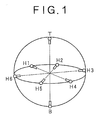
- FIG. 1 illustrates the principle of omnidirectional sound collection.
- omnidirectional sound collection sound is collected by a plurality of microphones arranged on an overall celestial sphere.
- six microphones H1 to H6 are disposed horizontally at equal distances (60 degrees) in a circumferential direction such that they are directed in radially outward directions, and microphones T and B are disposed vertically at the top and the bottom such that they are directed in upward and downward directions, respectively.
- the totaling eight microphones H1 to H6, T and B collect sound from all sound sources present in the overall celestial globe.
- the sound sources mentioned include sound sources in a sound recording studio, sound sources in an actual live place, sound sources of synthesized sound or virtual sound sources.
- FIG. 2 illustrates a configuration in principle of the surround sound field reproduction system according to the present invention.
- the surround sound field reproduction system includes six horizontal panners HP1 to HP6 for receiving output sound signals from the six microphones H1 to H6 for the horizontal direction to control horizontal localization, respectively.
- the horizontal panners HP1 to HP6 are connected such that they operate in an interlocking relationship with each other and outputs thereof are level-distributed to five mixing buses L, Cm, R, Rs and Ls.
- the mixing buses L, Cm, R, Rs and Ls are provided corresponding to surround reproduction output channels L, C, R, Ls and Rs (in the following description, corresponding mixing buses, surround reproduction output channels and sound signals may be denoted by like reference characters).
- the mixing bus L corresponds the output channel L for the forward left, the mixing bus Cm to the output channel C for the forward center, the mixing bus R to the output channel R for the forward left, the mixing bus Rs to the output channel Rs for the backward right, and the mixing bus Ls to the output channel Ls for the backward left. It is to be noted that, since, from the number of microphones, the present arrangement does not include a microphone which is directed to the forward center, the sound signal Cm for the forward center in the horizontal direction is mixed in the mixing bus Cm.
- the surround sound field reproduction system includes a vertical panner VP for receiving output sound signals of the microphone T for upper sound collection and the microphone B for lower sound collection of the vertical sound sources in omnidirectional sound collection and a signal of the mixing bus Cm to control the vertical localization.
- An output of the vertical panner VP forms an output channel C for the forward center.
- FIG. 3 illustrates a relationship between panning of sound sources in a horizontal direction and a reproduced sound field.
- FIG. 2 which illustrates a relationship between the inputted sound signals H1 to H6 and the sound signals L, Cm, R, Rs and Ls produced on the buses.
- the microphones H1 to H6 are directed in directions equally spaced from each other on a circumference to collect sound from all directions in the horizontal direction, the sound signals H1 to H6 are disposed in an equally spaced relationship from each other on the circumference of the circle shown in FIG. 3.
- a sound field necessary for surround sound reproduction has relative angles such that, where the upward direction in FIG. 3 is the direction of the front of the system, the sound signal L of the mixing bus L is directed in the leftward direction in FIG. 3; the sound signal Cm of the mixing bus Cm is directed in the forward center direction; the sound signal R of the mixing bus R is directed in the rightward direction; the sound signal Rs of the mixing bus Rs is directed the right backward direction; and the sound signal Ls of the mixing bus Ls is directed to the left backward direction.
- the relative angles mentioned are determined based on the arrangement of speakers and so forth so as to be optimum to the reproduction system and is not limited to the specific example shown in the drawings.
- FIG. 4 illustrates an attenuation characteristic of panning in the horizontal direction.
- the ratios at which the sound signals H1 to H6 are level-distributed to the mixing buses L, Cm, R, Rs and Ls are such as given below: L: 1 ⁇ H1 Cm: 0.708(H2 + H3) R: 1 ⁇ H4 Rs: 1 ⁇ H5 Ls: 1 ⁇ H6
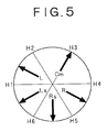
- FIG. 5 illustrates the sound sources in the horizontal direction and a reproduced sound field upon panning.
- the level distribution ratios of the sound signals H1 to H6 to the mixing buses L, Cm, R, Rs and Ls can be determined in the following manner from the attenuation characteristic described hereinabove with reference to FIG. 4: L: 0.708(H1 + H2) Cm: 1 ⁇ H3 R: 0.708(H4 + H5) Rs: 0.708(H5 + H6) Ls: 0.708(H6 + H1)
- FIG. 6 illustrates an attenuation characteristic of panning in the vertical direction
- FIG. 7 illustrates a relationship between panning of sound sources in the vertical direction and a reproduced sound field
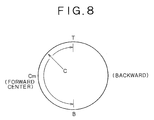
- FIG. 8 illustrates a relationship between sound sources in the vertical direction upon panning and a reproduced sound field.
- the mixing level to be supplied to the surround reproduction output channel from the two sound signals is given by C: 0.708(T + Cm) or 0.708(Cm + B)
- variable range in the vertical direction within which panning is permitted is 180 degrees in the front as seen in FIG. 7.
- the level distribution between the sound signals T and B in the vertical direction and the sound signal Cm mixed as a forwardly localized sound source in the horizontal direction is given, according to the attenuation characteristic described hereinabove with reference to FIG. 7, by C: 1 ⁇ Cm
- the omnidirectional sound collection uses unidirectional microphones to obtain presence and a directional characteristic so that a good degree of separation between channels can be obtained.
- the microphones to be used must have a sharper unidirectional characteristic.
- Sound signals of omnidirectionally collected sound can be recorded or distributed directly.
- the sound signals to be recorded or distributed may be in the form of original signals or otherwise in the form of compressed signals.
- a video recorder In order to record sound signals of omnidirectionally collected sound together with, for example, a video signal, a video recorder, a digital video tape recorder (VTR) or a like apparatus is used.
- VTR digital video tape recorder
- the apparatus mentioned since the apparatus mentioned have tracks for only two or four channels, the necessary sound channels are distributed to and recorded simultaneously into a plurality of video recorders or digital video tape recorders.
- the sound channels are recorded with the same time code, for example, the SMPTE (Society of Motion Picture and Television Engineers) time code into the video recorders or digital video tape recorders.
- SMPTE Society of Motion Picture and Television Engineers
- Another recording method may be employed wherein sound signals of omnidirectionally collected sound are recorded as they are using a multi-track recorder.
- the sound signals and the video signal are all recorded with the same time code.
- sound signals of omnidirectionally collected sound may be compressed into and digitally recorded in 2 channels.
- a recording medium in this instance preferably a digital VTR, a DAT (Digital Audio Tape) recorder, or a HDD (Hard Disk Drive) is used.
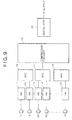
- FIG. 9 shows an example of a configuration of a recording system based on omnidirectional sound collection.
- the omnidirectionally collected sound recording system includes, at an inputting section thereof, head amplifiers 11, 12, 13, 14 and 15 for receiving sound signals collected by the microphones T and B for the vertical directions the microphones H1 to H6 for the horizontal direction.
- the head amplifiers 11, 12, 13, 14 and 15 have an AGC (Automatic Gain Control) function of amplifying a received sound signal with a predetermined amplification factor while adjusting the level of the sound signal suitably with respect to the compression level of a dynamic range.
- the AGC function can be enabled/disabled when necessary, and when it is enabled, the gains of the omnidirectional sound signals and the control amounts of the AGC are interlocked with each other among the head amplifiers 11, 12, 13, 14 and 15 for all channels.
- Outputs of the head amplifiers 11, 12, 13, 14 and 15 are connected to inputs of three analog to digital converters 16, 17 and 18 each for 2 channels.
- Each of the analog to digital converters 16, 17 and 18 converts analog signals of 2 channels into a serial digital signal of, for example, 16 to 24 bits.
- Outputs of the analog to digital converters 16, 17 and 18 are inputted to a compression encoder 19 which compresses digitally converted signals of 8 channels into signals of 2 channels.
- a compression encoder 19 which compresses digitally converted signals of 8 channels into signals of 2 channels.
- the "Dolby E” multi-channel coding technique developed by Dolby of the United States is employed.
- the sound compression technique "ATRAC (Adaptive TRansform Acoustic Coding)" developed by Sony of Japan may be used.
- An output of the compression encoder 19 is connected to a digital VTR 20 through an AES/EBU (Audio Engineering Society/European Broadcasting Union) twisted pair cable which is a digital audio interface for business use.
- AES/EBU Audio Engineering Society/European Broadcasting Union
- the collected sound signals of 8 channels are compressed into signals of 2 channels by the compression encoder 19.
- the serial digital signals of the 2 channels are recorded on two audio tracks of the digital VTR 20.
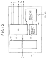
- FIG. 10 shows an example of a system configuration of the omnidirectional surround reproduction apparatus.
- the audio decoder board 30 includes a decoder 31 to which, for example, signals recorded on the digital VTR 20 shown in FIG. 9 or signals received on the real-time basis are inputted.
- the decoder 31 has a function of decoding 2-channel serial digital signals of the compression format inputted thereto into four 2-channel serial digital audio signals using a decoding technique of the "Dolby E" compression format. Outputs of the decoder 31 are connected to inputs of a DSP (Digital Signal Processor) 32.
- DSP Digital Signal Processor
- the DSP 32 has a function of processing four 2-channel serial digital audio signals to produce six surround reproduction output channels L, C, R, Ls, Rs and SW.
- the surround reproduction output channel SW here is an output channel for subwoofer which takes charge of reproduction of low-frequency components of all of the channels. Accordingly, the six surround reproduction output channels L, C, R, Ls, Rs and SW can be connected directly to an external 5.1 channel surround system.
- a pan/level control table 33 is connected to the DSP 32.
- the pan/level control table 33 stores mixing distribution data to the individual channels corresponding to panning operation amounts in the horizontal and vertical directions performed in accordance with an instruction of the listener, and passes, in response to coordinate data received from a direction inputting apparatus which is hereinafter described, corresponding pan position data for panning control to the DSP 32.
- the omnidirectional resolution need not be particularly high, and the panning can be controlled with a resolution of, for example, approximately 8 to 20 bits for the entire circumference in the horizontal direction and, for example, approximately 8 bits for the upward and downward range of 180 degrees in the vertical direction.
- the DSP 32 is further connected to an audio data/control PCI bridge 34 which performs conversion and transfer of a signal to and from a PCI (Peripheral Component Interconnect) bus of an extension slot of a personal computer.
- PCI Peripheral Component Interconnect
- serial digital signals compressed to 2 channels are decompressed and decoded by the decoder 31 so that the collected sound signals of the channels T, B and H1 to H6 are decoded into 2 channels ⁇ 4 serial digital audio signals.
- the four serial digital audio signals obtained by the decoding are mixed into the surround reproduction output channels L, C, R, Ls, Rs and SW for the individual directions by the DSP 32.
- a panning instruction is inputted from the direction inputting apparatus through the audio data/control PCI bridge 34, then a mixing control signal corresponding to the instruction is supplied from the pan/level control table 33 to the DSP 32, and the DSP 32 performs a mixing process in accordance with the instruction.
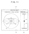
- FIG. 11 illustrates an example of a screen display of the direction inputting apparatus.
- the direction inputting apparatus 40 is used to output a panning instruction to the audio decoder board 30 of the omnidirectional surround reproduction apparatus and is displayed on a screen of a monitor of a personal computer.
- the screen of the direction inputting apparatus 40 includes a sub screen 41 for setting in a horizontal direction and another sub screen 42 for setting in a vertical direction.
- a full direction surround sound field is displayed on the sub screen 41 for horizontal setting through such a bird's-eye view that reproduction positions of the surround reproduction output channels L, C, R, Ls and Rs for the horizontal direction are viewed from an obliquely rearward upward position.
- an arrow mark 43 representative of a direction of a sound to be forwardly localized is disposed.
- the end of the arrow mark 43 is, for example, pointed with a mouse pointer and dragged in the leftward or rightward direction in the thus pointed state.
- the direction of the arrow mark 43 can be rotated by 360 degrees, and coordinate information in the horizontal direction inputted in this state is sent to the audio decoder board 30.
- the sub screen 42 for vertical setting includes an arrow mark 44 representative of the range of setting in the upward and downward direction and a mark 45 disposed on the line of the arrow mark 44 and representative of the localization in the upward and downward direction.
- the mark 45 is dragged in the upward or downward direction with the mouse pointer.
- the localization in the upward or downward direction can be inputted in this manner. Also the thus inputted coordinate information is sent to the audio decoder board 30 together with the horizontal input information.
- FIG. 12 illustrates a relationship between the horizontal direction inputs and the mixing buses.
- the horizontal panner has a resistance member 50 formed in a ring, and the mixing buses L, Cm, R, Rs and Ls are connected to positions on the circumference of the resistance member 50 in the corresponding horizontal directions.
- a rotor 51 is provided concentrically with the resistance member 50 such that it can rotate in response to a horizontal instruction input of the direction inputting apparatus 40, and movable pieces 52 to 57 are provided corresponding to the directions of the microphones H1 to H6 disposed horizontally on an outer periphery of the rotor 51 such that they contact with and slidably move on the resistance member 50. Sound signals obtained from the microphones H1 to H6 are inputted to the movable pieces 52 to 57, respectively.
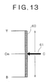
- FIG. 13 illustrates a relationship between the vertical direction input and the mixing buses.
- the vertical panner has a resistance member 60 formed in a straight line. Terminals to which sound signals from the microphones T and B disposed in the horizontal direction are connected to the opposite ends of the resistance member 60, and the mixing bus Cm is connected to a central position of the resistance member 60. Further, a movable piece 61 is provided which contacts with and slidably moves on the resistance member 60 linearly in accordance with a vertical instruction input from the direction inputting apparatus 40. The movable piece 61 is connected to the output channel C for the forward center.
- the foregoing description relates to a case wherein sound is collected in 6 channels in the horizontal direction. However, if it is intended to reproduce a sound field wherein a sound of an object of direction is discriminated more clearly, then the number of sound sources in the horizontal direction should be increased.
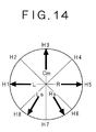
- a relationship between sound sources and a reproduced sound field where the number of sound sources in the horizontal direction is changed, for example, to 8 is described as an example.
- FIG. 14 illustrates a relationship between sound sources and a reproduced sound field where an increased number of sound sources for the horizontal direction are involved.
- the mixing buses L, Cm, R, Rs and Ls are the same as those described hereinabove where they are compatible with a 5.1 channel surround system.
- the sound sources are collected by eight microphones H1 to H8 directed in directions equally spaced from each other on a circumference to collect sound from all directions in the horizontal direction.
- the sound signals collected are level-distributed to the mixing buses L, Cm, R, Rs and Ls using coefficients determined based on attenuation characteristics between the channels.
- a surround sound field and a sound of an object of direction can be realized from at least three sound sources in the horizontal direction, and as the number of sound sources in the horizontal direction increases, a sound field wherein a sound of an object of direction is discriminated more clearly can be obtained.
- the surround sound field reproduction system is provided in a reproduction equipment side of the listener, and the listener decides a sound in which direction should be selected from among sound signals collected directly and supplied from omnidirectional sounds so that it may be the center of a surrounding sound field to be produced.
- the surround sound field reproduction system on the sound source side.
- omnidirectional sounds are distributed to a listener through an interactive broadcast (the Internet)
- the Internet it is possible to effect panning on the origination side in accordance with an instruction from the listener and distribute sound signals of the surround reproduction output channels L, C, R, Ls and Rs produced upon the panning as they are or after they are compressed and converted into sound signals of 2 channels so that the distributed signals may be received and reproduced as they are or after they are reproduced by the listener side.
- the listener can receive omnidirectionally collected sounds wherein a sound to which the listener is directed is forwardly localized and enjoy it in a desired surround sound field.
- the surround sound field is described above taking a 5.1 channel surround system as an example, it can be similarly applied also to a surround sound system which uses virtual 5.1 channels or 5 channels of the headphone type 5.1 channel surround system. Further, the surround sound field reproduction system according to the present invention becomes more effective if it is used together with a video signal.
Landscapes
- Physics & Mathematics (AREA)
- Engineering & Computer Science (AREA)
- Acoustics & Sound (AREA)
- Signal Processing (AREA)
- Stereophonic System (AREA)
Abstract
Description
Claims (18)
- A surround sound field reproduction system for forwardly localizing a sound to which a listener is directed from among omnidirectionally collected sounds, comprising:a plurality of horizontal panner means for individually receiving a plurality of sound signals of different input channels collected from sound sources distributed in a range of 360 degrees in a horizontal direction and distributing sound levels of the sound signals of the input channels in an interlocking relationship with each other to a plurality of output channels to control the horizontal localization; andvertical panner means for receiving a plurality of sound signals of different input channels collected from sound sources distributed in a range of 180 degrees in a vertical direction, changing a level distribution of the sound signals of the input channels to produce a sound signal and outputting the produced sound signal to an output channel for the front center to control the vertical localization.
- A surround sound field reproduction system according to claim 1, further comprising a number of mixing buses determined with reference to the number of output channels necessary for a reproduced sound field, outputs of said horizontal panner means being level-distributed to all of said mixing buses.
- A surround sound field reproduction system according to claim 2, wherein said mixing buses include five buses for the forward left, the forward center, the forward right, the backward left and the backward right to be mixed for horizontal localization.
- A surround sound field reproduction system according to claim 3, wherein said input channels include totaling eight channels including six channels for inputting sound signals of six directions collected from six directions of the forward left, the forward right, the left, the right, the backward left and the backward right in a horizontal direction and two channels for inputting upper and lower sound signals in a vertical direction, and said output channels include totaling five output channels including four output channels connected to the four mixing buses for the forward left, the forward right, the backward left and the backward right and one output channel connected to the mixing bus for the forward center for forward localization and an output of said vertical panner means to which the upper and lower input channels in the vertical direction are inputted.
- A surround sound field reproduction system according to claim 4, wherein said output channels further include a sixth output channel for outputting low-frequency components included in all of the output channels so as to be applied to a 5.1 channel surround system.
- A surround sound field reproduction system according to claim 1, further comprising direction inputting means for providing a panning operation instruction to said horizontal panner means and said vertical panner means so that the forward center may be localized to a direction in which the listener wants to listen to sound.
- A surround sound field reproduction system according to claim 6, wherein said direction inputting means issues the instruction through a network.
- A surround sound field reproduction system according to claim 1, wherein said input channels include six channels for inputting sound signals of six directions collected from six directions of the forward left, the forward right, the left, the right, the backward left and the backward right in the horizontal direction and two channels for inputting upper and lower sound signals in the vertical direction.
- A surround sound field reproduction system according to claim 8, wherein the sound signals in the horizontal direction and the sound signals in the vertical direction are inputted through a digital recording and/or reproduction apparatus or a network.
- A surround sound field reproduction method for forwardly localizing a sound to which a listener is directed from among omnidirectionally collected sounds, comprising the steps of:receiving a plurality of sound signals of different input channels collected from sound sources distributed in a range of 360 degrees in a horizontal direction and distributing sound levels of the sound signals of the input channels in an interlocking relationship with each other to a plurality of output channels to control the horizontal localization; andreceiving a plurality of sound signals of different input channels collected from sound sources distributed in a range of 180 degrees in a vertical direction, changing a level distribution of the sound signals of the input channels to produce a sound signal and outputting the produced sound signal to an output channel for the front center to control the vertical localization.
- A surround sound field reproduction method according to claim 10, further comprising a method of performing mixing of a number of sound signals determined with reference to the number of output channels necessary for a reproduced sound field, the sound signals of the input channels in the horizontal direction being level-distributed to all of the output channels.
- A surround sound field reproduction method according to claim 11, wherein the number of sound signals to be used for the mixing is five including sound signals for the forward left, the forward center, the forward right, the backward left and the backward right to be mixed for horizontal localization.
- A surround sound field reproduction method according to claim 12, wherein said input channels include totaling eight channels including six channels for inputting sound signals of six directions collected from six directions of the forward left, the forward right, the left, the right, the backward left and the backward right in a horizontal direction and two channels for inputting upper and lower sound signals in a vertical direction, and said output channels include totaling five output channels including four output channels for the forward left, the forward right, the backward left and the backward right and one output channel for a mixing signal between the signal for forward localization of the forward center and input signals from the upper and lower input channels in the vertical direction.
- A surround sound field reproduction method according to claim 13, further comprising a step of outputting low-frequency components included in all of the output channels through a sixth channel so as to be applied to a 5.1 channel surround system.
- A surround sound field reproduction method according to claim 10, further comprising a direction inputting step of providing a panning operation instruction so that the forward center may be localized to a direction in which the listener wants to listen to sound.
- A surround sound field reproduction method according to claim 15, wherein the panning operation instruction is issued through a network.
- A surround sound field reproduction method according to claim 10, wherein said input channels include six channels for inputting sound signals of six directions collected from six directions of the forward left, the forward right, the left, the right, the backward left and the backward right in the horizontal direction and two channels for inputting upper and lower sound signals in the vertical direction.
- A surround sound field reproduction method according to claim 17, wherein the sound signals in the horizontal direction and the sound signals in the vertical direction are inputted through a digital recording and/or reproduction apparatus or a network.
Applications Claiming Priority (2)
| Application Number | Priority Date | Filing Date | Title |
|---|---|---|---|
| JP2001144517A JP2002345097A (en) | 2001-05-15 | 2001-05-15 | Surround sound field playback system |
| JP2001144517 | 2001-05-15 |
Publications (2)
| Publication Number | Publication Date |
|---|---|
| EP1259097A2 true EP1259097A2 (en) | 2002-11-20 |
| EP1259097A3 EP1259097A3 (en) | 2006-03-01 |
Family
ID=18990454
Family Applications (1)
| Application Number | Title | Priority Date | Filing Date |
|---|---|---|---|
| EP02253378A Withdrawn EP1259097A3 (en) | 2001-05-15 | 2002-05-14 | Surround sound field reproduction system and surround sound field reproduction method |
Country Status (3)
| Country | Link |
|---|---|
| US (1) | US6934395B2 (en) |
| EP (1) | EP1259097A3 (en) |
| JP (1) | JP2002345097A (en) |
Cited By (1)
| Publication number | Priority date | Publication date | Assignee | Title |
|---|---|---|---|---|
| EP1534045A3 (en) * | 2003-11-21 | 2008-04-02 | Volkswagen AG | Adjustment device for an audio device in a vehicle and corresponding adjustment method |
Families Citing this family (21)
| Publication number | Priority date | Publication date | Assignee | Title |
|---|---|---|---|---|
| US8767969B1 (en) | 1999-09-27 | 2014-07-01 | Creative Technology Ltd | Process for removing voice from stereo recordings |
| US20030023429A1 (en) * | 2000-12-20 | 2003-01-30 | Octiv, Inc. | Digital signal processing techniques for improving audio clarity and intelligibility |
| FR2850183B1 (en) * | 2003-01-20 | 2005-06-24 | Remy Henri Denis Bruno | METHOD AND DEVICE FOR CONTROLLING A RESTITUTION ASSEMBLY FROM A MULTICHANNEL SIGNAL |
| US7558393B2 (en) * | 2003-03-18 | 2009-07-07 | Miller Iii Robert E | System and method for compatible 2D/3D (full sphere with height) surround sound reproduction |
| US7970144B1 (en) * | 2003-12-17 | 2011-06-28 | Creative Technology Ltd | Extracting and modifying a panned source for enhancement and upmix of audio signals |
| US7330552B1 (en) * | 2003-12-19 | 2008-02-12 | Lamance Andrew | Multiple positional channels from a conventional stereo signal pair |
| JP2005198251A (en) * | 2003-12-29 | 2005-07-21 | Korea Electronics Telecommun | Three-dimensional audio signal processing system and method using sphere |
| US7549123B1 (en) * | 2005-06-15 | 2009-06-16 | Apple Inc. | Mixing input channel signals to generate output channel signals |
| US8077888B2 (en) | 2005-12-29 | 2011-12-13 | Microsoft Corporation | Positioning audio output for users surrounding an interactive display surface |
| JP4949706B2 (en) * | 2006-03-17 | 2012-06-13 | 公立大学法人会津大学 | Sound image localization apparatus and sound image localization method |
| JP4689506B2 (en) * | 2006-03-17 | 2011-05-25 | 公立大学法人会津大学 | Sound image localization apparatus and sound image localization method |
| JP4914124B2 (en) * | 2006-06-14 | 2012-04-11 | パナソニック株式会社 | Sound image control apparatus and sound image control method |
| KR100829560B1 (en) * | 2006-08-09 | 2008-05-14 | 삼성전자주식회사 | Method and apparatus for encoding / decoding multi-channel audio signal, Decoding method and apparatus for outputting multi-channel downmixed signal in 2 channels |
| JP5310506B2 (en) | 2009-03-26 | 2013-10-09 | ヤマハ株式会社 | Audio mixer |
| US9264813B2 (en) * | 2010-03-04 | 2016-02-16 | Logitech, Europe S.A. | Virtual surround for loudspeakers with increased constant directivity |
| US8542854B2 (en) * | 2010-03-04 | 2013-09-24 | Logitech Europe, S.A. | Virtual surround for loudspeakers with increased constant directivity |
| JP5602688B2 (en) * | 2011-07-04 | 2014-10-08 | 日本電信電話株式会社 | Sound image localization control system, communication server, multipoint connection device, and sound image localization control method |
| KR102149046B1 (en) * | 2013-07-05 | 2020-08-28 | 한국전자통신연구원 | Virtual sound image localization in two and three dimensional space |
| JP6412931B2 (en) * | 2013-10-07 | 2018-10-24 | ドルビー ラボラトリーズ ライセンシング コーポレイション | Spatial audio system and method |
| TWI736542B (en) | 2015-08-06 | 2021-08-21 | 日商新力股份有限公司 | Information processing device, data distribution server, information processing method, and non-temporary computer-readable recording medium |
| US10861467B2 (en) * | 2017-03-01 | 2020-12-08 | Dolby Laboratories Licensing Corporation | Audio processing in adaptive intermediate spatial format |
Family Cites Families (8)
| Publication number | Priority date | Publication date | Assignee | Title |
|---|---|---|---|---|
| US5440639A (en) * | 1992-10-14 | 1995-08-08 | Yamaha Corporation | Sound localization control apparatus |
| US5943427A (en) * | 1995-04-21 | 1999-08-24 | Creative Technology Ltd. | Method and apparatus for three dimensional audio spatialization |
| FR2738099B1 (en) * | 1995-08-25 | 1997-10-24 | France Telecom | METHOD FOR SIMULATING THE ACOUSTIC QUALITY OF A ROOM AND ASSOCIATED AUDIO-DIGITAL PROCESSOR |
| US5857026A (en) * | 1996-03-26 | 1999-01-05 | Scheiber; Peter | Space-mapping sound system |
| US6072878A (en) * | 1997-09-24 | 2000-06-06 | Sonic Solutions | Multi-channel surround sound mastering and reproduction techniques that preserve spatial harmonics |
| US6665407B1 (en) * | 1998-09-28 | 2003-12-16 | Creative Technology Ltd. | Three channel panning system |
| US6507658B1 (en) * | 1999-01-27 | 2003-01-14 | Kind Of Loud Technologies, Llc | Surround sound panner |
| US6694027B1 (en) * | 1999-03-09 | 2004-02-17 | Smart Devices, Inc. | Discrete multi-channel/5-2-5 matrix system |
-
2001
- 2001-05-15 JP JP2001144517A patent/JP2002345097A/en active Pending
-
2002
- 2002-05-13 US US10/145,162 patent/US6934395B2/en not_active Expired - Fee Related
- 2002-05-14 EP EP02253378A patent/EP1259097A3/en not_active Withdrawn
Cited By (1)
| Publication number | Priority date | Publication date | Assignee | Title |
|---|---|---|---|---|
| EP1534045A3 (en) * | 2003-11-21 | 2008-04-02 | Volkswagen AG | Adjustment device for an audio device in a vehicle and corresponding adjustment method |
Also Published As
| Publication number | Publication date |
|---|---|
| EP1259097A3 (en) | 2006-03-01 |
| US20020172370A1 (en) | 2002-11-21 |
| US6934395B2 (en) | 2005-08-23 |
| JP2002345097A (en) | 2002-11-29 |
Similar Documents
| Publication | Publication Date | Title |
|---|---|---|
| US6934395B2 (en) | Surround sound field reproduction system and surround sound field reproduction method | |
| US5546465A (en) | Audio playback apparatus and method | |
| JP3885976B2 (en) | Computer, computer system and desktop theater system | |
| TW396713B (en) | Multi-channel audio enhancement system for use in recording and playback and methods for providing same | |
| KR100788038B1 (en) | Multichannel acoustic signal reproducing apparatus | |
| US20120014524A1 (en) | Distributed bass | |
| JP2011515942A (en) | Object-oriented 3D audio display device | |
| CA2399495A1 (en) | Use of voice-to-remaining audio (vra) in consumer applications | |
| AU2001231228A1 (en) | Use of voice-to-remaining audio (VRA) in consumer applications | |
| US11310616B2 (en) | Method for outputting audio signal using scene orientation information in an audio decoder, and apparatus for outputting audio signal using the same | |
| JP2015126460A (en) | Source equipment | |
| JPH10336798A (en) | Sound field correction circuit | |
| CN111492674A (en) | Processing mono signals in a 3D audio decoder to deliver binaural content | |
| JP2002223493A (en) | Multi-channel sound pickup device | |
| JPH0819089A (en) | Speaker system for sound field reproduction | |
| US7408851B2 (en) | Pseudo multi-channel play-back apparatus | |
| US20050047619A1 (en) | Apparatus, method, and program for creating all-around acoustic field | |
| CN114915874A (en) | Audio processing method, apparatus, device, medium, and program product | |
| JP3740780B2 (en) | Multi-channel playback device | |
| KR101417065B1 (en) | Apparatus and method for implementing a virtual stereo sound | |
| JP2004513583A (en) | Portable multi-channel amplifier | |
| JP4538860B2 (en) | Audio band signal recording / reproducing apparatus, audio band signal recording / reproducing method, audio band signal recording apparatus, and audio band signal recording method | |
| US20040096073A1 (en) | Portable multi-channel amplifier | |
| US20060062396A1 (en) | Optical reproducing apparatus and method to transform external audio into multi-channel surround sound | |
| JP2002152897A (en) | Audio signal processing method and audio signal processing device |
Legal Events
| Date | Code | Title | Description |
|---|---|---|---|
| PUAI | Public reference made under article 153(3) epc to a published international application that has entered the european phase |
Free format text: ORIGINAL CODE: 0009012 |
|
| AK | Designated contracting states |
Kind code of ref document: A2 Designated state(s): AT BE CH CY DE DK ES FI FR GB GR IE IT LI LU MC NL PT SE TR |
|
| AX | Request for extension of the european patent |
Free format text: AL;LT;LV;MK;RO;SI |
|
| PUAL | Search report despatched |
Free format text: ORIGINAL CODE: 0009013 |
|
| AK | Designated contracting states |
Kind code of ref document: A3 Designated state(s): AT BE CH CY DE DK ES FI FR GB GR IE IT LI LU MC NL PT SE TR |
|
| AX | Request for extension of the european patent |
Extension state: AL LT LV MK RO SI |
|
| 17P | Request for examination filed |
Effective date: 20060816 |
|
| 17Q | First examination report despatched |
Effective date: 20061004 |
|
| AKX | Designation fees paid |
Designated state(s): DE FR GB |
|
| GRAP | Despatch of communication of intention to grant a patent |
Free format text: ORIGINAL CODE: EPIDOSNIGR1 |
|
| STAA | Information on the status of an ep patent application or granted ep patent |
Free format text: STATUS: THE APPLICATION IS DEEMED TO BE WITHDRAWN |
|
| 18D | Application deemed to be withdrawn |
Effective date: 20071010 |