EP1259047A2 - Portable electronic device multipart housing electrical connection - Google Patents
Portable electronic device multipart housing electrical connection Download PDFInfo
- Publication number
- EP1259047A2 EP1259047A2 EP02252940A EP02252940A EP1259047A2 EP 1259047 A2 EP1259047 A2 EP 1259047A2 EP 02252940 A EP02252940 A EP 02252940A EP 02252940 A EP02252940 A EP 02252940A EP 1259047 A2 EP1259047 A2 EP 1259047A2
- Authority
- EP
- European Patent Office
- Prior art keywords
- housing
- contact
- components
- supported
- portable device
- Prior art date
- Legal status (The legal status is an assumption and is not a legal conclusion. Google has not performed a legal analysis and makes no representation as to the accuracy of the status listed.)
- Granted
Links
Images


Classifications
-
- H—ELECTRICITY
- H04—ELECTRIC COMMUNICATION TECHNIQUE
- H04M—TELEPHONIC COMMUNICATION
- H04M1/00—Substation equipment, e.g. for use by subscribers
- H04M1/02—Constructional features of telephone sets
- H04M1/0202—Portable telephone sets, e.g. cordless phones, mobile phones or bar type handsets
- H04M1/0206—Portable telephones comprising a plurality of mechanically joined movable body parts, e.g. hinged housings
- H04M1/0208—Portable telephones comprising a plurality of mechanically joined movable body parts, e.g. hinged housings characterized by the relative motions of the body parts
- H04M1/0235—Slidable or telescopic telephones, i.e. with a relative translation movement of the body parts; Telephones using a combination of translation and other relative motions of the body parts
- H04M1/0237—Sliding mechanism with one degree of freedom
-
- H—ELECTRICITY
- H01—ELECTRIC ELEMENTS
- H01R—ELECTRICALLY-CONDUCTIVE CONNECTIONS; STRUCTURAL ASSOCIATIONS OF A PLURALITY OF MUTUALLY-INSULATED ELECTRICAL CONNECTING ELEMENTS; COUPLING DEVICES; CURRENT COLLECTORS
- H01R35/00—Flexible or turnable line connectors, i.e. the rotation angle being limited
- H01R35/04—Turnable line connectors with limited rotation angle with frictional contact members
-
- H—ELECTRICITY
- H04—ELECTRIC COMMUNICATION TECHNIQUE
- H04M—TELEPHONIC COMMUNICATION
- H04M1/00—Substation equipment, e.g. for use by subscribers
- H04M1/02—Constructional features of telephone sets
- H04M1/0202—Portable telephone sets, e.g. cordless phones, mobile phones or bar type handsets
- H04M1/0206—Portable telephones comprising a plurality of mechanically joined movable body parts, e.g. hinged housings
- H04M1/0208—Portable telephones comprising a plurality of mechanically joined movable body parts, e.g. hinged housings characterized by the relative motions of the body parts
- H04M1/0214—Foldable telephones, i.e. with body parts pivoting to an open position around an axis parallel to the plane they define in closed position
Definitions
- This invention relates to the electrical connection between a main body and the flipping or folding part of a portable communication device.
- Mobile phones often employ a multipart housing, which folds or uses a flip. Electrical or electronic components are generally located in each part of the housing.
- the transceiver housing and the folding or flipping part are conventionally electrically connected to each other with a flex or other type of cable which needs to be threaded through the hinge connecting the respective parts.
- At least one first contact is supported at a first portion of the housing and is connected to at least one electrical component in the housing.
- At least one second contact is supported at a second portion of the housing and is connected to at least one electrical component in the housing.
- At least one third contact is supported by the part and is connected to at least one electrical component in the part. The at least one third contact is arranged to engage the at least one first contact when the part is in the first position and to engage the at least one second contact when the part is in the second position.
- the portable electronic device is a portable communication device such as, for example, a mobile or radio telephone.
- a process for operating a portable communication device comprises providing a device housing and a part arranged to overlie at least a portion of the housing in a first position.
- the part is pivoted away from the housing to a second position.
- An electrical connection is provided between at least one electrical component in the part and at least one electrical component in the housing when the part is at the first or second positions. The electrical connection is broken during the pivoting movement of the part.
- This invention is aimed at reducing cost by eliminating the use of a cable running through the hinge. It is also aimed improving the reliability of the electrical connection between the housing and the part in their operative positions.
- This invention is applicable to a wide range of electronic devices which employ multipart housings which fold about a hinge, as for example, notebook computers, hand held computers, PDAs, folding keyboards, or any other electronic device which includes a hinge between folding housing parts and requires electrical signal communication between the parts. Most preferably it is used with portable communication devices such as mobile or radio telephones, which fold or use a flip.
- a radio telephone 10 is comprised of a device housing 12 and a cover or flipping part 14 arranged to overlie at least a portion of the housing 12 in a first position as shown and arranged for pivoting movement away from the housing 12 to a second position as shown in Fig. 7.
- the housing 12 in this embodiment may support telephone one or more of the following: telephone circuitry, a display, a microphone, a battery, an antenna, keys, or various combinations of these elements.
- the cover part 14 in this embodiment may support one or more of the following; a speaker, a display, keys, a battery, telephone circuitry, an antenna, or various combinations of these elements.
- a hinge 16 connects the housing 12 and the cover part 14 for providing the relative pivoting movement between the housing 12 and the part 14.
- an electrical connector 18 is used to provide for electrically connection between electrical components (not shown) in the cover part 14 and electrical components (not shown) in the housing 12.
- the electrical connector 18 of this invention eliminates the need for a flex or cable to be threaded through the hinge 16 between the housing 12 and part 14. It is a unique aspect of this invention that the electrical connector 18, provides the electrical connection substantially only at the first and second positions of the part 14 and breaks the electrical connection during the pivoting movement of the part. This breaking of the circuit permits the connections at the first and second positions to be used in the control scheme of the radio telephone 10 as desired.
- the electrical connector 18 preferably comprises at least one first contact 20 supported at a first portion 22 of the housing 12 which is connected to at least one of the electrical components in the housing 12.
- at least one second contact 24 is supported at a second portion 26 of the housing 12 and is connected to at least one of the electrical components (not shown) in the housing 12.
- At least one third contact 28 is supported by the cover part 14 and is connected to at least one of the electronic components in the cover part.
- the at least one third contact 28 engages a one of the at least one first contacts 20 when the cover part 14 is in the first position as in Fig. 1 and engages one of the at least one second contacts 24 when the cover part 14 is in the second position as in Fig. 7.
- the first 20 and second 24 contacts comprise pads and the third contacts 28 comprise projections.
- the hinge 16 is also arranged to provide for linear movement of the cover part 14 relative to the device housing 12.
- the linear movement is provided as in Fig. 8 by a second pin 40 supported in each arm 32.
- At least one spring 42 is provided for biasing the cover part 14 toward the device housing 12 at the first and second positions to provide proper contact force in the engagement between the at least one first 20 or second 24 contacts with the at least one third contact 28, at the respective first and second positions.
- the spring 42 in Fig. 8 is a tension spring supported about pin 36 at one of its ends and about pin 40 at the opposing end. Linear movement occurs when the arm 32 moves linearly relative to pin 36 which rides in the channel of the arm.
- At least one detent 50 is provided between the housing 12 and the part 14 at the first position. and at least one second detent 50 is provided between the housing 12 and the part 14 at the second position.
- the cover part 14 moves linearly in addition to pivoting as the detents 50 are engaged.
- the detents 50 comprise at least one rail 52 supported at each of the first 22 and second 26 portions of the housing 12 and at least one projection 54 supported by the cover part 14 for engaging a respective one of the rails 52.
- a process for operating a portable electronic device 10 which comprises: providing a device housing 12 and a cover part 14 arranged to overlie at least a portion of the housing 12 in a first position.
- the part 14 is pivoted away from the housing 12 to a second position.
- An electrical connection is provided between at least one electrical component in the part 12 and at least one electrical component in the housing 12 when the part 14 is at the first or second positions. The electrical connection is broken during the pivoting movement of the part 14.
- At least one first contact 20 is provided which is supported at a first portion 22 of the housing 12 and connected to at least one of the electrical components in the housing 12.
- At least one second contact is provided which is supported at a second portion 26 of the housing 12 and connected to at least one of the electrical components in the housing.
- At least one third contact 28 is supported by the part 14 and connected to at least one of the electrical components in the part 14. In this preferred process the at least one third contact 28 engages with the at least one first contact 20 when the part is in the first position and the at least one third contact 28 engages the at least one second contact when the part is in the second position. The respective engagements occur upon moving the cover part 14 to the first position or the second position.
- the part 14 is moved relative to the housing 12 as well as pivotally and is biased toward the housing 12 at the first and second positions, to provide the engagement between the at least one first 20 or second 24 contacts with the at least one third contact 28, at the respective first and second positions.
- the process includes providing a first detent 50 between the housing 12 and the part 14 at the first position and a second detent 50 between the housing 12 and the part 14 at the second position and moving the part 14 linearly in addition to pivoting when engaging the detents.
- Fig. 3 the cover part 14 is shown in the first position as in Fig. 1.
- the spring force or biasing direction is shown by arrow 60.
- Fig. 4 as the cover part 14 is moved in the direction of arrow 62 away from the device housing 12 the contacts 20 and 28 are opened and the cover part 14 moves linearly in the direction of arrow 64 in order to disengage form the detent 50 at the first position.
- Figs. 5-7 as the cover part 14 pivots to the second position it moves linearly in the direction of arrow 66 as projection 54 moves along the ramp portion 56 of rail 52. The cover part 14 then moves in the direction of arrow 68 of Fig.
- the hinge 100 comprises a frame 102 which is secured internally of the device housing 12 to a side wall 104 thereof, by any desired means. For example by the use of fasteners or adhesive or the frame can be molded as part of the wall 104.
- the frame 102 has a "U" shape comprising a bottom wall 106 joining opposing "L" shaped legs or sides 108 and 110.
- a hinge plate 112 is arranged to slide within the frame 102.
- a convex curved compression spring 114 is mounted in slots 116 to each of the opposing sides 118 and 120 of the plate 112.
- a pivot pin 122 is pivotally supported at one end within a bushing 124 mounted to a central portion of the hinge plate 112. The other end of the pin 122 is fixedly mounted to the arm support member 126 toward one end of the support member 126.
- the support member 126 is nested within the channel of the cover part 14 arms.
- the channel shaped arm 32 of the cover part is secured to the support member 126 by a fastener or any other desired means. For example, a screw can pass through the arm 32 and be threaded into hole 128 in the support member.
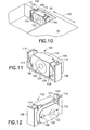
- the hinge 100 permits the cover part 14 to rotate about the pivot axis of the pin 122 and to move in either direction as shown by the arrow 130.
- this type of compression spring hinge 100 the cover part 14 is able to move in the same manner as discussed with respect to the previous embodiments to ensure adequate contact force between the contacts 20 or 24 and the contacts 28.
- the use of the two compression springs 114 insures that the cover part can properly navigate the detents 50 when the part is moved to either the first or the second positions.
Landscapes
- Engineering & Computer Science (AREA)
- Signal Processing (AREA)
- Telephone Set Structure (AREA)
- Connector Housings Or Holding Contact Members (AREA)
Abstract
Description
Claims (19)
- A portable electronic device comprising:a device housing (12);a part (14) arranged to overlie at least a portion of said housing in a first position and arranged for pivoting movement away from said housing to a second position;a hinge (16) connecting said housing and said part for providing said pivoting movement of said part;an electrical connector (18) for providing electrically connection between components in said part and components in said housing, characterized by said electrical connector providing said electrical connection at said first andsecond positions of said part, but breaking the electrical connection during the pivoting movement of said part.
- The portable device of claim 1 wherein said electrical connector comprises:at least one first contact supported at a first portion of said housing and connected to at least one of said components in said housing,at least one second contact supported at a second portion of said housing and connected to at least one of said components in said housing, andat least one third contact supported by said part and connected to at least one of said components in said part, said at least one third contact engaging said at least one first contact when said part is in said first position andengaging said at least one second contact when said part is in said second position.
- The portable device of claim 1 or 2 wherein said hinge is arranged to provide for linear movement of said part relative to said housing as well as for said pivoting movement and further including at least one spring for biasing said part toward said housing at said first and second positions to provide engagement of the at least one first or second contacts with said at least one third contact, at the respective first and second positions.
- The portable device of claim 3 wherein a first detent is provided between said housing and said part at said first position and a second detent is provided between said housing and said part at said second position and wherein said part moves linearly in addition to pivoting when engaging said detents.
- The portable device of claim 4 wherein said hinge comprises a first hinge element at one side of said housing and a second hinge element at an opposing side of said housing, and wherein said part includes two opposing arms extending from one side and an opposing side of said part and wherein free ends of said arms are supported for said pivotal and linear movement by said respective first and second hinge elements.
- The portable device of claim 5 wherein said spring comprises at least one tension spring connected between each of said respective hinge elements and a respective one of said arms.
- The portable device of claim 5 wherein said spring comprises at least one compression spring arranged to engage each of said hinge elements.
- The portable device of claim 3 wherein said first and second contacts comprise pads and said third contacts comprise projections.
- The portable device of claim 4 wherein said detents comprise at least one rail supported at each of said first and second portions of said housing and at least one projection supported by said part for engaging a respective one of said rails to move said part in a first linear fashion when said projection engages said rail and in an opposing linear direction when said projection disengages from the respective one of said rails.
- The portable device of any preceding claim and comprising a radio telephone.
- The portable device of claim 10 wherein said radio telephone comprises a folding telephone wherein said housing comprises a first operative portion of said telephone and said part comprises a second operative portion of said telephone.
- The portable device of claim 10 wherein said radio telephone comprises a flip phone wherein said housing comprises the principal operative portion of said telephone and said part comprises a flip cover of said telephone.
- The portable device of any preceding claim wherein said components comprise electrical or electronic devices.
- The portable device of any of claims 1 to 9 which comprises a portable communication device.
- A portable communication device comprising:a device housing;a part arranged to overlie at least a portion of said housing in a first position and arranged for pivoting movement away from said housing to a second position;a hinge connecting said housing and said part for providing said pivoting movement of said part;an electrical connector for providing electrically connection between at least one electrical component in said part and at least one electrical component in said housing, said electrical connector providing said electrical connection at said first and second positions of said part, but breaking the electrical connection during the pivoting movement of said part, said electrical connector comprising:at least one first contact supported at a first portion of said housing and connected to at least one of said components in said housing,at least one second contact supported at a second portion of said housing and connected to at least one of said components in said housing, andat least one third contact supported by said part and connected to at least one of said components in said part, said at least one third contact engaging said at least one first contact when said part is in said first position andengaging said at least one second contact when said part is in said second position.
- A process for operating a portable electronic device that comprises a device housing, a part arranged to overlie at least a portion of said housing in a first position, with components in said part and components in said housing, the process comprising:pivoting said part away from said housing to a second position;providing electrically connection between said components in said part andsaid components in said housing when said part is at said first or second positions; andbreaking the electrical connection during the pivoting movement of said part.
- The process for operating a portable electronic device as in claim 16 wherein said electrical connector comprises:at least one first contact supported at a first portion of said housing and connected to at least one of said components in said housing,at least one second contact supported at a second portion of said housing and connected to at least one of said components in said housing, andat least one third contact supported by said part and connected to at least one of said components in said part; the process includingengaging said at least one third contact with said at least one first contact when said part is in said first position and engaging said at least one secondcontact when said part is in said second position.
- The process for operating a portable electronic device as in claim 17 which comprises moving said part linearly relative to said housing as well as pivotally and biasing said part toward said housing at said first and second positions to engage the at least one first or second contacts with the at least one third contact, at the respective first and second positions.
- The process for operating a portable electronic device as in claim 18 further comprising providing a first detent between said housing and said part at said first position and a second detent between said housing and said part at said second position and moving said part linearly in addition to pivoting when engaging said detents.
Applications Claiming Priority (2)
| Application Number | Priority Date | Filing Date | Title |
|---|---|---|---|
| US09/860,787 US6842627B2 (en) | 2001-05-18 | 2001-05-18 | Portable electronic device multipart housing electrical connection |
| US860787 | 2001-05-18 |
Publications (3)
| Publication Number | Publication Date |
|---|---|
| EP1259047A2 true EP1259047A2 (en) | 2002-11-20 |
| EP1259047A3 EP1259047A3 (en) | 2004-02-04 |
| EP1259047B1 EP1259047B1 (en) | 2006-03-29 |
Family
ID=25334008
Family Applications (1)
| Application Number | Title | Priority Date | Filing Date |
|---|---|---|---|
| EP02252940A Expired - Lifetime EP1259047B1 (en) | 2001-05-18 | 2002-04-25 | Portable electronic device multipart housing electrical connection |
Country Status (3)
| Country | Link |
|---|---|
| US (1) | US6842627B2 (en) |
| EP (1) | EP1259047B1 (en) |
| DE (1) | DE60210219T2 (en) |
Cited By (2)
| Publication number | Priority date | Publication date | Assignee | Title |
|---|---|---|---|---|
| EP1439685A1 (en) * | 2003-01-17 | 2004-07-21 | Motorola, Inc. | Flip-phone cover |
| WO2008000288A1 (en) * | 2006-06-28 | 2008-01-03 | Nokia Corporation | Slide-tilt mechanism for an electronic device |
Families Citing this family (12)
| Publication number | Priority date | Publication date | Assignee | Title |
|---|---|---|---|---|
| KR100474678B1 (en) * | 2002-10-24 | 2005-03-10 | 삼성전자주식회사 | Portable communication apparatus with data inputting expansion |
| JP4125653B2 (en) | 2002-10-30 | 2008-07-30 | 日本電気株式会社 | Portable information terminal device |
| TWM257602U (en) * | 2004-04-27 | 2005-02-21 | Hon Hai Prec Ind Co Ltd | Hinge structure |
| US20070013608A1 (en) * | 2005-07-12 | 2007-01-18 | Goo Siew C | Dual display electronic device |
| US20070127199A1 (en) * | 2005-12-06 | 2007-06-07 | Arneson Theodore R | Electronic device hinge mechanism |
| US7331552B2 (en) * | 2006-01-17 | 2008-02-19 | Infocus Corporation | Hollow pivot |
| US7725988B2 (en) * | 2006-02-15 | 2010-06-01 | Lg Electronics Inc. | Hinge assembly and mobile device having the same |
| US7690576B2 (en) * | 2006-07-19 | 2010-04-06 | Research In Motion Limited | Handheld mobile communication device with moveable display/cover member |
| CN102726033A (en) * | 2010-01-28 | 2012-10-10 | 日本电气株式会社 | Portable electronic apparatus |
| US8606340B2 (en) | 2010-11-22 | 2013-12-10 | Blackberry Limited | Multi-display mobile device |
| US9155213B2 (en) | 2013-08-02 | 2015-10-06 | Craig Jones | Affixable belt clip for a phone incorporating an adjustable kickstand |
| US11146302B2 (en) * | 2017-10-04 | 2021-10-12 | Alfred Marcum | Mobile phone protective “battery cases” that provide housing and universal hookup for “proximate hardware” comprised of affixed deployable, and/or removable structures that analogously execute “multiple differing phone applications” |
Family Cites Families (8)
| Publication number | Priority date | Publication date | Assignee | Title |
|---|---|---|---|---|
| US5267868A (en) * | 1992-10-01 | 1993-12-07 | Molex Incorporated | Shielded electrical connector assemblies |
| EP0836308A1 (en) | 1996-10-09 | 1998-04-15 | Framatome Connectors International | Portable telephone with rotary contacts |
| WO1998019434A1 (en) | 1996-10-29 | 1998-05-07 | Ericsson Inc. | Telecommunication apparatus having dual keypads |
| KR100228315B1 (en) * | 1997-03-04 | 1999-11-01 | 윤종용 | Flip type microphone device |
| US5956398A (en) * | 1997-07-11 | 1999-09-21 | Ericsson Inc. | Telephone switching mechanism |
| SE515153C2 (en) * | 1998-12-01 | 2001-06-18 | Ericsson Mobile Comm Ab | Device on a mobile phone |
| WO2000069149A1 (en) * | 1999-05-06 | 2000-11-16 | Qualcomm Incorporated | Detection of flip closure state of a flip phone |
| BR0010237A (en) | 1999-05-06 | 2003-07-01 | Qualcomm Inc | Selecting the Flip Phone Operation Mode by Using the Flip Position |
-
2001
- 2001-05-18 US US09/860,787 patent/US6842627B2/en not_active Expired - Lifetime
-
2002
- 2002-04-25 DE DE60210219T patent/DE60210219T2/en not_active Expired - Lifetime
- 2002-04-25 EP EP02252940A patent/EP1259047B1/en not_active Expired - Lifetime
Cited By (3)
| Publication number | Priority date | Publication date | Assignee | Title |
|---|---|---|---|---|
| EP1439685A1 (en) * | 2003-01-17 | 2004-07-21 | Motorola, Inc. | Flip-phone cover |
| WO2004066597A1 (en) * | 2003-01-17 | 2004-08-05 | Motorola Inc | Flip-phone cover |
| WO2008000288A1 (en) * | 2006-06-28 | 2008-01-03 | Nokia Corporation | Slide-tilt mechanism for an electronic device |
Also Published As
| Publication number | Publication date |
|---|---|
| EP1259047B1 (en) | 2006-03-29 |
| EP1259047A3 (en) | 2004-02-04 |
| US20020173334A1 (en) | 2002-11-21 |
| US6842627B2 (en) | 2005-01-11 |
| DE60210219T2 (en) | 2007-03-29 |
| DE60210219D1 (en) | 2006-05-18 |
Similar Documents
| Publication | Publication Date | Title |
|---|---|---|
| US6842627B2 (en) | Portable electronic device multipart housing electrical connection | |
| US6484016B1 (en) | Device for connecting a main board with an LCD Module in a folder type portable radiotelephone | |
| JP4746668B2 (en) | Telescopic phone | |
| US7832058B2 (en) | Swivel hinge assembly for foldable electronic device | |
| JP3959086B2 (en) | Slider assembly for mobile communication terminals | |
| US8320980B2 (en) | Antenna assembly of mobile terminal | |
| US20080005867A1 (en) | Sliding mechanism for slide-type portable electronic device | |
| EP1439685B1 (en) | Flip-phone cover | |
| US7401383B2 (en) | Hinge connector for folding-type electronic apparatus | |
| KR100770855B1 (en) | Spring and semi-automatic sliding device using same and sliding type portable communication terminal using same | |
| US8299376B2 (en) | Key button mechanism and electronic device using the same | |
| US8453299B2 (en) | Connecting module and sliding mechanism for electronic device | |
| KR20050120383A (en) | Circuit connecting apparatus for portable terminal | |
| US20070127199A1 (en) | Electronic device hinge mechanism | |
| US7486974B2 (en) | Hinged device | |
| US7832055B2 (en) | Hinge | |
| JP2006128808A (en) | Sliding mobile phone | |
| US8379396B2 (en) | Electronic device and connecting mechanism thereof | |
| CN114893494A (en) | Damping mechanism and terminal | |
| WO2003075545A1 (en) | Foldable-type portable communicator | |
| CN117714566B (en) | Hinge assembly and electronic device | |
| US20090109614A1 (en) | Portable terminal having long stroke hinge | |
| TWI353093B (en) | Signal switch module | |
| KR20000031077A (en) | Automatic switching device mounted in hinge of flip type mobile phone | |
| KR100904074B1 (en) | Sliding Hinge Device for Mobile Device |
Legal Events
| Date | Code | Title | Description |
|---|---|---|---|
| PUAI | Public reference made under article 153(3) epc to a published international application that has entered the european phase |
Free format text: ORIGINAL CODE: 0009012 |
|
| AK | Designated contracting states |
Kind code of ref document: A2 Designated state(s): AT BE CH CY DE DK ES FI FR GB GR IE IT LI LU MC NL PT SE TR |
|
| AX | Request for extension of the european patent |
Free format text: AL;LT;LV;MK;RO;SI |
|
| PUAL | Search report despatched |
Free format text: ORIGINAL CODE: 0009013 |
|
| AK | Designated contracting states |
Kind code of ref document: A3 Designated state(s): AT BE CH CY DE DK ES FI FR GB GR IE IT LI LU MC NL PT SE TR |
|
| AX | Request for extension of the european patent |
Extension state: AL LT LV MK RO SI |
|
| 17P | Request for examination filed |
Effective date: 20040617 |
|
| 17Q | First examination report despatched |
Effective date: 20040720 |
|
| AKX | Designation fees paid |
Designated state(s): DE FI FR GB NL |
|
| GRAP | Despatch of communication of intention to grant a patent |
Free format text: ORIGINAL CODE: EPIDOSNIGR1 |
|
| RIN1 | Information on inventor provided before grant (corrected) |
Inventor name: HALKOLA, ONNI-MATTI Inventor name: HARSU, HEIKKI Inventor name: AALTONEN, ANTERO Inventor name: LAU, KING Inventor name: EKQVIST, PEKKA |
|
| GRAS | Grant fee paid |
Free format text: ORIGINAL CODE: EPIDOSNIGR3 |
|
| GRAA | (expected) grant |
Free format text: ORIGINAL CODE: 0009210 |
|
| AK | Designated contracting states |
Kind code of ref document: B1 Designated state(s): DE FI FR GB NL |
|
| REG | Reference to a national code |
Ref country code: GB Ref legal event code: FG4D |
|
| REF | Corresponds to: |
Ref document number: 60210219 Country of ref document: DE Date of ref document: 20060518 Kind code of ref document: P |
|
| ET | Fr: translation filed | ||
| PLBE | No opposition filed within time limit |
Free format text: ORIGINAL CODE: 0009261 |
|
| STAA | Information on the status of an ep patent application or granted ep patent |
Free format text: STATUS: NO OPPOSITION FILED WITHIN TIME LIMIT |
|
| 26N | No opposition filed |
Effective date: 20070102 |
|
| PGFP | Annual fee paid to national office [announced via postgrant information from national office to epo] |
Ref country code: DE Payment date: 20120502 Year of fee payment: 11 Ref country code: NL Payment date: 20120413 Year of fee payment: 11 |
|
| PGFP | Annual fee paid to national office [announced via postgrant information from national office to epo] |
Ref country code: FI Payment date: 20120411 Year of fee payment: 11 Ref country code: FR Payment date: 20120504 Year of fee payment: 11 Ref country code: GB Payment date: 20120425 Year of fee payment: 11 |
|
| REG | Reference to a national code |
Ref country code: NL Ref legal event code: V1 Effective date: 20131101 |
|
| GBPC | Gb: european patent ceased through non-payment of renewal fee |
Effective date: 20130425 |
|
| PG25 | Lapsed in a contracting state [announced via postgrant information from national office to epo] |
Ref country code: DE Free format text: LAPSE BECAUSE OF NON-PAYMENT OF DUE FEES Effective date: 20131101 Ref country code: GB Free format text: LAPSE BECAUSE OF NON-PAYMENT OF DUE FEES Effective date: 20130425 |
|
| REG | Reference to a national code |
Ref country code: FR Ref legal event code: ST Effective date: 20131231 |
|
| REG | Reference to a national code |
Ref country code: DE Ref legal event code: R119 Ref document number: 60210219 Country of ref document: DE Effective date: 20131101 |
|
| PG25 | Lapsed in a contracting state [announced via postgrant information from national office to epo] |
Ref country code: FR Free format text: LAPSE BECAUSE OF NON-PAYMENT OF DUE FEES Effective date: 20130430 Ref country code: FI Free format text: LAPSE BECAUSE OF NON-PAYMENT OF DUE FEES Effective date: 20130425 Ref country code: NL Free format text: LAPSE BECAUSE OF NON-PAYMENT OF DUE FEES Effective date: 20131101 |