EP1258908A2 - Automated spray cleaning apparatus for semiconductor wafers - Google Patents
Automated spray cleaning apparatus for semiconductor wafers Download PDFInfo
- Publication number
- EP1258908A2 EP1258908A2 EP02010181A EP02010181A EP1258908A2 EP 1258908 A2 EP1258908 A2 EP 1258908A2 EP 02010181 A EP02010181 A EP 02010181A EP 02010181 A EP02010181 A EP 02010181A EP 1258908 A2 EP1258908 A2 EP 1258908A2
- Authority
- EP
- European Patent Office
- Prior art keywords
- wafer
- sprayer
- nozzle
- cleaning
- broom
- Prior art date
- Legal status (The legal status is an assumption and is not a legal conclusion. Google has not performed a legal analysis and makes no representation as to the accuracy of the status listed.)
- Withdrawn
Links
Images


Classifications
-
- H—ELECTRICITY
- H01—ELECTRIC ELEMENTS
- H01L—SEMICONDUCTOR DEVICES NOT COVERED BY CLASS H10
- H01L21/00—Processes or apparatus adapted for the manufacture or treatment of semiconductor or solid state devices or of parts thereof
- H01L21/67—Apparatus specially adapted for handling semiconductor or electric solid state devices during manufacture or treatment thereof; Apparatus specially adapted for handling wafers during manufacture or treatment of semiconductor or electric solid state devices or components ; Apparatus not specifically provided for elsewhere
- H01L21/67005—Apparatus not specifically provided for elsewhere
- H01L21/67011—Apparatus for manufacture or treatment
- H01L21/67017—Apparatus for fluid treatment
- H01L21/67028—Apparatus for fluid treatment for cleaning followed by drying, rinsing, stripping, blasting or the like
- H01L21/6704—Apparatus for fluid treatment for cleaning followed by drying, rinsing, stripping, blasting or the like for wet cleaning or washing
- H01L21/67051—Apparatus for fluid treatment for cleaning followed by drying, rinsing, stripping, blasting or the like for wet cleaning or washing using mainly spraying means, e.g. nozzles
-
- B—PERFORMING OPERATIONS; TRANSPORTING
- B08—CLEANING
- B08B—CLEANING IN GENERAL; PREVENTION OF FOULING IN GENERAL
- B08B3/00—Cleaning by methods involving the use or presence of liquid or steam
- B08B3/02—Cleaning by the force of jets or sprays
- B08B3/024—Cleaning by means of spray elements moving over the surface to be cleaned
-
- B—PERFORMING OPERATIONS; TRANSPORTING
- B08—CLEANING
- B08B—CLEANING IN GENERAL; PREVENTION OF FOULING IN GENERAL
- B08B5/00—Cleaning by methods involving the use of air flow or gas flow
- B08B5/02—Cleaning by the force of jets, e.g. blowing-out cavities
Definitions
- This invention relates to cleaning of semiconductor wafers, including Germanium, Silicon and all other semiconductor compounds, such as Gallium Arsenide (“GaAs”) and Indium Phosphide (“InP”) and, more particularly, to a method and apparatus for thoroughly spray cleaning the surface of semiconductor wafers of particulate and organic contaminants in a manner that assures uniform and reproducible cleanliness of each wafer cleaned.
- GaAs Gallium Arsenide
- InP Indium Phosphide
- Semiconductor devices are typically fabricated on single crystal wafers of semiconductor materials using photo-lithographic mask and etch or ion-bombardment techniques. Typically the wafer contains a large number of semiconductor devices which are fabricated simultaneously. Initially, and at the completion of each step in the semiconductor fabrication process, some residue remains; the kind or type of residue being in part dependent on the stage of fabrication processing, and the wafer surface must be cleaned in preparation for a succeeding step. Depending upon the particular process step in the semiconductor device fabrication process being completed, the completion of a particular process step may incidentally also produce particulate debris, organic contaminants and/or unwanted pieces of thin film metallization layers on the surface of the semiconductor wafer. The residue, particulate debris, organic contaminants and metal pieces must be removed before proceeding with the next step in the fabrication process.
- Mass produced semiconductors typically employ silicon technology and cleaning equipment exists to handle such mass production. Such cleaning equipment, however, is unsuited to semiconductors that use the III-V compounds identified in the Periodic Table of the Elements, such as InP and GaAs.
- cleaning solvents used for cleaning silicon wafers are either strong acids or strong bases, which are very harsh chemicals inappropriate for InP and GaAs wafers and produces a lower overall cleanliness.
- the present invention avoids harsh chemicals detrimental to the wafer.
- the semiconductor chips produced on silicon wafers are not as fragile as the semiconductor chips fabricated on InP or GaAs wafers.
- Certain cleaning apparatus designed for cleaning of silicon wafers such as brush scrubbing, produces structural damage when applied to cleaning of semiconductor devices constructed on InP or GaAs or other compound semiconductor wafers, especially for wafers containing gold metallization layers.
- the present cleaning system is less harmful mechanically to the semiconductor chips on the wafer.
- a principal object of the invention is to clean wafers fabricated of compound semiconductors in a uniform and reproducible manner.
- Another object of the invention is to clean Silicon and Germanium wafers or other types of substrates that employ devices or structures the could be damaged by application of conventional cleaning techniques.
- a further object of the invention is to minimize and conserve the consumption of solvent and reduce the hazardous waste generated in the semiconductor cleaning process.
- a still further object of the invention is to provide a computer controlled wafer cleaning apparatus that assures that each wafer cleaned is cleaned exactly alike.
- Still another object of the invention is to provide an automated wafer cleaning apparatus that is relatively inexpensive to build and operate, may be constructed of "off-the-shelf" components, is easy to maintain, and may operate in an essentially unattended manner.
- semiconductor wafers are cleaned by moving a hydraulic broom about the surface of the wafer to sweep the wafer clean, the pressurized fluid issuing from the hydraulic broom being of a character that dissolves organic solvents as may be present on the surface of the wafer and produces the mechanical force to dislodge particulate debris from the wafer.
- the hydraulic broom is formed of an aspirated sprayer which combines gas released from a pressurized source of gas, suitably nitrogen, through a nozzle and aspirating the cleaning fluid, suitably acetone, through the nozzle into the gas stream providing a source of pressurized cleaning fluid expressed from the nozzle.
- the cleaning system is automated.
- a three-axis positioner under control of a programmed controller, controls the sweep of the hydraulic broom, moving the broom in a predefined "scanning" pattern over the wafer surface.
- the pattern of scan may be changed, the number of cleanings of an individual wafer may be changed, and the orientation of the wafer may be changed to permit a surface sweep in an alternate direction.
- polar movement is employed rotating the wafer while simultaneously continuously pivoting the broom over a predetermined arc about a pivot axis and linearly translating the position of that pivot axis.
- FIG. 1 illustrates a wafer cleaning system in accordance with the invention
- Figure 2 illustrates a preferred routing program of the relative movement of the wafer and spray nozzle elements in the operation of the embodiment of Fig. 1;
- Figure 3 illustrates another less preferred routing of the relative movement of the wafer and nozzle elements in the embodiment of Fig. 1;
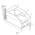
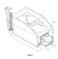
- Figure 4 is a spray box that houses the principal components of the cleaning system, depicted in a left perspective view and Figure 5 is a right perspective view of the spray box of Fig. 4;
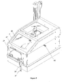
- Figure 6 illustrates a vacuum chuck component of the invention used to hold a wafer, shown from the left side in a withdrawn position from the housing; and Figure 7 illustrates the vacuum chuck component of Fig. 6 from the right side;
- Figure 8 illustrates the foregoing spray box of Fig. 4 and the vacuum chuck of Fig. 6 in a front view with the vacuum chuck extending through the door way of the spray box;
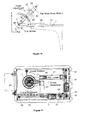
- Figure 9 shows the aspirating nozzle element of the system
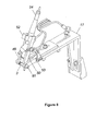
- Figure 10 is a side view of the aspirating nozzle of Fig. 9 and the associated support structure;
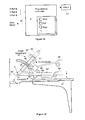
- Figure 11 partially illustrates the wafer cleaning system in a top view overall with the walls of the spray box being treated as transparent;
- Figure 12 partially illustrates the wafer cleaning system of Fig. 11 in side view
- Figure 13 partially illustrates the wafer cleaning system of Fig. 11 in front view
- Figure 14 is a block diagram of the additional controls employed in the practical embodiment of Figs. 4-13;
- Figure 15 illustrates an alternative nozzle and support structure assembly to that shown in Fig. 10;
- Figure 16 illustrates another embodiment of the invention that combines the features of a number of alternative embodiments.
- Figure 17 illustrates the movement undertaken by the nozzle and vacuum chuck elements of one of the embodiments of the invention included in Fig. 16 and is presented to aid in the description of operation.
- the cleaning system includes a vacuum chuck 1 and a fluid nozzle 3 that are coupled, as hereafter described in greater detail, to a three axis positioner 5, X-axis, Y-axis and theta (rotation) axis positioning, all of which components are contained within a housing 7, represented by dash lines, and a programmed controller 9 that controls operation of the positioner.
- a semiconductor wafer 11, represented as having a rectangular geometry is illustrated seated upon chuck 1, for the purpose of assisting in the description of operation, later herein presented, it being understood that the wafer is not a component of the apparatus, but is to be acted upon by the apparatus.
- the sides of the wafer labeled "a” and “b” are designated as the front and back edges of the wafer, respectively, and the sides labeled “c” and “d” are designated as the left and right side edges, respectively, of the wafer.
- the foregoing designation is arbitrary and is solely for the purpose of providing reference locations helpful in the description of operation of the invention.
- Positioner 5 is controlled by a programmed controller 9, which may be a micro-controller that is operated in accordance with a hard-wired program in read-only memory (“ROM”) or a general purpose computer programmed with software to carry out the described functions.
- the positioner is illustrated as a servo-motor driven belt type system for the X and Y axis positioning and a pneumatic stepper motor for theta (rotation).
- a continuous loop belt 10 is supported between a pair of pulleys 12 and 13, and the belt is moved by a servo-motor 15 that turns the pulley 13.
- the positioner includes a second continuous loop belt 19 mounted between a pair of pulleys 20 and 21 with the rotational position of pulley 21 being controlled by a second servo-motor 23.
- a bracket 25 which is slip mounted to a rail 27, vertically oriented in the figure, that supports the weight of the bracket, and, in turn, also the weight of the object to be positioned along the Y-axis, which in this embodiment includes vacuum chuck 1 and some additional elements hereafter described, is coupled to a position along the belt 19.
- belt 19 moves a predetermined distance, back or forth (along the Y-axis)
- the belt pulls bracket 25, which functions as a traveler, the same distance.
- the positioner also includes a rotational axis position control for the object that is to be rotationally positioned, here the object being the vacuum chuck 1 (and any wafer 11 that may be held by the chuck).
- the rotational or, as variously termed ⁇ , positioning is represented in the figure by a pneumatic stepper motor 29, also controlled by controller 9 via an electric gas valve 30, and a gear 31 that engages the gear teeth, not illustrated, of a rotational table, not illustrated, that supports vacuum chuck 1.
- Stepper motor 29, the gear and rotational table are also supported and carried by bracket 25.
- a flexible gas hose extends from valve 30 to the stepper motor.
- Valve 30 connects via a gas line 32 to a source of pressurized gas, not illustrated, suitably the same gas source as is used for nozzle 3, as later herein described.
- Controller 9 connects to gas valve 30 via electrical leads. The controller controls the opening and closing of gas valve 30, and, hence, the supply of pressurized gas to operate stepper motor 29.
- Controller 9 thus controls the X-axis position of nozzle 3 and the Y-position and angular position of vacuum chuck 1 by supplying the appropriate signals to each of the servo-motors and pneumatic stepper motor in accordance with the program that the controller is to follow.
- computer controlled positioners of the foregoing type are available off-the-shelf and may be adapted for use in the practice of the invention.
- the foregoing embodiment employs a belt-pulley arrangement
- other types of positioners are available that employ worm screw type arrangements instead.
- any such positioner care must be taken to avoid any structure that could generate a spark, since the environment is volatile and flammable.
- the invention may incorporate any type of three-axis programmable computer controlled positioner.
- Nozzle 3 is an aspirating nozzle.
- the nozzle is connected by a flexible gas hose 4 to a source of pressurized gas, not illustrated, such as nitrogen.
- the nozzle is also connected by a flexible fluid hose 6 to a reservoir or source of solvent fluid, not illustrated, such as acetone, which is preferred.
- the bracket 17 supports the nozzle at a vertical elevation above the surface of wafer 11, with the latter is seated on chuck 1.
- the height of the nozzle i.e. The Z-axis position, is preferably manually adjustable (as later herein described in greater detail), and is adjusted to be at a higher elevation than the vacuum chuck 1 and any installed wafer 11.
- the nozzle is positioned with the nozzle axis inclined to the surface of the vacuum chuck 1 and, hence, is inclined to the surface of the wafer 11 that is to be installed and cleaned.
- controller initializes and positions the end of nozzle 3 at the reference 0,0 position set by the designer of the controller program, as example, at the lower left corner of wafer 11 in Fig. 1 or, with an aspirating sprayer as in the preferred embodiment, just below the lower left corner of the wafer.
- an aspirating nozzle such as nozzle 3
- a high velocity stream of gas flows past a fluid inlet in the nozzle and out the nozzle exit.
- the streaming gas With the fluid inlet connected to a source of fluid, the streaming gas lowers the pressure over the inlet and fluid is forced up through the inlet, and into the stream of gas, the known phenomena of aspiration.
- the aspirated fluid then travels with essentially the same velocity and pressure as the gas, and out the nozzle exit.
- the volume or rate at which the fluid is drawn up may be adjusted by adjusting the size of the inlet, which may be accomplished manually.
- the nozzle expresses an aspirated spray of fluid, hereafter sometimes referred to as a fluid jet. Initially, the output of the nozzle is gas, but quickly aspirates the solvent fluid. Hence, except where noted to the contrary the fluid jet is understood to contain both solvent fluid and the gas.
- the nozzle being used in the preferred embodiment is an aspirating type nozzle, that which exits from the nozzle when the system initially is operated is a blast of the aspirating gas. After a few moments the fluid solvent is drawn up and the fluid jet is then expressed from the nozzle. To avoid having the initial gas jet directed onto the wafer surface for reasons later discussed, it is preferred to make the first steps of the spray pattern, namely the first left to right movement (horizontal movement in the figure), be directed slightly in front of the bottom edge of wafer 11 so that the gas stream does not impact the wafer surface. Additionally, an anti-siphon valve may be incorporated in the system to reduce fluid depletion when the system is idle.
- the controller is programmed to move the relative position of the nozzle and wafer in accordance with the pattern of Fig. 2 to which reference is made. As shown in the figure, the nozzle is to follow a path from left to right directing a fluid jet onto the wafer as the nozzle moves. When the right side of the wafer is reached (or thereafter), the direction of the nozzle movement is reversed and, simultaneously, the relative vertical position from the bottom edge of the wafer is increased one small increment. The nozzle then moves from right to left spraying solvent fluid and gas at the wafer along a horizontal path parallel to the prior path taken.
- the direction of movement of the nozzle is again reversed, moving from left to right, and the vertical level, the distance from the front edge of the wafer, is again increased by an increment.
- the foregoing movement is repeated as many times as is necessary for the jet of solvent fluid to at least reach the upper right back corner of the back edge of the wafer (and may extend beyond that horizontal position) at which position wafer cleaning may conclude (or as later herein described be put through additional cleaning).
- Programming the controller to accomplish the foregoing pattern (and any other desired pattern) of movement is elementary to those skilled in the programming arts, the details of which are not necessary to an understanding of the invention.
- the controller supplies the appropriate signal to valve 30 releasing a sufficient number of gas pulses to stepper motor 29 to ensure that the stepper motor positions the zero degree rotational orientation of vacuum chuck 1 to the zero or reference position, if not already at that rotational position.
- Controller 9 supplies a signal to servo-motor 15 that moves belt 11 to the left, and, hence, bracket 17 and nozzle 3, so that the nozzle axis lines up with the left side, side "c" of the wafer, the zero X-reference position. Controller 9 also supplies a signal to servo-motor 21 that moves the belt 19, and, hence, bracket 25 and vacuum chuck 1, forward in the figure, so that the front edge "a" of wafer 11 aligns with the Y-axis zero reference position. At that reference position, the fluid jet issuing from the elevated end of nozzle 3 strikes the surface of the wafer at a position just in front of the front edge of the wafer, for reasons earlier discussed. With other types of sprayers, the position of the strike would be at the front edge. As a practical matter, the distance is at most a minute distance from the front exit end of nozzle 3, and, one may state (with acceptable slight inaccuracy) that the front end of the nozzle 3 essentially lies on the Y-axis zero reference position.
- the controller then starts the sweeping procedure, supplying positioning information to move the nozzle 3 from the left to the right side edge of the wafer.
- the controller supplies a signal to the Y-axis servo motor 29 to move the vacuum chuck 1 a predetermined small increment downward (in the figure), placing the end of nozzle 3, as example, a small distance above the front edge of the wafer; and the controller thereafter supplies signals to the X-axis servo-motor 13 to continuously move the nozzle parallel to the X-axis to the left.
- the controller again operates the Y-axis servo motor to move the chuck downward (in the figure) an additional increment and reverses the direction of travel of nozzle 3, which proceeds from left to right.
- the foregoing operation continues until the fluid jet from the nozzle reaches at least the upper right hand corner of wafer 11.
- the fluid jet from the nozzle is applied to the surface of the wafer from side to side and from front to back of the wafer, covering the entire surface of the wafer.
- the axis of nozzle 3 is inclined to the surface of the wafer 11 and vacuum chuck 1, while the nozzle is elevated slightly above the surface of the wafer.
- the incline may at an angle selected from a range of about twenty degrees to seventy degrees.
- the aspirated spray of solvent fluid is expressed from the nozzle under considerable pressure, the pressure of the aspirating gas stream, and at a high velocity.
- the fluid jet strikes the surface of the wafer askance with considerable impact. Should a particle (or particles) be present on the surface and be struck by the fluid jet, the fluid exerts a force sufficient to push the particle (or multiple particles) forward along the surface of the wafer.
- the particles are pushed forward in the same direction as the nozzle travels relative to the surface of the wafer and, hence, the fluid jet. Hence, as the nozzle continues movement toward the back edge of the wafer in the line by line movement, the particles as may have accumulated on the disk (and not pushed off) are pushed further forward by force of the jet. As the nozzle moves along the back edge of the wafer, any accumulated are eventually pushed off the back edge of the wafer and fall onto the vacuum chuck and/or to the bottom of housing 7.
- the nozzle In pushing particles forward, the nozzle, in effect acts as a broom, albeit, a hydraulic one. By routing the hydraulic broom over the surface, the broom sweeps the surface of the wafer.
- the foregoing action resembles the process used by one to sweep fallen leaves from one's home driveway by "hosing down", cleaning, one's driveway with a stream of water from the garden hose, another hydraulic broom.
- the controller may be programmed to have the hydraulic broom travel a predetermined distance beyond the side edges of the wafer and/or the front and back edges of the wafer. Although doing so perhaps somewhat simplifies the programming of the controller, the extra movement beyond the edges of the wafer serves no purpose and is not preferred. The extra movement increases the time taken to sweep the wafer. Such extra relative movement of nozzle 3 delays the cleaning of the next wafer to be cleaned and thereby delays production.
- the spray of fluid solvent creates a considerable amount of splashing upon striking the wafer surface.
- the splashed fluid is confined within housing 7, and serves to clean particles from the exposed portions of the vacuum chuck not covered by the wafer, and washes down to the bottom of the housing.
- controller 9 to accomplish the routing of nozzle 3 relative to the surface of the wafer during cleaning is a preferred routing.
- Other routing may be substituted in the practice of the invention, even if that routing is less preferred.
- the controller may be programmed to route the nozzle in the zig-zag pattern illustrated in Fig. 3 to which reference is made. In order to follow the zig-zag path the nozzle must be moved not only along the X-axis, but simultaneously along the Y-axis as well. Returning to Fig.
- controller 9 supplies signals to both servo-motor 15, which drives the nozzle movement along the X-axis concurrently with servo-motor 23, which drives the vacuum chuck along the Y-axis (or as alternatively viewed moves nozzle 3 in the Y-direction relative to chuck 1), but at a lesser incremental movement.
- wafer 11 has been described implicitly as having a relatively flat surface, which is accurate as viewed on a macroscopic level.
- the surface of the wafer during fabrication of semiconductor chips acquires a definite topology of some regions that are vertically higher than other regions.
- Fabrication of the chips on the wafer involves producing multiple layers of metals, and differently doped layers of semiconductor materials, which is accomplished in multiple fabrication steps. Upon completion of each step, the wafer must be cleaned before beginning the next step or stage of fabrication. In the later stages of chip manufacture, the surface of the wafer contains a definite topology.
- the fluid jet When cleaning the wafer in the later stages of semiconductor chip fabrication, a possibility exists that the fluid jet will be unable to force a microscopic size particle up over an adjacent a microscopic size "wall" or may press the particle against that wall when that wall lies perpendicular to the direction of the solvent fluid jet from nozzle 3. Hence, despite the foregoing cleaning, the wafer may retain some particles and thereby remain unclean.
- the foregoing wall By reorienting the wafer to another angle, such as by reorienting the wafer by ninety degrees, the foregoing wall will then lie parallel to the direction of the fluid jet. In that orientation, the fluid jet will easily push the particle forward alongside the wall.
- the present invention provides for rotating the wafer to another angular position so as to minimize or avoid retaining microscopic particles due to the foregoing microscopic walls in the wafer.
- the forward edge "a" of the wafer is located at a lower horizontal position in the figure than the rear edge "b" and nozzle 3 essentially traveled from the lower left corner of wafer 11 to the upper right corner of the wafer.
- controller 9 determines that the wafer cleaning procedure is completed, that is, according to the tracking of the program by the computer (in lieu of active position monitoring) nozzle 3 should essentially be located at the upper right corner of the wafer (formed at the juncture of sides "b" and "d” in the figure), controller 9 supplies appropriate signals to electrically operated gas valve 30, which in turn, supplies gas pulses to the theta pneumatic stepper motor 29, commanding the stepper motor 29 to rotate clockwise, as example, by an angle of ninety degrees. Stepper motor 29 then rotates the vacuum chuck 1 about the axis of the chuck by ninety degrees.
- controller 9 operating servo-motors 15 and 23, repositions the vacuum chuck 1 and the nozzle 3 (as in the initialization procedure earlier described) so that the fluid jet from the nozzle is again directed at the lower left corner of the repositioned wafer 11 and repeats the cleaning process which was earlier described and need not be repeated.
- controller 9 may in alternate embodiments be programmed to rotate the wafer by any other angle several times, repeating the cleaning process each time.
- the program may call for rotating the wafer by an increment of 45 degrees each time the cleaning process is completed, re-run the cleaning process and to perform such rotations and re-run the cleaning process two additional times, a total of 135 degrees, before concluding the cleaning procedure for the wafer.
- the alternative programs are less preferred as they require additional time for cleaning and, thus slow down the semiconductor fabrication process and appear to go beyond the point of diminishing return in cleaning.
- a pneumatic motor 29 the rotation of the vacuum chuck was controlled by a pneumatic motor 29. It is appreciated that other means may be substituted for that type of motor, as example, a brushless electric motor, such as a servo-motor, such as used for motors 15 and 23.
- the controller On concluding the cleaning of a wafer, the controller halts the operation and extends the water chuck beyond the housing so that the cleaned wafer may be removed.
- Another wafer may be loaded for cleaning by aligning the wafer in the chuck so that the axis of the wafer is preferably aligned with the chuck axis and an edge of the wafer is aligned with the Y-axis traveled by nozzle 3.
- Figs. 4 and 5 illustrate housing 7.
- the housing includes a bottom hinged front door 34, which pivots open like an oven door, to provide access, and, above the door, a glass or transparent plastic window 35, through which personnel may view the wafer during the cleaning operation.
- the door is pneumatically operated under control of the programmed controller.
- Hose 37 supplies pressurized nitrogen to open hinged door 34 and hose 38 supplies pressurized nitrogen to close that door.
- Hose 36 supplies acetone to the external drip 47, which is attached to the enclosure.
- Hose 39 attaches to an appropriate exhaust vent, not illustrated, at the rear of the housing, and connects to the facility gas exhaust system, which typically may be a thermal oxidizer for solvent use or a fume exhaust for a non-solvent use.
- the shielded electrical conduit 40 is the electrical signal interface from the controller 9 to the x-axis stepper motor.
- Hose 41 supplies pressurized nitrogen to purge or vent the plenum in which the brushless X and Y-axis stepper motors are located.
- the housing may be fabricated of stainless steel or aluminum. Automated wafer cleaning is accomplished inside the housing, which contains the splashing of the solvent fluid to the closed internal region of the housing.
- Figs. 6 and 7 illustrate vacuum chuck 1 from the left and right sides, respectively, in a position withdrawn from housing 7 for insertion or removal of a wafer.
- the vacuum chuck is advanced forward out of housing 7 to the illustrated "home" position.
- Hose 42 is the vacuum hose that supplies the suction on the upper surface that holds the wafer in place.
- Hose 43 is the gas hose to the pneumatic stepper motor, not visible in the figure. The outer surface of stepper motor 29 and bracket 25 are more visible in Fig. 7.
- the vacuum chuck is seen in a top perspective view in Fig. 9 to which reference is made.
- a conduit 47 is shown attached to the front of housing 7.
- the conduit contains an open end positioned over the center of the surface of the vacuum chuck, when the latter is in the extended position shown in the figure.
- the conduit connects to a pressurized reservoir of the acetone cleaning fluid supplied in a common acetone distribution manifold as may be located immediately behind the enclosure.
- the conduit is calibrated to drip acetone fluid onto the vacuum chuck and/or wafer placed on the chuck and is referred to as the external acetone drip.
- the cleaning fluid keeps the organic contaminants on the wafer from drying, which would make those contaminants more difficult to remove in the cleaning process.
- Figs. 8 and 10 illustrate the spray apparatus in perspective and in side view, respectively.
- Nozzle 3 is supported to the inverted "L" shaped bracket 17 by adjustment brackets 49 and 50.
- the bracket arms 49 are pivotally connected together at pivot axis 51.
- the nozzle is clamped between the two arms by clamping members 52 attached to the upper end of the arms 49.
- the nozzle 3 contains a long generally cylindrical body.
- the upper end contains a valve mechanism 54 that permits manually adjusting the force of the fluid spray or jets that issue from the opening at the lower end.
- Nozzles of the foregoing type are available from various sources as an off-the-shelf item.
- Bracket arm 50 contains a slotted upwardly extending curved guide arm 53.
- the curved slot is a sector of a circle.
- Arm 49 is pivoted to the appropriate angle desired relative to the horizontal, suitably between about twenty to seventy degrees in the preferred embodiment, and the arm 49 is secured to that position of the guide arm 53 by tightening a bolt and nut through the slot.
- the nozzle may be moved along the nozzle axis 56 either forward or backward prior to tightening the clamping members 52 to either reduce or increase the distance from the nozzle end to the surface of the vacuum chuck, hence, to the wafer.
- the foregoing constitutes a manual Z-axis adjustment.
- Fig. 11 illustrates the wafer cleaning system in a top view
- Fig. 12 illustrates that system in side view
- Fig. 13 is a front view of the wafer cleaning system.
- the housing is rendered as transparent with the outline of the housing elements illustrated in order to permit view of the internal components. All of the elements earlier described contain the same denomination as in the previous figures.
- a drain 57 is included on the bottom of the housing.
- the drain is connected to an appropriate solvent collection tank in the facility. All of the particles removed, and dissolved organic material and acetone fluid during cleaning is removed from the housing assembly through that drain.
- Fig. 14 is a block diagram of the control circuit and additional apparatus for this feature.
- the programmed controller 9 incorporates an operator selection key pad. To start the operation the operator need only momentarily depress the start switch associated with the cleaning program that is to be run (only one being illustrated in the figure). At the conclusion of cleaning the controller is programmed to output a perceptible signal to personnel as at alarm 61. Responding to that signal the personnel, would then depress the exit key. The controller is programmed to respond to the depression of the exit key by issuing a signal to the door motor to open the door. Door 34 then opens, such as was illustrated in Figs. 6-8.
- the controller is also programmed to follow the door opening to move the vacuum chuck 1 to an extended position outside the housing as shown in the cited figures by supplying the appropriate signal to the Y axis servo-motor.
- the belt 19 and rail in the Y-axis direction extends to the front of the housing.
- bracket 25 moves to the far left in the figure
- the vacuum chuck, located on a foot of the L-shaped bracket will extend out of the housing.
- the stop button permits the operator to halt the cleaning at any time at the operator's discretion.
- the cleaning system may be programmed to permit the depression of the start button to initialize from the open door position just described.
- the operator may remove the cleaned wafer and install another wafer on the vacuum chuck.
- the controller may be programmed to move the vacuum chuck inside the housing 7, and then relatively move the nozzle and chuck as earlier described in this specification. The controller would then issue a signal to the door motor to close the door. Cleaning would then commence.
- the nozzle 3 is placed about one to five centimeters above the surface of the wafer; the axis of the nozzle is inclined at an angle of about 20 to 70 degrees to the surface of wafer 11, as example, forty-five degrees.
- the fluid solvent expressed through nozzle 3 in the axial direction of the nozzle is under a pressure of about 20 to 100 psi.
- Acetone is a preferred solvent for cleaning of wafers, even though the fluid is flammable and in the vapors found in the operation could be explosive.
- the system avoids any component that might produce a spark.
- the system includes brushless motors, the servo-motors, which do not contain any brushes which are likely to produce sparks.
- the plenum in which those motors are located is purged with nitrogen supplied through hose 41.
- the system also includes a pneumatically operated stepper motor.
- the atmosphere within housing 7 is ventilated to an external ventilation system that draws off and disposes of any vapors harmlessly.
- the invention has been described in connection with a rectangular wafer, as one appreciates, the invention is not limited to cleaning of wafers that are of a square or rectangular shape. As those skilled in the art recognize the invention is capable of cleaning wafers that may be of any shape.
- the closest portion or point of the periphery of the wafer that is at the lowest vertical position in the figure should be regarded as the front edge; and that portion or point at the highest vertical position in the figure should be regarded as the back edge or side of the wafer; and likewise the left side edge would be the point or portion of the periphery of the wafer located at the horizontal position in the figure located closest to the left edge of the sheet; and the right side edge would be the point or portion of the periphery of the wafer located farthest horizontal position from the left edge of the sheet.
- the relative movement between the nozzle and the wafer provides a scan or sweep of the entire surface of such a circular or elliptical shaped wafer in the same manner as occurs with the rectangular shaped wafer.
- the movement of the hydraulic broom is relative movement.
- the chuck carrying the wafer, and, hence, the wafer is moved in one axial direction and the nozzle is moved in an orthogonal direction to produce the "sweeping" action of the nozzle in the X-Y plane over the entire surface of the wafer.
- the nozzle is supported on a bracket that is manually adjustable, as illustrated in Fig. 10, to which brief reference is made.
- a bracket that is manually adjustable, as illustrated in Fig. 10, to which brief reference is made.
- a more highly automated nozzle and support assembly such as illustrated in side view of Fig. 15, may be substituted.
- the elements that are incorporated in the assembly of Fig. 15 that correspond to elements in the manually adjustable assembly of Fig. 10 are identified by the same number, primed, and the description need not be repeated.
- the arcuate slot is used merely as a guide for the pivotal movement of bracket 49', eliminating the nut of the clamping bolt associated with the slot.
- the platform 50' is supported atop the inverted L-shaped bracket by a pneumatic actuator 58, pictorially illustrated.
- the movable portion of actuator 58 is attached to the underside of the platform and is strong enough to support the entire assembly.
- Another pneumatic actuator 59 pictorially illustrated, is pivotally anchored to the upper surface of platform 50' and its extensible portion is attached to the bracket 49' supporting nozzle 3'.
- Actuator 58 is connected by hose 69 to an output peripheral of controller 9, and actuator 59 is similarly connected by hose 68.
- the controller controls the vertical (Z-axis) position of the tip of nozzle 3' above the L-shaped pedestal.
- the actuator is able to either pivot the bracket 49', and nozzle 3' to the left about the pivot point, increasing the angle ⁇ , the angle of tilt, or pivot the bracket down to the right in the figure, decreasing that angle.
- a height sensor 60 is connected to an input, not illustrated, of the controller to provide feedback to the controller of the height.
- a tilt sensor 67 pictorially illustrated, is connected to another input, not illustrated, of the controller and provides feedback to the controller of the tilt angle.
- the controller is programmed to process the respective height and angle information, determine if the height and inclination are achieved and actuate the respective pneumatic adapters to do so.
- a pneumatic motor 29 was used to position the spindle or vacuum chuck 1 at various angles of rotation under control of the programmed controller 9.
- the pneumatic motor is replaced with another electric motor 63 of a type that does not produce electrical sparks; and that motor is controlled by programmed controller 9' as represented by the control line leading thereto.
- Electric motor 63 may position the vacuum chuck at any angle of rotation, essentially performing the same functions as pneumatic motor 63 of the prior embodiment.
- the controller 9' may provide a control input that requires electric motor 63 to rotate or spin continuously for a predetermined duration prescribed by the program of the controller.
- Such continuous rotation serves an additional function in the spray cleaner combination.
- the spray cleaning apparatus is used to spray clean wafer 11' in the manner previously described.
- the controller 9' is programmed to operate motor 63 continuously for a selected interval. In so doing, the motor spins vacuum chuck 1' at a high rotational rate to spin-dry the wafer. The high centrifugal force created by spinning forces any liquid on the wafer to be thrown off. Following completion of the foregoing spin dry operation, the controller then terminates spray cleaning operation.
- Fig. 1 contained a single spray nozzle.
- a further alternative embodiment of the invention may contain more than one spray nozzle.
- a second spray nozzle 64 is included in the combination. That additional spray nozzle is supported on a bracket that is joined to bracket 17' that supports nozzle 3', and, hence, moves in unison with the latter nozzle and vice-versa.
- Spray nozzle 64 is coupled by a flex hose to a source of de-ionized water ("Dl water”) and/or methanol as is indicated in the figure.
- Dl water de-ionized water
- controller 9' is programmed to connect the Dl water to the hose, through a valve, not illustrated, upon conclusion of the cleaning step described in connection with the operation of the embodiment of Fig. 1.
- the controller may be programmed to repeat the relative movement of nozzle 64 over the entire disk, as occurred in the case of the spray cleaning or position the nozzle at a strategic position relative to wafer 11' and then allowed to remain open, spraying out the Dl water (or, as appropriate, methanol).
- the Dl water (or, as appropriate, methanol) thereby rinses off wafer 11'.
- the spray cleaning apparatus is constructed and programmed to include both the additional nozzle structure and rinse cycle as well as the continuous spin motor and spin-dry cycle described in the immediately preceding paragraphs. In that way, following the spray cleaning of the wafer, the wafer is rinsed and spin-dried.
- controller 9' is programmed to initially position spray cleaning nozzle 3' at the center of the vacuum spindle 1' on commencement of the spray cleaning of wafer 11'. Then motor 63 is commanded by controller 9' to spin continuously so that the wafer 11' spins with a rotational speed from about ten to 500 revolutions per minute. Concurrently, the controller slowly operates motor 15' to move nozzle 3' laterally to the right to the outer edge of the wafer.
- the foregoing relative movement between wafer 11' and nozzle 3' is more of a polar coordinate system of movement in lieu of the Cartesian system described in connection with the operation of Fig. 1.
- the foregoing movement does not require movement of Y-axis positioner motor 20'.
- a form of the apparatus could be designed that eliminated that positioner.
- the preferred form is to retain the Y-axis movement capability in a single apparatus to allow the spray cleaning apparatus to possess a maximum flexibility for programmed operation.
- nozzle 3' is supported by a positioner motor 66' that in turn is controlled by controller 9' as represented by the control line.
- controller 9' When energized, positioner motor 66' turns and thereby changes or adjusts the angular orientation of the axis of spray nozzle 3'.
- controller 9' is programmed to initially position spray cleaning nozzle 3' at the center of the vacuum spindle 1' on commencement of the spray cleaning of wafer 11'.
- motor 63' is commanded by controller 9' to spin continuously so that the wafer 11' spins with a rotational speed from about ten to 500 revolutions per minute.
- controller 9' slowly operates motor 15' to move nozzle 3' laterally to the right to the outer edge of the wafer and operates motor 66' to periodically sweep nozzle 3' over an angle of 180 degrees, back and forth.
- Fig. 17 The foregoing motion is illustrated in Fig. 17 to which reference may be made.
- the nozzle is pivoted over an arc, the pivot point being formed on a bracket, not illustrated. That allows the nozzle to be directed in different directions. All the while the bracket, not illustrated, holding the nozzle and the pivot point is being carried forward along the linear path indicated by dash lines. Simultaneously the vacuum chuck is being rotated about its axis at varying rates ⁇ .
- the foregoing angular reciprocation of the nozzle and its movement along the X-axis with simultaneous spinning of the vacuum chuck 1' ensures a good cleaning of the wafer.
- nozzle 3 in the embodiment of Fig. 1 may be replaced by multiple spray nozzles, each of which is connected to the supply of fluid and gas to which nozzle 3' is connected.
- the multiple nozzles are spaced laterally so as to cover different portions of wafer 11.
- the cleaning apparatus may be enhanced further by the incorporation of a suitable robotics system for loading and unloading of the wafer in the cleaning apparatus, such as the familiar cassette to cassette wafer transfer system, in lieu of the manual system described in connection with Fig. 1.
- a suitable robotics system for loading and unloading of the wafer in the cleaning apparatus, such as the familiar cassette to cassette wafer transfer system, in lieu of the manual system described in connection with Fig. 1.
- a cleaning system for spray cleaning wafers one at a time.
- spray cleaning of a number of wafers may be accomplished with the invention by enlarging the housing for the apparatus and providing multiple numbers of elements for handling multiple wafers simultaneously, all of which comes within the scope of the invention.
- a plurality of vacuum chucks may be operated in tandem by a single Y-axis positioner and a plurality of nozzles, one or more associated with each of the plurality of vacuum chucks, are supported by an X-axis position for joint movement, which is operated under control of a single controller.
- Each of the nozzles would be connected to the fluid and gas hoses (described in Fig. 1) and the housing is enlarged in size to accommodate all such elements.
- a wafer may be placed in each vacuum chuck, and cleaning operation commenced. The cleaning operation is essentially the same as described for cleaning a single wafer.
- a like tandem arrangement for cleaning a plurality of wafers simultaneously may be employed for each of the alternative embodiments previously described.
Abstract
Description
- This invention relates to cleaning of semiconductor wafers, including Germanium, Silicon and all other semiconductor compounds, such as Gallium Arsenide ("GaAs") and Indium Phosphide ("InP") and, more particularly, to a method and apparatus for thoroughly spray cleaning the surface of semiconductor wafers of particulate and organic contaminants in a manner that assures uniform and reproducible cleanliness of each wafer cleaned.
- Semiconductor devices are typically fabricated on single crystal wafers of semiconductor materials using photo-lithographic mask and etch or ion-bombardment techniques. Typically the wafer contains a large number of semiconductor devices which are fabricated simultaneously. Initially, and at the completion of each step in the semiconductor fabrication process, some residue remains; the kind or type of residue being in part dependent on the stage of fabrication processing, and the wafer surface must be cleaned in preparation for a succeeding step. Depending upon the particular process step in the semiconductor device fabrication process being completed, the completion of a particular process step may incidentally also produce particulate debris, organic contaminants and/or unwanted pieces of thin film metallization layers on the surface of the semiconductor wafer. The residue, particulate debris, organic contaminants and metal pieces must be removed before proceeding with the next step in the fabrication process.
- Mass produced semiconductors typically employ silicon technology and cleaning equipment exists to handle such mass production. Such cleaning equipment, however, is unsuited to semiconductors that use the III-V compounds identified in the Periodic Table of the Elements, such as InP and GaAs. First, cleaning solvents used for cleaning silicon wafers are either strong acids or strong bases, which are very harsh chemicals inappropriate for InP and GaAs wafers and produces a lower overall cleanliness. As an advantage, the present invention avoids harsh chemicals detrimental to the wafer. Second, the semiconductor chips produced on silicon wafers are not as fragile as the semiconductor chips fabricated on InP or GaAs wafers. Certain cleaning apparatus designed for cleaning of silicon wafers, such as brush scrubbing, produces structural damage when applied to cleaning of semiconductor devices constructed on InP or GaAs or other compound semiconductor wafers, especially for wafers containing gold metallization layers. As an advantage, the present cleaning system is less harmful mechanically to the semiconductor chips on the wafer.
- Accordingly, a principal object of the invention is to clean wafers fabricated of compound semiconductors in a uniform and reproducible manner.
- Another object of the invention is to clean Silicon and Germanium wafers or other types of substrates that employ devices or structures the could be damaged by application of conventional cleaning techniques.
- A further object of the invention is to minimize and conserve the consumption of solvent and reduce the hazardous waste generated in the semiconductor cleaning process.
- A still further object of the invention is to provide a computer controlled wafer cleaning apparatus that assures that each wafer cleaned is cleaned exactly alike.
- And still another object of the invention is to provide an automated wafer cleaning apparatus that is relatively inexpensive to build and operate, may be constructed of "off-the-shelf" components, is easy to maintain, and may operate in an essentially unattended manner.
- In accordance with the foregoing objects and advantages, semiconductor wafers are cleaned by moving a hydraulic broom about the surface of the wafer to sweep the wafer clean, the pressurized fluid issuing from the hydraulic broom being of a character that dissolves organic solvents as may be present on the surface of the wafer and produces the mechanical force to dislodge particulate debris from the wafer. In accordance with a specific aspect to the invention, the hydraulic broom is formed of an aspirated sprayer which combines gas released from a pressurized source of gas, suitably nitrogen, through a nozzle and aspirating the cleaning fluid, suitably acetone, through the nozzle into the gas stream providing a source of pressurized cleaning fluid expressed from the nozzle.
- The cleaning system is automated. In one embodiment a three-axis positioner, under control of a programmed controller, controls the sweep of the hydraulic broom, moving the broom in a predefined "scanning" pattern over the wafer surface. As an advantage, the pattern of scan may be changed, the number of cleanings of an individual wafer may be changed, and the orientation of the wafer may be changed to permit a surface sweep in an alternate direction. In another embodiment polar movement is employed rotating the wafer while simultaneously continuously pivoting the broom over a predetermined arc about a pivot axis and linearly translating the position of that pivot axis.
- The foregoing and additional objects and advantages of the invention together with the structure characteristic thereof, which was only briefly summarized in the foregoing passages, will become more apparent to those skilled in the art upon reading the detailed description of a preferred embodiment of the invention, which follows in this specification, taken together with the illustrations thereof presented in the accompanying drawings.
- In the drawings:
- Figure 1 illustrates a wafer cleaning system in accordance with the invention;
- Figure 2 illustrates a preferred routing program of the relative movement of the wafer and spray nozzle elements in the operation of the embodiment of Fig. 1;
- Figure 3 illustrates another less preferred routing of the relative movement of the wafer and nozzle elements in the embodiment of Fig. 1;
- Figure 4 is a spray box that houses the principal components of the cleaning system, depicted in a left perspective view and Figure 5 is a right perspective view of the spray box of Fig. 4;
- Figure 6 illustrates a vacuum chuck component of the invention used to hold a wafer, shown from the left side in a withdrawn position from the housing; and Figure 7 illustrates the vacuum chuck component of Fig. 6 from the right side;
- Figure 8 illustrates the foregoing spray box of Fig. 4 and the vacuum chuck of Fig. 6 in a front view with the vacuum chuck extending through the door way of the spray box;
- Figure 9 shows the aspirating nozzle element of the system;
- Figure 10 is a side view of the aspirating nozzle of Fig. 9 and the associated support structure;
- Figure 11 partially illustrates the wafer cleaning system in a top view overall with the walls of the spray box being treated as transparent;
- Figure 12 partially illustrates the wafer cleaning system of Fig. 11 in side view;
- Figure 13 partially illustrates the wafer cleaning system of Fig. 11 in front view;
- Figure 14 is a block diagram of the additional controls employed in the practical embodiment of Figs. 4-13;
- Figure 15 illustrates an alternative nozzle and support structure assembly to that shown in Fig. 10;
- Figure 16 illustrates another embodiment of the invention that combines the features of a number of alternative embodiments; and
- Figure 17 illustrates the movement undertaken by the nozzle and vacuum chuck elements of one of the embodiments of the invention included in Fig. 16 and is presented to aid in the description of operation.
- Reference is made to the pictorial illustration of Fig. 1, illustrating a wafer cleaning system constructed in accordance with the invention. The cleaning system includes a
vacuum chuck 1 and afluid nozzle 3 that are coupled, as hereafter described in greater detail, to a threeaxis positioner 5, X-axis, Y-axis and theta (rotation) axis positioning, all of which components are contained within ahousing 7, represented by dash lines, and a programmedcontroller 9 that controls operation of the positioner. - A
semiconductor wafer 11, represented as having a rectangular geometry is illustrated seated uponchuck 1, for the purpose of assisting in the description of operation, later herein presented, it being understood that the wafer is not a component of the apparatus, but is to be acted upon by the apparatus. For purposes of discussion the sides of the wafer labeled "a" and "b" are designated as the front and back edges of the wafer, respectively, and the sides labeled "c" and "d" are designated as the left and right side edges, respectively, of the wafer. The foregoing designation is arbitrary and is solely for the purpose of providing reference locations helpful in the description of operation of the invention. -
Positioner 5 is controlled by a programmedcontroller 9, which may be a micro-controller that is operated in accordance with a hard-wired program in read-only memory ("ROM") or a general purpose computer programmed with software to carry out the described functions. The positioner is illustrated as a servo-motor driven belt type system for the X and Y axis positioning and a pneumatic stepper motor for theta (rotation). - In such a positioner a
continuous loop belt 10 is supported between a pair ofpulleys motor 15 that turns thepulley 13. Abracket 17, which is slip mounted to astraight rail 16, oriented horizontal in the figure, that supports the weight of the bracket, and, in turn, also the weight of the object to be positioned along the X-axis, which isnozzle 3 in this embodiment, is coupled to a position along the belt. Whenbelt 10 moves a predetermined distance, back or forth (along the X-axis), the belt pullsbracket 17, which functions as a traveler, the same distance. - The positioner includes a second
continuous loop belt 19 mounted between a pair ofpulleys pulley 21 being controlled by a second servo-motor 23. Abracket 25, which is slip mounted to arail 27, vertically oriented in the figure, that supports the weight of the bracket, and, in turn, also the weight of the object to be positioned along the Y-axis, which in this embodiment includesvacuum chuck 1 and some additional elements hereafter described, is coupled to a position along thebelt 19. Whenbelt 19 moves a predetermined distance, back or forth (along the Y-axis), the belt pullsbracket 25, which functions as a traveler, the same distance. - The positioner also includes a rotational axis position control for the object that is to be rotationally positioned, here the object being the vacuum chuck 1 (and any
wafer 11 that may be held by the chuck). The rotational or, as variously termed , positioning is represented in the figure by apneumatic stepper motor 29, also controlled bycontroller 9 via anelectric gas valve 30, and agear 31 that engages the gear teeth, not illustrated, of a rotational table, not illustrated, that supportsvacuum chuck 1.Stepper motor 29, the gear and rotational table are also supported and carried bybracket 25. A flexible gas hose extends fromvalve 30 to the stepper motor. - Valve 30 connects via a
gas line 32 to a source of pressurized gas, not illustrated, suitably the same gas source as is used fornozzle 3, as later herein described.Controller 9 connects togas valve 30 via electrical leads. The controller controls the opening and closing ofgas valve 30, and, hence, the supply of pressurized gas to operatestepper motor 29. -
Controller 9 thus controls the X-axis position ofnozzle 3 and the Y-position and angular position ofvacuum chuck 1 by supplying the appropriate signals to each of the servo-motors and pneumatic stepper motor in accordance with the program that the controller is to follow. As those skilled in the art appreciate, computer controlled positioners of the foregoing type are available off-the-shelf and may be adapted for use in the practice of the invention. - Further, although the foregoing embodiment employs a belt-pulley arrangement other types of positioners are available that employ worm screw type arrangements instead. However, with any such positioner care must be taken to avoid any structure that could generate a spark, since the environment is volatile and flammable. As is appreciated, the invention may incorporate any type of three-axis programmable computer controlled positioner.
-
Nozzle 3 is an aspirating nozzle. The nozzle is connected by aflexible gas hose 4 to a source of pressurized gas, not illustrated, such as nitrogen. The nozzle is also connected by a flexiblefluid hose 6 to a reservoir or source of solvent fluid, not illustrated, such as acetone, which is preferred. Thebracket 17 supports the nozzle at a vertical elevation above the surface ofwafer 11, with the latter is seated onchuck 1. The height of the nozzle, i.e. The Z-axis position, is preferably manually adjustable (as later herein described in greater detail), and is adjusted to be at a higher elevation than thevacuum chuck 1 and any installedwafer 11. Additionally, the nozzle is positioned with the nozzle axis inclined to the surface of thevacuum chuck 1 and, hence, is inclined to the surface of thewafer 11 that is to be installed and cleaned. - For operation,
wafer 11 is seated on thevacuum chuck 1 inhousing 7 with the front edge of the wafer aligned with the X-axis, parallel to rail 19, and the vacuum source, not illustrated is connected to the chuck to hold the wafer in place. Controller initializes and positions the end ofnozzle 3 at thereference wafer 11 in Fig. 1 or, with an aspirating sprayer as in the preferred embodiment, just below the lower left corner of the wafer. - In an aspirating nozzle, such as
nozzle 3, a high velocity stream of gas flows past a fluid inlet in the nozzle and out the nozzle exit. With the fluid inlet connected to a source of fluid, the streaming gas lowers the pressure over the inlet and fluid is forced up through the inlet, and into the stream of gas, the known phenomena of aspiration. The aspirated fluid then travels with essentially the same velocity and pressure as the gas, and out the nozzle exit. The volume or rate at which the fluid is drawn up may be adjusted by adjusting the size of the inlet, which may be accomplished manually. With both the solvent fluid and the source of gas connected to the nozzle, the nozzle expresses an aspirated spray of fluid, hereafter sometimes referred to as a fluid jet. Initially, the output of the nozzle is gas, but quickly aspirates the solvent fluid. Hence, except where noted to the contrary the fluid jet is understood to contain both solvent fluid and the gas. - Because the nozzle being used in the preferred embodiment is an aspirating type nozzle, that which exits from the nozzle when the system initially is operated is a blast of the aspirating gas. After a few moments the fluid solvent is drawn up and the fluid jet is then expressed from the nozzle. To avoid having the initial gas jet directed onto the wafer surface for reasons later discussed, it is preferred to make the first steps of the spray pattern, namely the first left to right movement (horizontal movement in the figure), be directed slightly in front of the bottom edge of
wafer 11 so that the gas stream does not impact the wafer surface. Additionally, an anti-siphon valve may be incorporated in the system to reduce fluid depletion when the system is idle. - The controller is programmed to move the relative position of the nozzle and wafer in accordance with the pattern of Fig. 2 to which reference is made. As shown in the figure, the nozzle is to follow a path from left to right directing a fluid jet onto the wafer as the nozzle moves. When the right side of the wafer is reached (or thereafter), the direction of the nozzle movement is reversed and, simultaneously, the relative vertical position from the bottom edge of the wafer is increased one small increment. The nozzle then moves from right to left spraying solvent fluid and gas at the wafer along a horizontal path parallel to the prior path taken.
- When the left side edge of the wafer is reached (or thereafter), the direction of movement of the nozzle is again reversed, moving from left to right, and the vertical level, the distance from the front edge of the wafer, is again increased by an increment. The foregoing movement is repeated as many times as is necessary for the jet of solvent fluid to at least reach the upper right back corner of the back edge of the wafer (and may extend beyond that horizontal position) at which position wafer cleaning may conclude (or as later herein described be put through additional cleaning). Programming the controller to accomplish the foregoing pattern (and any other desired pattern) of movement is elementary to those skilled in the programming arts, the details of which are not necessary to an understanding of the invention.
- Returning to Fig. 1, as thus programmed, during initialization of the positioning system, the controller supplies the appropriate signal to
valve 30 releasing a sufficient number of gas pulses tostepper motor 29 to ensure that the stepper motor positions the zero degree rotational orientation ofvacuum chuck 1 to the zero or reference position, if not already at that rotational position. -
Controller 9 supplies a signal to servo-motor 15 that movesbelt 11 to the left, and, hence,bracket 17 andnozzle 3, so that the nozzle axis lines up with the left side, side "c" of the wafer, the zero X-reference position.Controller 9 also supplies a signal to servo-motor 21 that moves thebelt 19, and, hence,bracket 25 andvacuum chuck 1, forward in the figure, so that the front edge "a" ofwafer 11 aligns with the Y-axis zero reference position. At that reference position, the fluid jet issuing from the elevated end ofnozzle 3 strikes the surface of the wafer at a position just in front of the front edge of the wafer, for reasons earlier discussed. With other types of sprayers, the position of the strike would be at the front edge. As a practical matter, the distance is at most a minute distance from the front exit end ofnozzle 3, and, one may state (with acceptable slight inaccuracy) that the front end of thenozzle 3 essentially lies on the Y-axis zero reference position. - The controller then starts the sweeping procedure, supplying positioning information to move the
nozzle 3 from the left to the right side edge of the wafer. When the right side edge is reached, the controller supplies a signal to the Y-axis servo motor 29 to move the vacuum chuck 1 a predetermined small increment downward (in the figure), placing the end ofnozzle 3, as example, a small distance above the front edge of the wafer; and the controller thereafter supplies signals to the X-axis servo-motor 13 to continuously move the nozzle parallel to the X-axis to the left. When the nozzle moves to at least the left edge, the controller again operates the Y-axis servo motor to move the chuck downward (in the figure) an additional increment and reverses the direction of travel ofnozzle 3, which proceeds from left to right. The foregoing operation continues until the fluid jet from the nozzle reaches at least the upper right hand corner ofwafer 11. In the foregoing manner the fluid jet from the nozzle is applied to the surface of the wafer from side to side and from front to back of the wafer, covering the entire surface of the wafer. - As earlier noted, the axis of
nozzle 3 is inclined to the surface of thewafer 11 andvacuum chuck 1, while the nozzle is elevated slightly above the surface of the wafer. The incline may at an angle selected from a range of about twenty degrees to seventy degrees. The aspirated spray of solvent fluid is expressed from the nozzle under considerable pressure, the pressure of the aspirating gas stream, and at a high velocity. The fluid jet strikes the surface of the wafer askance with considerable impact. Should a particle (or particles) be present on the surface and be struck by the fluid jet, the fluid exerts a force sufficient to push the particle (or multiple particles) forward along the surface of the wafer. The particles are pushed forward in the same direction as the nozzle travels relative to the surface of the wafer and, hence, the fluid jet. Hence, as the nozzle continues movement toward the back edge of the wafer in the line by line movement, the particles as may have accumulated on the disk (and not pushed off) are pushed further forward by force of the jet. As the nozzle moves along the back edge of the wafer, any accumulated are eventually pushed off the back edge of the wafer and fall onto the vacuum chuck and/or to the bottom ofhousing 7. - In pushing particles forward, the nozzle, in effect acts as a broom, albeit, a hydraulic one. By routing the hydraulic broom over the surface, the broom sweeps the surface of the wafer. The foregoing action resembles the process used by one to sweep fallen leaves from one's home driveway by "hosing down", cleaning, one's driveway with a stream of water from the garden hose, another hydraulic broom.
- If desired, the controller may be programmed to have the hydraulic broom travel a predetermined distance beyond the side edges of the wafer and/or the front and back edges of the wafer. Although doing so perhaps somewhat simplifies the programming of the controller, the extra movement beyond the edges of the wafer serves no purpose and is not preferred. The extra movement increases the time taken to sweep the wafer. Such extra relative movement of
nozzle 3 delays the cleaning of the next wafer to be cleaned and thereby delays production. - As those skilled in the art appreciate, the spray of fluid solvent creates a considerable amount of splashing upon striking the wafer surface. The splashed fluid, however, is confined within
housing 7, and serves to clean particles from the exposed portions of the vacuum chuck not covered by the wafer, and washes down to the bottom of the housing. - The foregoing programming of
controller 9 to accomplish the routing ofnozzle 3 relative to the surface of the wafer during cleaning is a preferred routing. Other routing may be substituted in the practice of the invention, even if that routing is less preferred. As example, the controller may be programmed to route the nozzle in the zig-zag pattern illustrated in Fig. 3 to which reference is made. In order to follow the zig-zag path the nozzle must be moved not only along the X-axis, but simultaneously along the Y-axis as well. Returning to Fig. 1, for the foregoing zig-zag routing,controller 9 supplies signals to both servo-motor 15, which drives the nozzle movement along the X-axis concurrently with servo-motor 23, which drives the vacuum chuck along the Y-axis (or as alternatively viewedmoves nozzle 3 in the Y-direction relative to chuck 1), but at a lesser incremental movement. - In the preceding discussion,
wafer 11 has been described implicitly as having a relatively flat surface, which is accurate as viewed on a macroscopic level. On the microscopic level however, the surface of the wafer during fabrication of semiconductor chips acquires a definite topology of some regions that are vertically higher than other regions. Fabrication of the chips on the wafer involves producing multiple layers of metals, and differently doped layers of semiconductor materials, which is accomplished in multiple fabrication steps. Upon completion of each step, the wafer must be cleaned before beginning the next step or stage of fabrication. In the later stages of chip manufacture, the surface of the wafer contains a definite topology. - When cleaning the wafer in the later stages of semiconductor chip fabrication, a possibility exists that the fluid jet will be unable to force a microscopic size particle up over an adjacent a microscopic size "wall" or may press the particle against that wall when that wall lies perpendicular to the direction of the solvent fluid jet from
nozzle 3. Hence, despite the foregoing cleaning, the wafer may retain some particles and thereby remain unclean. By reorienting the wafer to another angle, such as by reorienting the wafer by ninety degrees, the foregoing wall will then lie parallel to the direction of the fluid jet. In that orientation, the fluid jet will easily push the particle forward alongside the wall. - As an additional feature, the present invention provides for rotating the wafer to another angular position so as to minimize or avoid retaining microscopic particles due to the foregoing microscopic walls in the wafer. Reference is again made to Fig. 1. During the described line-by-line cleaning operation, the forward edge "a" of the wafer is located at a lower horizontal position in the figure than the rear edge "b" and
nozzle 3 essentially traveled from the lower left corner ofwafer 11 to the upper right corner of the wafer. - When
controller 9 determines that the wafer cleaning procedure is completed, that is, according to the tracking of the program by the computer (in lieu of active position monitoring)nozzle 3 should essentially be located at the upper right corner of the wafer (formed at the juncture of sides "b" and "d" in the figure),controller 9 supplies appropriate signals to electrically operatedgas valve 30, which in turn, supplies gas pulses to the thetapneumatic stepper motor 29, commanding thestepper motor 29 to rotate clockwise, as example, by an angle of ninety degrees.Stepper motor 29 then rotates thevacuum chuck 1 about the axis of the chuck by ninety degrees. Sincewafer 11 is positioned with the axis of the wafer coaxial with the axis of the chuck, the wafer is reoriented so that side "d" is now the lower most horizontal edge, a forward side to the wafer, and side "a" is positioned, vertically in the figure, as a left side edge of the wafer, replacing side "c" in that position. - Concurrently,
controller 9, operating servo-motors vacuum chuck 1 and the nozzle 3 (as in the initialization procedure earlier described) so that the fluid jet from the nozzle is again directed at the lower left corner of the repositionedwafer 11 and repeats the cleaning process which was earlier described and need not be repeated. - Although the foregoing embodiment rotationally repositions
wafer 11 only once and by ninety degrees, as is recognized by those skilled in the art,controller 9 may in alternate embodiments be programmed to rotate the wafer by any other angle several times, repeating the cleaning process each time. As example the program may call for rotating the wafer by an increment of 45 degrees each time the cleaning process is completed, re-run the cleaning process and to perform such rotations and re-run the cleaning process two additional times, a total of 135 degrees, before concluding the cleaning procedure for the wafer. Although such a program is within the scope of the invention, the alternative programs are less preferred as they require additional time for cleaning and, thus slow down the semiconductor fabrication process and appear to go beyond the point of diminishing return in cleaning. - In the foregoing embodiment the rotation of the vacuum chuck was controlled by a
pneumatic motor 29. It is appreciated that other means may be substituted for that type of motor, as example, a brushless electric motor, such as a servo-motor, such as used formotors - On concluding the cleaning of a wafer, the controller halts the operation and extends the water chuck beyond the housing so that the cleaned wafer may be removed. Another wafer may be loaded for cleaning by aligning the wafer in the chuck so that the axis of the wafer is preferably aligned with the chuck axis and an edge of the wafer is aligned with the Y-axis traveled by
nozzle 3. - The foregoing structure and additional structure as may be included in a practical embodiment of the invention is next considered. For convenience the denominations used to identify components in the embodiment which follows are the same that were used in connection with the same components found in the embodiment of Fig. 1. Reference is made to Figs. 4 and 5 which illustrate
housing 7. The housing includes a bottom hingedfront door 34, which pivots open like an oven door, to provide access, and, above the door, a glass or transparentplastic window 35, through which personnel may view the wafer during the cleaning operation. Preferably, the door is pneumatically operated under control of the programmed controller. -
Hose 37 supplies pressurized nitrogen to open hingeddoor 34 andhose 38 supplies pressurized nitrogen to close that door. Hose 36 supplies acetone to theexternal drip 47, which is attached to the enclosure. Hose 39 attaches to an appropriate exhaust vent, not illustrated, at the rear of the housing, and connects to the facility gas exhaust system, which typically may be a thermal oxidizer for solvent use or a fume exhaust for a non-solvent use. The shieldedelectrical conduit 40 is the electrical signal interface from thecontroller 9 to the x-axis stepper motor. Hose 41 supplies pressurized nitrogen to purge or vent the plenum in which the brushless X and Y-axis stepper motors are located. The housing may be fabricated of stainless steel or aluminum. Automated wafer cleaning is accomplished inside the housing, which contains the splashing of the solvent fluid to the closed internal region of the housing. - Figs. 6 and 7 illustrate
vacuum chuck 1 from the left and right sides, respectively, in a position withdrawn fromhousing 7 for insertion or removal of a wafer. Conveniently, whendoor 34 is automatically lowered, as later herein described, the vacuum chuck is advanced forward out ofhousing 7 to the illustrated "home" position.Hose 42 is the vacuum hose that supplies the suction on the upper surface that holds the wafer in place.Hose 43 is the gas hose to the pneumatic stepper motor, not visible in the figure. The outer surface ofstepper motor 29 andbracket 25 are more visible in Fig. 7. - The vacuum chuck is seen in a top perspective view in Fig. 9 to which reference is made. A
conduit 47 is shown attached to the front ofhousing 7. The conduit contains an open end positioned over the center of the surface of the vacuum chuck, when the latter is in the extended position shown in the figure. The conduit connects to a pressurized reservoir of the acetone cleaning fluid supplied in a common acetone distribution manifold as may be located immediately behind the enclosure. The conduit is calibrated to drip acetone fluid onto the vacuum chuck and/or wafer placed on the chuck and is referred to as the external acetone drip. The cleaning fluid keeps the organic contaminants on the wafer from drying, which would make those contaminants more difficult to remove in the cleaning process. - Figs. 8 and 10 illustrate the spray apparatus in perspective and in side view, respectively.
Nozzle 3 is supported to the inverted "L" shapedbracket 17 byadjustment brackets bracket arms 49 are pivotally connected together atpivot axis 51. The nozzle is clamped between the two arms by clampingmembers 52 attached to the upper end of thearms 49. As illustrated, thenozzle 3 contains a long generally cylindrical body. The upper end contains avalve mechanism 54 that permits manually adjusting the force of the fluid spray or jets that issue from the opening at the lower end. Nozzles of the foregoing type are available from various sources as an off-the-shelf item.Bracket arm 50 contains a slotted upwardly extendingcurved guide arm 53. The curved slot is a sector of a circle.Arm 49 is pivoted to the appropriate angle desired relative to the horizontal, suitably between about twenty to seventy degrees in the preferred embodiment, and thearm 49 is secured to that position of theguide arm 53 by tightening a bolt and nut through the slot. The nozzle may be moved along thenozzle axis 56 either forward or backward prior to tightening the clampingmembers 52 to either reduce or increase the distance from the nozzle end to the surface of the vacuum chuck, hence, to the wafer. The foregoing constitutes a manual Z-axis adjustment. - Fig. 11 illustrates the wafer cleaning system in a top view; Fig. 12 illustrates that system in side view and Fig. 13 is a front view of the wafer cleaning system. In the latter three illustrations the housing is rendered as transparent with the outline of the housing elements illustrated in order to permit view of the internal components. All of the elements earlier described contain the same denomination as in the previous figures.
- In Fig. 13 a
drain 57 is included on the bottom of the housing. The drain is connected to an appropriate solvent collection tank in the facility. All of the particles removed, and dissolved organic material and acetone fluid during cleaning is removed from the housing assembly through that drain. - As an added feature, the
door 34 tohousing 7 is controlled by a pneumatic motor, not illustrated. Reference is made to Fig. 14 which is a block diagram of the control circuit and additional apparatus for this feature. As shown the programmedcontroller 9 incorporates an operator selection key pad. To start the operation the operator need only momentarily depress the start switch associated with the cleaning program that is to be run (only one being illustrated in the figure). At the conclusion of cleaning the controller is programmed to output a perceptible signal to personnel as atalarm 61. Responding to that signal the personnel, would then depress the exit key. The controller is programmed to respond to the depression of the exit key by issuing a signal to the door motor to open the door.Door 34 then opens, such as was illustrated in Figs. 6-8. The controller is also programmed to follow the door opening to move thevacuum chuck 1 to an extended position outside the housing as shown in the cited figures by supplying the appropriate signal to the Y axis servo-motor. Referring to the top view of Fig. 11, one may observe that thebelt 19 and rail in the Y-axis direction extends to the front of the housing. By advancing the belt so thatbracket 25 moves to the far left in the figure, the vacuum chuck, located on a foot of the L-shaped bracket will extend out of the housing. Lastly, the stop button permits the operator to halt the cleaning at any time at the operator's discretion. - In like manner, the cleaning system may be programmed to permit the depression of the start button to initialize from the open door position just described. The operator may remove the cleaned wafer and install another wafer on the vacuum chuck. In the initialization procedure following depression of the start program, the controller may be programmed to move the vacuum chuck inside the
housing 7, and then relatively move the nozzle and chuck as earlier described in this specification. The controller would then issue a signal to the door motor to close the door. Cleaning would then commence. - In the practical embodiment, the
nozzle 3 is placed about one to five centimeters above the surface of the wafer; the axis of the nozzle is inclined at an angle of about 20 to 70 degrees to the surface ofwafer 11, as example, forty-five degrees. The fluid solvent expressed throughnozzle 3 in the axial direction of the nozzle is under a pressure of about 20 to 100 psi. - Acetone is a preferred solvent for cleaning of wafers, even though the fluid is flammable and in the vapors found in the operation could be explosive. However, as is apparent from the description, the system avoids any component that might produce a spark. The system includes brushless motors, the servo-motors, which do not contain any brushes which are likely to produce sparks. The plenum in which those motors are located is purged with nitrogen supplied through hose 41. The system also includes a pneumatically operated stepper motor. Lastly, the atmosphere within
housing 7 is ventilated to an external ventilation system that draws off and disposes of any vapors harmlessly. - Although the invention has been described in connection with a rectangular wafer, as one appreciates, the invention is not limited to cleaning of wafers that are of a square or rectangular shape. As those skilled in the art recognize the invention is capable of cleaning wafers that may be of any shape. As example, assuming that the wafer is of circular or elliptical in shape, however unlikely it may be for one to design such a wafer, the closest portion or point of the periphery of the wafer that is at the lowest vertical position in the figure should be regarded as the front edge; and that portion or point at the highest vertical position in the figure should be regarded as the back edge or side of the wafer; and likewise the left side edge would be the point or portion of the periphery of the wafer located at the horizontal position in the figure located closest to the left edge of the sheet; and the right side edge would be the point or portion of the periphery of the wafer located farthest horizontal position from the left edge of the sheet. As is apparent, the relative movement between the nozzle and the wafer provides a scan or sweep of the entire surface of such a circular or elliptical shaped wafer in the same manner as occurs with the rectangular shaped wafer.
- From the foregoing description, one recognizes that the movement of the hydraulic broom is relative movement. In the foregoing embodiment, the chuck carrying the wafer, and, hence, the wafer is moved in one axial direction and the nozzle is moved in an orthogonal direction to produce the "sweeping" action of the nozzle in the X-Y plane over the entire surface of the wafer. As those skilled in the art appreciate, in other embodiments it is possible to retain the nozzle stationary and move the wafer in both the X and Y axial directions or, alternatively, hold the wafer stationary and move the nozzle spray in both the X and Y axial directions over the X-Y plane of the surface of the wafer to produce the "sweeping" action of the nozzle in the X-Y plane over the entire surface of the wafer. From the standpoint of one standing on the surface of the wafer, the person would observe the nozzle moving over the X-Y plane in each case. Each such embodiments falls within the scope of the present invention. Thus it should be understood that the term "moving" the nozzle (or, as variously termed, the hydraulic broom) over the surface of the wafer is intended to mean relative movement as viewed from the perspective of the wafer as a convenient reference location.
- Further, as those skilled in the art appreciate, the foregoing interpretation of movement of the nozzle (or, as variously termed, the hydraulic broom) over the surface of the wafer is equivalent to moving the wafer in the axial X and Y directions across the nozzle exit. The latter is simply a change in perspective taken from the standpoint of an observer placed on the nozzle who would view the movement of the wafer thinking that the nozzle is stationary. The physical effect is the same. The foregoing falls within the scope of the present invention, which is independent of the point of view one may take to describe the invention. The description herein and in the claims which follow of necessity are expressed in terms taken from a point of view, and that point of view is from the surface of the wafer. That necessity of language is not intended to restrict the scope of the invention in any way.
- In the preceding embodiment, the nozzle is supported on a bracket that is manually adjustable, as illustrated in Fig. 10, to which brief reference is made. However, if it is desired to place the angular positioning of the axis of the nozzle and the positioning of the height of the nozzle tip under computer control, a more highly automated nozzle and support assembly, such as illustrated in side view of Fig. 15, may be substituted. For convenience, the elements that are incorporated in the assembly of Fig. 15 that correspond to elements in the manually adjustable assembly of Fig. 10 are identified by the same number, primed, and the description need not be repeated.
- In this assembly, the arcuate slot is used merely as a guide for the pivotal movement of bracket 49', eliminating the nut of the clamping bolt associated with the slot. The platform 50' is supported atop the inverted L-shaped bracket by a
pneumatic actuator 58, pictorially illustrated. The movable portion ofactuator 58 is attached to the underside of the platform and is strong enough to support the entire assembly. Anotherpneumatic actuator 59, pictorially illustrated, is pivotally anchored to the upper surface of platform 50' and its extensible portion is attached to the bracket 49' supporting nozzle 3'. -
Actuator 58 is connected byhose 69 to an output peripheral ofcontroller 9, andactuator 59 is similarly connected byhose 68. By controlling the pressure applied toactuator 58, the controller controls the vertical (Z-axis) position of the tip of nozzle 3' above the L-shaped pedestal. Similarly, by controlling the pressure applied toactuator 59, the actuator is able to either pivot the bracket 49', and nozzle 3' to the left about the pivot point, increasing the angle α, the angle of tilt, or pivot the bracket down to the right in the figure, decreasing that angle. - A
height sensor 60, pictorially illustrated, is connected to an input, not illustrated, of the controller to provide feedback to the controller of the height. Atilt sensor 67, pictorially illustrated, is connected to another input, not illustrated, of the controller and provides feedback to the controller of the tilt angle. The controller is programmed to process the respective height and angle information, determine if the height and inclination are achieved and actuate the respective pneumatic adapters to do so. - The foregoing provides additional flexibility to the spray cleaning apparatus. As those skilled in the art appreciate, the foregoing controller-controlled adjustment devices presented in Fig. 15 are merely illustrative. Alternative structures may be found or designed to produce the same functions, although they will differ in detail. All such alternatives should be understood to fall within the scope of the invention.
- A number of additional modifications and improvements become apparent from an understanding of the foregoing description, which for simplicity may be incorporated collectively in the illustration of Fig. 16 to which reference is made. It may be noted that those elements in Fig. 16 that are the same as elements in the embodiment of Fig. 1 are identified by the same number, primed. It is thus be unnecessary to repeat the structure and function of the corresponding elements in this embodiment, which were earlier described.
- In the prior embodiment, a
pneumatic motor 29 was used to position the spindle orvacuum chuck 1 at various angles of rotation under control of the programmedcontroller 9. In this alternative embodiment the pneumatic motor is replaced with anotherelectric motor 63 of a type that does not produce electrical sparks; and that motor is controlled by programmed controller 9' as represented by the control line leading thereto.Electric motor 63 may position the vacuum chuck at any angle of rotation, essentially performing the same functions aspneumatic motor 63 of the prior embodiment. However, in addition, the controller 9' may provide a control input that requireselectric motor 63 to rotate or spin continuously for a predetermined duration prescribed by the program of the controller. - Such continuous rotation serves an additional function in the spray cleaner combination. Consider that the spray cleaning apparatus is used to spray clean wafer 11' in the manner previously described. Upon completion of the spray cleaning of the wafer, it may be desirable to dry the wafer, before removing the wafer from the apparatus. Accordingly, instead of being programmed to halt activity as in the prior embodiment, the controller 9' is programmed to operate
motor 63 continuously for a selected interval. In so doing, the motor spins vacuum chuck 1' at a high rotational rate to spin-dry the wafer. The high centrifugal force created by spinning forces any liquid on the wafer to be thrown off. Following completion of the foregoing spin dry operation, the controller then terminates spray cleaning operation. - The embodiment of Fig. 1 contained a single spray nozzle. A further alternative embodiment of the invention may contain more than one spray nozzle. Continuing with Fig. 15, a
second spray nozzle 64 is included in the combination. That additional spray nozzle is supported on a bracket that is joined to bracket 17' that supports nozzle 3', and, hence, moves in unison with the latter nozzle and vice-versa. Spraynozzle 64 is coupled by a flex hose to a source of de-ionized water ("Dl water") and/or methanol as is indicated in the figure. - In such an embodiment controller 9' is programmed to connect the Dl water to the hose, through a valve, not illustrated, upon conclusion of the cleaning step described in connection with the operation of the embodiment of Fig. 1. The controller may be programmed to repeat the relative movement of
nozzle 64 over the entire disk, as occurred in the case of the spray cleaning or position the nozzle at a strategic position relative to wafer 11' and then allowed to remain open, spraying out the Dl water (or, as appropriate, methanol). The Dl water (or, as appropriate, methanol) thereby rinses off wafer 11'. Preferably, the spray cleaning apparatus is constructed and programmed to include both the additional nozzle structure and rinse cycle as well as the continuous spin motor and spin-dry cycle described in the immediately preceding paragraphs. In that way, following the spray cleaning of the wafer, the wafer is rinsed and spin-dried. - In a still further alternative embodiment controller 9' is programmed to initially position spray cleaning nozzle 3' at the center of the vacuum spindle 1' on commencement of the spray cleaning of wafer 11'. Then motor 63 is commanded by controller 9' to spin continuously so that the wafer 11' spins with a rotational speed from about ten to 500 revolutions per minute. Concurrently, the controller slowly operates motor 15' to move nozzle 3' laterally to the right to the outer edge of the wafer. As one appreciates, the foregoing relative movement between wafer 11' and nozzle 3' is more of a polar coordinate system of movement in lieu of the Cartesian system described in connection with the operation of Fig. 1.
- As is apparent, the foregoing movement does not require movement of Y-axis positioner motor 20'. Were the polar movement the only type of movement required (or desired), a form of the apparatus could be designed that eliminated that positioner. However, the preferred form is to retain the Y-axis movement capability in a single apparatus to allow the spray cleaning apparatus to possess a maximum flexibility for programmed operation.
- In a still further alternative embodiment nozzle 3' is supported by a positioner motor 66' that in turn is controlled by controller 9' as represented by the control line. When energized, positioner motor 66' turns and thereby changes or adjusts the angular orientation of the axis of spray nozzle 3'. The foregoing structure is combined with the structure and programming described in the paragraph before the preceding paragraph. More specifically, controller 9' is programmed to initially position spray cleaning nozzle 3' at the center of the vacuum spindle 1' on commencement of the spray cleaning of wafer 11'. Then motor 63' is commanded by controller 9' to spin continuously so that the wafer 11' spins with a rotational speed from about ten to 500 revolutions per minute. Concurrently, controller 9' slowly operates motor 15' to move nozzle 3' laterally to the right to the outer edge of the wafer and operates motor 66' to periodically sweep nozzle 3' over an angle of 180 degrees, back and forth.
- The foregoing motion is illustrated in Fig. 17 to which reference may be made. The nozzle is pivoted over an arc, the pivot point being formed on a bracket, not illustrated. That allows the nozzle to be directed in different directions. All the while the bracket, not illustrated, holding the nozzle and the pivot point is being carried forward along the linear path indicated by dash lines. Simultaneously the vacuum chuck is being rotated about its axis at varying rates ω. The foregoing angular reciprocation of the nozzle and its movement along the X-axis with simultaneous spinning of the vacuum chuck 1' ensures a good cleaning of the wafer.
- In still further embodiments,
nozzle 3 in the embodiment of Fig. 1 may be replaced by multiple spray nozzles, each of which is connected to the supply of fluid and gas to which nozzle 3' is connected. The multiple nozzles are spaced laterally so as to cover different portions ofwafer 11. Such an arrangement allows the surface of the wafer to be covered more quickly with the cleaning spray since the nozzles cover different regions of the wafer surface. The wafer surface is cleaned with less physical movement required of the nozzles. As a consequence, the slightly more complex combination permits more rapid processing or "throughput". - As those skilled in the art appreciate, the cleaning apparatus may be enhanced further by the incorporation of a suitable robotics system for loading and unloading of the wafer in the cleaning apparatus, such as the familiar cassette to cassette wafer transfer system, in lieu of the manual system described in connection with Fig. 1.
- Lastly, the foregoing embodiments describe a cleaning system for spray cleaning wafers one at a time. As those skilled in the art appreciate, spray cleaning of a number of wafers may be accomplished with the invention by enlarging the housing for the apparatus and providing multiple numbers of elements for handling multiple wafers simultaneously, all of which comes within the scope of the invention. In such a system, as example a plurality of vacuum chucks may be operated in tandem by a single Y-axis positioner and a plurality of nozzles, one or more associated with each of the plurality of vacuum chucks, are supported by an X-axis position for joint movement, which is operated under control of a single controller. Each of the nozzles would be connected to the fluid and gas hoses (described in Fig. 1) and the housing is enlarged in size to accommodate all such elements. A wafer may be placed in each vacuum chuck, and cleaning operation commenced. The cleaning operation is essentially the same as described for cleaning a single wafer. A like tandem arrangement for cleaning a plurality of wafers simultaneously may be employed for each of the alternative embodiments previously described.
- It is believed that the foregoing description of the preferred embodiments of the invention is sufficient in detail to enable one skilled in the art to make and use the invention. However, it is expressly understood that the detail of the elements presented for the foregoing purpose is not intended to limit the scope of the invention, in as much as equivalents to those elements and other modifications thereof, all of which come within the scope of the invention, will become apparent to those skilled in the art upon reading this specification. Thus, the invention is to be broadly construed within the full scope of the appended claims.
Claims (13)
- An automated cleaning apparatus for cleaning semiconductor wafers, comprising:a chuck for holding a wafer to be cleaned; anda hydraulic broom for automatically sweeping said wafer with solvent fluid.
- The cleaning apparatus as defined in claim 1, further comprising: programmed controller means for controlling the sweep of said hydraulic broom, and preferably further comprising: a base for supporting said hydraulic broom and said chuck; and wherein at least one of said hydraulic broom and said chuck are movably mounted to said base; and wherein said programmed controller means causes relative movement between said hydraulic broom and said chuck in a predefined pattern over the surface of said wafer.
- An automated cleaning apparatus for cleaning semiconductor wafers according to claim 2, wherein
a base for supporting said hydraulic broom and said chuck, wherein said hydraulic broom and said chuck are movably mounted to said base; and
said programmed controller means for controlling the sweep of said hydraulic broom comprises:a programmed controller;a three-axis positioner controlled by said programmed controller;said three-axis positioner including a first positioning motor for positioning said hydraulic broom along a first axis of a Cartesian coordinate system, a second positioning motor for positioning said chuck along a second axis of said Cartesian coordinate system, and a third positioning motor for controlling the angular position of rotation of said chuck, said third positioning motor being positioned along said second axis together with said chuck by said second positioning motor, wherein said programmed controller means causes relative movement between said hydraulic broom and said chuck in a predefined pattern over the surface of said water. - The cleaning apparatus as defined in claim 4, wherein each of said first and second positioning motors comprise a servo-motor, and wherein said third positioning motor further comprises a pneumatic stepper motor.
- The cleaning apparatus as defined in claim 4, wherein said hydraulic broom further comprises: an aspirating nozzle, said aspirating nozzle including a gas inlet for receiving pressurized gas, a fluid inlet for coupling to a reservoir of solvent fluid, and a nozzle outlet, wherein a stream of gas from said gas inlet through said nozzle outlet aspirates solvent fluid from said fluid inlet into said stream to produce an aspirated fluid spray at said nozzle outlet to impact said wafer, wherein said aspirating nozzle outlet includes an axis, and further comprising: an adjustable bracket for mounting said aspirating nozzle, said bracket including first adjustment means for setting said axis at a predetermined angle relative to the upper surface of said chuck and a second adjustment means for setting said nozzle outlet at a desired elevation, said desired elevation being greater than said elevation of said upper surface of said chuck, and further comprising: a drip tube, said drip tube for connection to a source of solvent for dispensing droplets of solvent onto said wafer; said drip tube being mounted for movement with said hydraulic broom and being located behind said broom, wherein said droplets of solvent drip onto portions of said wafer after said portions have been impacted by said aspirated fluid spray.
- The cleaning apparatus as defined in claim 5, wherein said predetermined angle falls in a range of twenty degrees to seventy degrees.
- A method of cleaning the surface of a semiconductor wafer comprising the steps of:(a) supporting said wafer on a surface within an enclosure;(b) applying a sprayer to spray fluid solvent at said wafer; and(c) moving said sprayer over the surface of said wafer.
- The method of cleaning the surface of a semiconductor wafer defined in claim 7, wherein said step of moving said sprayer over the surface of said wafer, further comprises the steps of
(c1) moving said sprayer across the surface of the wafer from one side to the other side at a first front to back position on said wafer, incrementing said front to back position of said sprayer from said first front to back position, and moving said sprayer from said other side back to said one side, further incrementing said front to back position of said sprayer from the immediately preceding first front to back position of said sprayer, and moving said sprayer from said one side to said other side; and continuing the foregoing incrementing of the front to back position of said sprayer and sideways moving of said sprayer, until the sprayer has been incremented from the front to the back position of said wafer and completed a last sideways movement to one side or the other side of said wafer. - The method of cleaning the surface of a semiconductor wafer defined in claim 8 , further comprising the additional steps of:(d) rotating the wafer by ninety degrees;(e) moving said sprayer across the surface of the wafer from one side to the other side at a first front to back position on said wafer, incrementing said front to back position of said sprayer from said first front to back position, and moving said sprayer from said other side back to said one side, further incrementing said front to back position of said sprayer from the immediately preceding first front to back position of said sprayer, and moving said sprayer from said one side to said other side; and continuing the foregoing incrementing of the front to back position of said sprayer and sideways moving of said sprayer, until the sprayer has been incremented from the front to the back position of said wafer and completed a last sideways movement to one side or the other side of said wafer.
- The method of cleaning the surface of a semiconductor wafer defined in claim 9, further comprising the additional step of: spinning said wafer to remove liquid from the surface of said wafer.
- The method of cleaning the surface of a semiconductor wafer defined in claim 10, wherein said step of moving said sprayer over the surface of said wafer, further comprises the steps of:rotating said wafer; and, simultaneously,pivoting said hydraulic broom over a predetermined arc about a pivot axis while moving said pivot axis along a linear path.
- The method of cleaning a wafer of semiconductor material comprising the steps of:sweeping said wafer with a hydraulic broom, and further comprising the additional steps of:turning said wafer through a predetermined angle to reorient said wafer relative to said hydraulic broom;re-sweeping said surface of said wafer with said hydraulic broom.
- The method of cleaning a wafer of semiconductor material as defined in claim 12, wherein said step of sweeping the surface of said wafer with a hydraulic broom further comprises the steps of:inclining said hydraulic broom relative to said surface of said wafer to direct a jet of fluid issuing from said hydraulic broom at an angle toward said surface wherein said fluid may force any particles on said surface impacted by said fluid to move away from said hydraulic broom;moving said hydraulic broom from side to side across said surface of said wafer a predetermined number of times to push particulate material from said surface toward and off the back edge of said wafer, each said side to side movement of said hydraulic broom covering a different increment of the front to back distance of said wafer surface, whereby said hydraulic broom sweeps the entire surface of said wafer after said predetermined number of said side to side movements of said hydraulic broom, and wherein said hydraulic broom comprises an aspirating nozzle.
Applications Claiming Priority (2)
| Application Number | Priority Date | Filing Date | Title |
|---|---|---|---|
| US09/855,962 US6638366B2 (en) | 2001-05-15 | 2001-05-15 | Automated spray cleaning apparatus for semiconductor wafers |
| US855962 | 2001-05-15 |
Publications (2)
| Publication Number | Publication Date |
|---|---|
| EP1258908A2 true EP1258908A2 (en) | 2002-11-20 |
| EP1258908A3 EP1258908A3 (en) | 2006-01-11 |
Family
ID=25322543
Family Applications (1)
| Application Number | Title | Priority Date | Filing Date |
|---|---|---|---|
| EP02010181A Withdrawn EP1258908A3 (en) | 2001-05-15 | 2002-05-14 | Automated spray cleaning apparatus for semiconductor wafers |
Country Status (3)
| Country | Link |
|---|---|
| US (1) | US6638366B2 (en) |
| EP (1) | EP1258908A3 (en) |
| JP (1) | JP2003022995A (en) |
Cited By (15)
| Publication number | Priority date | Publication date | Assignee | Title |
|---|---|---|---|---|
| WO2005021173A1 (en) * | 2003-09-02 | 2005-03-10 | Applied Materials, Inc. | Method of cleaning substrate processing chamber components having textured surfaces |
| EP1682334A2 (en) * | 2003-10-10 | 2006-07-26 | Julius J. Nowak | Method of removing scratches from a compact disc |
| EP1962684A2 (en) * | 2005-12-02 | 2008-09-03 | The Johns Hopkins University | Multi imager compatible robot for image-guided interventions, automated brachytherapy seed delivery apparatus and methods and systems related thereto |
| US7579067B2 (en) | 2004-11-24 | 2009-08-25 | Applied Materials, Inc. | Process chamber component with layered coating and method |
| US7762114B2 (en) | 2005-09-09 | 2010-07-27 | Applied Materials, Inc. | Flow-formed chamber component having a textured surface |
| US7910218B2 (en) | 2003-10-22 | 2011-03-22 | Applied Materials, Inc. | Cleaning and refurbishing chamber components having metal coatings |
| US7942969B2 (en) | 2007-05-30 | 2011-05-17 | Applied Materials, Inc. | Substrate cleaning chamber and components |
| US7964085B1 (en) | 2002-11-25 | 2011-06-21 | Applied Materials, Inc. | Electrochemical removal of tantalum-containing materials |
| US7981262B2 (en) | 2007-01-29 | 2011-07-19 | Applied Materials, Inc. | Process kit for substrate processing chamber |
| CN102421249A (en) * | 2011-08-11 | 2012-04-18 | 廖启明 | Environment-friendly processing system and method applied to circuit board production |
| US8617672B2 (en) | 2005-07-13 | 2013-12-31 | Applied Materials, Inc. | Localized surface annealing of components for substrate processing chambers |
| CN104525519A (en) * | 2014-12-19 | 2015-04-22 | 广东长虹电子有限公司 | Reciprocating dust removal device |
| FR3051694A1 (en) * | 2016-05-25 | 2017-12-01 | Fives Cinetic | CLEANING MACHINE OF SPARE PARTS |
| ITUA20164569A1 (en) * | 2016-06-21 | 2017-12-21 | T M B S P A | MACHINE FOR WASHING MECHANICAL COMPONENTS. |
| CN112893208A (en) * | 2021-01-18 | 2021-06-04 | 广州市青柏电子商务有限公司 | Computer keyboard portable cleaning assembly of new generation information technology |
Families Citing this family (20)
| Publication number | Priority date | Publication date | Assignee | Title |
|---|---|---|---|---|
| US6817057B2 (en) * | 2001-08-30 | 2004-11-16 | Micron Technology, Inc. | Spindle chuck cleaner |
| US7077916B2 (en) * | 2002-03-11 | 2006-07-18 | Matsushita Electric Industrial Co., Ltd. | Substrate cleaning method and cleaning apparatus |
| US20030230323A1 (en) * | 2002-06-14 | 2003-12-18 | Taiwan Semiconductor Manufacturing Co., Ltd. | Apparatus and method for improving scrubber cleaning |
| US7132127B2 (en) * | 2003-01-17 | 2006-11-07 | National-Oilwell, L.P. | Centrifugal applicator |
| JP2005039087A (en) * | 2003-07-16 | 2005-02-10 | Yaskawa Electric Corp | Substrate processing device |
| KR20060076346A (en) * | 2004-12-29 | 2006-07-04 | 주식회사 하이닉스반도체 | High density plasma cvd system for semiconductor process |
| US20060157095A1 (en) * | 2005-01-19 | 2006-07-20 | Pham Xuyen N | Systems and methods for spinning semiconductor wafers |
| US20090241995A1 (en) * | 2008-03-31 | 2009-10-01 | Tokyo Electron Limited | Substrate cleaning method and apparatus |
| US7963371B2 (en) * | 2008-04-30 | 2011-06-21 | National Oilwell Varco, L.P. | Centrifugal applicator system |
| US20100163078A1 (en) * | 2008-12-31 | 2010-07-01 | Taiwan Semiconductor Manufacturing Co., Ltd. | Spinner and method of cleaning substrate using the spinner |
| US8434501B2 (en) * | 2009-03-31 | 2013-05-07 | Transition Automation, Inc. | Sealed cleaner-box with magnetically coupled actuator pucks |
| US8454760B2 (en) * | 2009-06-01 | 2013-06-04 | Micron Technology, Inc. | Wafer cleaning with immersed stream or spray nozzle |
| CN102371255A (en) * | 2010-08-18 | 2012-03-14 | 鸿富锦精密工业(深圳)有限公司 | Cleaning device and cleaning method using same |
| US9997379B2 (en) * | 2010-11-30 | 2018-06-12 | Lam Research Ag | Method and apparatus for wafer wet processing |
| KR101866201B1 (en) * | 2011-04-12 | 2018-06-12 | 삼성전자주식회사 | Apparatus for cleaning an object |
| US10794872B2 (en) * | 2015-11-16 | 2020-10-06 | Taiwan Semiconductor Manufacturing Company, Ltd. | Acoustic measurement of fabrication equipment clearance |
| KR20210009276A (en) * | 2019-07-16 | 2021-01-26 | 도쿄엘렉트론가부시키가이샤 | Processing liquid ejection nozzle, nozzle arm, substrate processing apparatus, and substrate processing method |
| TWI769514B (en) * | 2020-09-01 | 2022-07-01 | 家登精密工業股份有限公司 | Mask box cleaning equipment |
| CN112885712B (en) * | 2021-01-21 | 2022-04-26 | 长鑫存储技术有限公司 | Method and apparatus for cleaning wafer edge |
| CN113441453B (en) * | 2021-06-11 | 2022-08-05 | 湖南国创同芯科技有限公司 | Wafer cleaning method and system |
Citations (4)
| Publication number | Priority date | Publication date | Assignee | Title |
|---|---|---|---|---|
| EP0700733A1 (en) * | 1994-09-10 | 1996-03-13 | INDA INDUSTRIEAUSRÜSTUNGEN GmbH | Apparatus for cleaning and/or deburring of workpieces by liquid jetting |
| JPH09139375A (en) * | 1995-11-16 | 1997-05-27 | Dainippon Screen Mfg Co Ltd | Substrate edge processor |
| US5865901A (en) * | 1997-12-29 | 1999-02-02 | Siemens Aktiengesellschaft | Wafer surface cleaning apparatus and method |
| US5997653A (en) * | 1996-10-07 | 1999-12-07 | Tokyo Electron Limited | Method for washing and drying substrates |
Family Cites Families (2)
| Publication number | Priority date | Publication date | Assignee | Title |
|---|---|---|---|---|
| US4859605A (en) * | 1986-12-16 | 1989-08-22 | Ciba-Geigy Corporation | Process for preparation of samples for analysis |
| US5125979A (en) * | 1990-07-02 | 1992-06-30 | Xerox Corporation | Carbon dioxide snow agglomeration and acceleration |
-
2001
- 2001-05-15 US US09/855,962 patent/US6638366B2/en not_active Expired - Fee Related
-
2002
- 2002-05-14 EP EP02010181A patent/EP1258908A3/en not_active Withdrawn
- 2002-05-15 JP JP2002140017A patent/JP2003022995A/en active Pending
Patent Citations (4)
| Publication number | Priority date | Publication date | Assignee | Title |
|---|---|---|---|---|
| EP0700733A1 (en) * | 1994-09-10 | 1996-03-13 | INDA INDUSTRIEAUSRÜSTUNGEN GmbH | Apparatus for cleaning and/or deburring of workpieces by liquid jetting |
| JPH09139375A (en) * | 1995-11-16 | 1997-05-27 | Dainippon Screen Mfg Co Ltd | Substrate edge processor |
| US5997653A (en) * | 1996-10-07 | 1999-12-07 | Tokyo Electron Limited | Method for washing and drying substrates |
| US5865901A (en) * | 1997-12-29 | 1999-02-02 | Siemens Aktiengesellschaft | Wafer surface cleaning apparatus and method |
Non-Patent Citations (1)
| Title |
|---|
| PATENT ABSTRACTS OF JAPAN vol. 1997, no. 09, 30 September 1997 (1997-09-30) & JP 09 139375 A (DAINIPPON SCREEN MFG CO LTD), 27 May 1997 (1997-05-27) * |
Cited By (25)
| Publication number | Priority date | Publication date | Assignee | Title |
|---|---|---|---|---|
| US9068273B2 (en) | 2002-11-25 | 2015-06-30 | Quantum Global Technologies LLC | Electrochemical removal of tantalum-containing materials |
| US7964085B1 (en) | 2002-11-25 | 2011-06-21 | Applied Materials, Inc. | Electrochemical removal of tantalum-containing materials |
| US7993470B2 (en) | 2003-09-02 | 2011-08-09 | Applied Materials, Inc. | Fabricating and cleaning chamber components having textured surfaces |
| WO2005021173A1 (en) * | 2003-09-02 | 2005-03-10 | Applied Materials, Inc. | Method of cleaning substrate processing chamber components having textured surfaces |
| EP1682334A2 (en) * | 2003-10-10 | 2006-07-26 | Julius J. Nowak | Method of removing scratches from a compact disc |
| EP1682334A4 (en) * | 2003-10-10 | 2007-01-10 | Julius J Nowak | Method of removing scratches from a compact disc |
| US7910218B2 (en) | 2003-10-22 | 2011-03-22 | Applied Materials, Inc. | Cleaning and refurbishing chamber components having metal coatings |
| US7579067B2 (en) | 2004-11-24 | 2009-08-25 | Applied Materials, Inc. | Process chamber component with layered coating and method |
| US8021743B2 (en) | 2004-11-24 | 2011-09-20 | Applied Materials, Inc. | Process chamber component with layered coating and method |
| US9481608B2 (en) | 2005-07-13 | 2016-11-01 | Applied Materials, Inc. | Surface annealing of components for substrate processing chambers |
| US8617672B2 (en) | 2005-07-13 | 2013-12-31 | Applied Materials, Inc. | Localized surface annealing of components for substrate processing chambers |
| US7762114B2 (en) | 2005-09-09 | 2010-07-27 | Applied Materials, Inc. | Flow-formed chamber component having a textured surface |
| US10315046B2 (en) | 2005-12-02 | 2019-06-11 | The Johns Hopkins University | Multi-imager compatible robot for image-guided interventions and fully automated brachytherapy seed |
| EP1962684A4 (en) * | 2005-12-02 | 2015-02-18 | Univ Johns Hopkins | Multi imager compatible robot for image-guided interventions, automated brachytherapy seed delivery apparatus and methods and systems related thereto |
| EP1962684A2 (en) * | 2005-12-02 | 2008-09-03 | The Johns Hopkins University | Multi imager compatible robot for image-guided interventions, automated brachytherapy seed delivery apparatus and methods and systems related thereto |
| US11745027B2 (en) | 2005-12-02 | 2023-09-05 | The Johns Hopkins University | Multi-imager compatible robot for image-guided interventions and fully automated brachytherapy seed |
| US7981262B2 (en) | 2007-01-29 | 2011-07-19 | Applied Materials, Inc. | Process kit for substrate processing chamber |
| US7942969B2 (en) | 2007-05-30 | 2011-05-17 | Applied Materials, Inc. | Substrate cleaning chamber and components |
| US8980045B2 (en) | 2007-05-30 | 2015-03-17 | Applied Materials, Inc. | Substrate cleaning chamber and components |
| CN102421249A (en) * | 2011-08-11 | 2012-04-18 | 廖启明 | Environment-friendly processing system and method applied to circuit board production |
| CN104525519A (en) * | 2014-12-19 | 2015-04-22 | 广东长虹电子有限公司 | Reciprocating dust removal device |
| FR3051694A1 (en) * | 2016-05-25 | 2017-12-01 | Fives Cinetic | CLEANING MACHINE OF SPARE PARTS |
| ITUA20164569A1 (en) * | 2016-06-21 | 2017-12-21 | T M B S P A | MACHINE FOR WASHING MECHANICAL COMPONENTS. |
| CN112893208A (en) * | 2021-01-18 | 2021-06-04 | 广州市青柏电子商务有限公司 | Computer keyboard portable cleaning assembly of new generation information technology |
| CN112893208B (en) * | 2021-01-18 | 2022-06-17 | 山东鲁亚信息技术有限公司 | Computer keyboard portable cleaning assembly of new generation information technology |
Also Published As
| Publication number | Publication date |
|---|---|
| US6638366B2 (en) | 2003-10-28 |
| JP2003022995A (en) | 2003-01-24 |
| US20020170579A1 (en) | 2002-11-21 |
| EP1258908A3 (en) | 2006-01-11 |
Similar Documents
| Publication | Publication Date | Title |
|---|---|---|
| US6638366B2 (en) | Automated spray cleaning apparatus for semiconductor wafers | |
| JP3393016B2 (en) | Substrate cleaning apparatus and method | |
| EP1402566B1 (en) | Megasonic cleaner and dryer system | |
| EP1737025A1 (en) | Board cleaning apparatus, board cleaning method, and medium with recorded program to be used for the method | |
| US20040132318A1 (en) | System and method for wet cleaning a semiconductor wafer | |
| JP6014313B2 (en) | Substrate processing apparatus and substrate processing method | |
| CN113471108B (en) | Vertical rotatory processing apparatus of wafer based on marangoni effect | |
| JP6014312B2 (en) | Cleaning method | |
| JPH09148295A (en) | Rotary substrate processor | |
| US6092542A (en) | Cleaning apparatus | |
| US7100304B2 (en) | Megasonic cleaner and dryer | |
| US20210346990A1 (en) | Workpiece processing method | |
| CN1278789C (en) | Ultrasonic cleaning assembly | |
| JP3717399B2 (en) | Substrate processing equipment | |
| JPH0766116A (en) | Coater | |
| CN112864043A (en) | Wafer cleaning device and wafer cleaning method | |
| JPH06120133A (en) | Developer | |
| JP2019192853A (en) | Cleaning apparatus | |
| CN217797588U (en) | Full-automatic piece equipment of wiping of gum | |
| JP3437693B2 (en) | Substrate edge cleaning device | |
| JPS6372125A (en) | Workpiece cleaning apparatus | |
| JPH11214333A (en) | Dicing machine cleaning equipment | |
| JP3436887B2 (en) | Wafer edge cleaning method and apparatus | |
| JP6276982B2 (en) | Spinner cleaning device | |
| JPH04206945A (en) | Vacuum chuck cleaning method |
Legal Events
| Date | Code | Title | Description |
|---|---|---|---|
| PUAI | Public reference made under article 153(3) epc to a published international application that has entered the european phase |
Free format text: ORIGINAL CODE: 0009012 |
|
| AK | Designated contracting states |
Kind code of ref document: A2 Designated state(s): AT BE CH CY DE DK ES FI FR GB GR IE IT LI LU MC NL PT SE TR |
|
| AX | Request for extension of the european patent |
Free format text: AL;LT;LV;MK;RO;SI |
|
| RAP1 | Party data changed (applicant data changed or rights of an application transferred) |
Owner name: NORTHROP GRUMMAN CORPORATION |
|
| RAP1 | Party data changed (applicant data changed or rights of an application transferred) |
Owner name: NORTHROP GRUMMAN CORPORATION |
|
| PUAL | Search report despatched |
Free format text: ORIGINAL CODE: 0009013 |
|
| AK | Designated contracting states |
Kind code of ref document: A3 Designated state(s): AT BE CH CY DE DK ES FI FR GB GR IE IT LI LU MC NL PT SE TR |
|
| AX | Request for extension of the european patent |
Extension state: AL LT LV MK RO SI |
|
| STAA | Information on the status of an ep patent application or granted ep patent |
Free format text: STATUS: THE APPLICATION IS DEEMED TO BE WITHDRAWN |
|
| 18D | Application deemed to be withdrawn |
Effective date: 20051201 |