EP1258896A2 - Shock sensor employing a coil spring for self-test - Google Patents
Shock sensor employing a coil spring for self-test Download PDFInfo
- Publication number
- EP1258896A2 EP1258896A2 EP02009372A EP02009372A EP1258896A2 EP 1258896 A2 EP1258896 A2 EP 1258896A2 EP 02009372 A EP02009372 A EP 02009372A EP 02009372 A EP02009372 A EP 02009372A EP 1258896 A2 EP1258896 A2 EP 1258896A2
- Authority
- EP
- European Patent Office
- Prior art keywords
- stop
- housing
- reed switch
- electrical connection
- shock
- Prior art date
- Legal status (The legal status is an assumption and is not a legal conclusion. Google has not performed a legal analysis and makes no representation as to the accuracy of the status listed.)
- Withdrawn
Links
Images
Classifications
-
- H—ELECTRICITY
- H01—ELECTRIC ELEMENTS
- H01H—ELECTRIC SWITCHES; RELAYS; SELECTORS; EMERGENCY PROTECTIVE DEVICES
- H01H35/00—Switches operated by change of a physical condition
- H01H35/14—Switches operated by change of acceleration, e.g. by shock or vibration, inertia switch
- H01H35/147—Switches operated by change of acceleration, e.g. by shock or vibration, inertia switch the switch being of the reed switch type
Definitions
- the present invention relates to shock sensors incorporating a reed switch in general, and to shock sensors incorporating self-testing in particular.
- a typical automobile manufactured today has a number of active safety systems that function to deploy air bags, and initiate seatbelt retractors and other devices.
- the cost of air bags decreases, and the sophistication of air bags increases, the number of air bags provided in each vehicle is increasing.
- Systems now being installed or under development include multiple air bags to protect the passenger from front, rear, and side impacts, and to position the passenger's body to withstand acceleration. Deployment of safety systems requires sensors that can detect and characterize a crash as it occurs. The widespread use of safety systems results in ever increasing attention to producing systems that can be economically employed on a large number of vehicles.
- the lowest cost sensors are those formed as micro devices on an integrated circuit chip used to form electronic circuitry. This technology is used to fabricate accelerometers that can detect accelerations indicative of a vehicle crash. These sensors are particularly cost effective when the sensor can be fabricated together with the deployment logic circuitry using the same technology which is used cost effectively for large scale integrated circuit chips. However, the very small size of these devices makes them sensitive to electromagnetic interference and the like, which can result in false indications that a crash is taking place.
- macro scale mechanical devices which are less prone to false readings. Such devices are used to verify the existence of an actual crash event.
- These macro scale devices employ a sensing mass mounted on a spring or pendulum. Motion of the mass is detected by actuation of a reed switch or a magnetic field sensor.
- the typical reed switch shock sensor employs a magnet, a spring, and a reed switch mounted in a housing.
- the three components are arranged so that under an acceleration-induced load the magnet acting as an acceleration sensing mass compresses the spring and moves to a position where the magnetic field of the magnet causes the reeds of the reed switch to attract and thus close the reed switch.
- the reed switch shock sensor is a highly reliable component.
- many electronic circuits today incorporate built-in test, and the reed switch is indistinguishable from an open circuit unless the circuit board is undergoing the proper acceleration.
- the shock sensor may incorporate some method of self-testing which can verify the presence of the reed switch and which may cause the reed switch to operate.
- Such self-testing functions typically require additional parts, including the addition of a self-test electrical coil to cause the reed switch to close.
- the reed switch based shock sensor of this invention provides means for passing electrical current through the spring used to bias the shock sensing magnetic mass in the unactuated position.
- the spring extends between a first stop and a shock sensing magnetic mass that is biased against a second stop. So long as the magnetic mass is held against the second stop, the reed switch remains open. A path for electrical current is created which leads through the coil spring used to bias the sensing mass.
- the coil spring is wrapped around the reed switch, allowing the coil spring to act as an electrical coil.
- the electric coil generates a magnetic field of sufficient strength to cause the reed switch reeds to attract and so close the reed switch, thus allowing the reed switch to be tested, without the addition of an electrical test coil.
- a shock sensor 20 is shown in Figs 1.
- the shock sensor 20 has a housing 22.
- a reed switch 24 is mounted on the housing 22, and a shock sensing magnet 26 is positioned for movement on the housing.
- the shock sensing magnet 26 is in the shape of a ring which is positioned coaxially about the reed switch 24.
- a spring 32 biases a shock sensing magnet 26 against a first stop 28 formed by portions 30 of the housing 22.
- the spring 32 extends between the magnet 26 and a second stop 34 spaced from the first stop 28 and spaced axially along the reed switch 24.
- the magnet 26 compresses the spring 32 until the magnet moves to a second position adjacent the overlapping portions 36 of the reed switch reeds 38. Properly positioned, the magnet will cause the reeds to take on opposite magnetic polarities and so attract to close the switch formed by the reed switch 24.
- shock sensor of this invention 20 is arranged to pass a current through the spring 32 which is used to bias the shock sensing magnet against the first stop 28.
- a typical coil used to actuate a reed switch will employ a coil having thousands to tens of thousands of turns, and operation of the reed switch by energizing the coil will typically require a power of a small fraction of one Watt.
- coil springs having, for example, between 26 and 33 turns, can support sufficient current to cause actuation of a reed switch in a shock sensor configuration.
- Table 1 provides test results for two coil springs: part number 251-90-226-00 which has 26 coils and a resistance of 7.3 ohms; and part number 251-90-084-00 which has 27 coils and a resistance of 10.8 ohms.
- Each coil was positioned about a series of reed switches (Hamlin type MLRR-4) with different ampere turn requirements, as shown in column one of Table 1, the reed switch having ampere turn requirements of 14, 15, 16 and 23 ampere turns.
- coil spring part No. 251-90-018-00 having 29 coil turns and resistance of 6.9 ohms, and part number 251-90-071-00 having 33 coil turns and resistance of 10.6 ohms were tested with switches having ampere turn requirements between 14 and as high as 29. Again the number of ampere turns (Theoretical AT) required was calculated by taking the voltage value at switch pull in, dividing that value by the resistance of the spring to get a value for the current and finally multiplying the value of the current by the number of turns on the spring.
- an electrical voltage source 40 can be connected across the spring 32, which extends between the magnet 26 and a portion of the housing forming a second stop 34.
- the magnet 26 is shown plated with a conductive material 42 such as copper or silver so that current can readily flow between a contact 44 attached to the portion of the housing 30 forming the first stop 28 and a first end 46 of the spring 32.
- a contact 48 is formed on the second stop 34 completing the electrical circuit from the electrical voltage source 40 to the second end 49 of the spring 32.
- FIG. 2 an alternative embodiment shock sensor 50 is shown in Fig. 2.
- the shock sensor 50 employs a reed switch 52 mounted on a housing 54.
- a magnet 56 is movable on the housing and is positioned coaxially about the reed switch 52.
- This shock sensor 50 has the overall configuration of the shock sensor shown in U.S. patent No.5,212,357 to Reneau which is incorporated herein by reference.
- the housing 54 has a first stop 58 and a second stop 60 spaced a fixed distance from the first stop 58.
- the activation magnet 56 being slidably mounted on the housing 54, has a first portion 62 engaged against the first stop 58 and a second portion 64 which engages against the second stop.
- the magnet first portion 62 has a greater magnetic flux than the second portion 64.
- the reed switch 52 is responsive to the position of the activation magnet 56 such that the reed switch is activated when the magnet travels to a preselected activation position during movement of the magnet in response to acceleration applied to the sensor.
- a coil spring 66 biases the magnet 56 such that the first portion 62 engages against the first stop 58, and the coil spring 66 extends between the magnet 56 and the second stop 60.
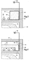
- Fig. 3 shows how a voltage source 68 is connected across the spring 66 by an electrically conducting portion 70 of the magnet, which abuts a contact 72 fixed to the portion of the housing 74 forming the first stop 58. A first end 78 of the spring 66 is thus in electrical engagement with the magnet 56.
- the electrical circuit is completed by a second contact 76 affixed to the second stop 60 which engages a second end 80 of the spring 66.
- magnet could be conducting or other means for applying electrical current to the coil spring could be employed.
- the coil spring through which the current passes must be positioned so as to result in a magnetic field that causes the reeds of the switch to attract, thus closing the reed switch.
Abstract
Description
- The present invention relates to shock sensors incorporating a reed switch in general, and to shock sensors incorporating self-testing in particular.
- A typical automobile manufactured today has a number of active safety systems that function to deploy air bags, and initiate seatbelt retractors and other devices. As the cost of air bags decreases, and the sophistication of air bags increases, the number of air bags provided in each vehicle is increasing. Systems now being installed or under development include multiple air bags to protect the passenger from front, rear, and side impacts, and to position the passenger's body to withstand acceleration. Deployment of safety systems requires sensors that can detect and characterize a crash as it occurs. The widespread use of safety systems results in ever increasing attention to producing systems that can be economically employed on a large number of vehicles.
- Typically, the lowest cost sensors are those formed as micro devices on an integrated circuit chip used to form electronic circuitry. This technology is used to fabricate accelerometers that can detect accelerations indicative of a vehicle crash. These sensors are particularly cost effective when the sensor can be fabricated together with the deployment logic circuitry using the same technology which is used cost effectively for large scale integrated circuit chips. However, the very small size of these devices makes them sensitive to electromagnetic interference and the like, which can result in false indications that a crash is taking place.
- Thus an important role remains for macro scale mechanical devices which are less prone to false readings. Such devices are used to verify the existence of an actual crash event. These macro scale devices employ a sensing mass mounted on a spring or pendulum. Motion of the mass is detected by actuation of a reed switch or a magnetic field sensor.
- The typical reed switch shock sensor employs a magnet, a spring, and a reed switch mounted in a housing. The three components are arranged so that under an acceleration-induced load the magnet acting as an acceleration sensing mass compresses the spring and moves to a position where the magnetic field of the magnet causes the reeds of the reed switch to attract and thus close the reed switch.
- The reed switch shock sensor is a highly reliable component. However, many electronic circuits today incorporate built-in test, and the reed switch is indistinguishable from an open circuit unless the circuit board is undergoing the proper acceleration. Thus, in some cases the shock sensor may incorporate some method of self-testing which can verify the presence of the reed switch and which may cause the reed switch to operate. Such self-testing functions typically require additional parts, including the addition of a self-test electrical coil to cause the reed switch to close.
- What is needed is a shock sensor employing a reed switch that can be self-tested without the addition of a test coil.
- The reed switch based shock sensor of this invention provides means for passing electrical current through the spring used to bias the shock sensing magnetic mass in the unactuated position. The spring extends between a first stop and a shock sensing magnetic mass that is biased against a second stop. So long as the magnetic mass is held against the second stop, the reed switch remains open. A path for electrical current is created which leads through the coil spring used to bias the sensing mass. The coil spring is wrapped around the reed switch, allowing the coil spring to act as an electrical coil. The electric coil generates a magnetic field of sufficient strength to cause the reed switch reeds to attract and so close the reed switch, thus allowing the reed switch to be tested, without the addition of an electrical test coil.
- It is a feature of the present invention to provide a shock sensor that facilitates built-in test.
- It is a further feature of the present invention to provide a shock sensor having a reed switch that can be electrically detected.
- It is another feature of the present invention to provide a shock sensor that can be actuated electronically for a self-test, without the addition of a test coil.
- Further features and advantages of the invention will be apparent from the following detailed description when taken in conjunction with the accompanying drawings.
-
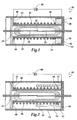
- Fig. 1 is a cross-sectional view of the shock sensor of this invention.
- Fig. 2 is a cross-sectional view of an alternative embodiment of the shock sensor of Fig. 1.
- Fig. 3 in an enlarged detail view of the electrical connection between the housing and the spring of Fig. 1.
- Fig. 4 in an enlarged detail view of the electrical connection between the housing and the spring of Fig. 2.
-
- Referring more particularly to Figs. 1-4 wherein like numbers refer to similar parts, a
shock sensor 20 is shown in Figs 1. Theshock sensor 20 has ahousing 22. Areed switch 24 is mounted on thehousing 22, and ashock sensing magnet 26 is positioned for movement on the housing. Theshock sensing magnet 26 is in the shape of a ring which is positioned coaxially about thereed switch 24. Aspring 32 biases ashock sensing magnet 26 against afirst stop 28 formed byportions 30 of thehousing 22. Thespring 32 extends between themagnet 26 and asecond stop 34 spaced from thefirst stop 28 and spaced axially along thereed switch 24. - When the
shock sensor 20 undergoes acceleration due to a crash event, themagnet 26 compresses thespring 32 until the magnet moves to a second position adjacent the overlappingportions 36 of thereed switch reeds 38. Properly positioned, the magnet will cause the reeds to take on opposite magnetic polarities and so attract to close the switch formed by thereed switch 24. - It is generally not practical or desirable to test a reed switch shock sensor by subjecting it to shock levels simulative of a crash event. It is known in the prior art to place an electrical coil around the reed switch so that when the coil is energized the reed switch closes. It is also known to use an electric coil to cause the
shock sensing magnet 26 to move so as to close thereed switch 24. Such prior art solutions require the addition of an electrical coil, resulting in some increase in cost, size and part count. The shock sensor of thisinvention 20 is arranged to pass a current through thespring 32 which is used to bias the shock sensing magnet against thefirst stop 28. A typical coil used to actuate a reed switch will employ a coil having thousands to tens of thousands of turns, and operation of the reed switch by energizing the coil will typically require a power of a small fraction of one Watt. - Through experimentation it has been shown that coil springs having, for example, between 26 and 33 turns, can support sufficient current to cause actuation of a reed switch in a shock sensor configuration. Table 1 provides test results for two coil springs: part number 251-90-226-00 which has 26 coils and a resistance of 7.3 ohms; and part number 251-90-084-00 which has 27 coils and a resistance of 10.8 ohms. Each coil was positioned about a series of reed switches (Hamlin type MLRR-4) with different ampere turn requirements, as shown in column one of Table 1, the reed switch having ampere turn requirements of 14, 15, 16 and 23 ampere turns.


- Voltage across the coil spring was increased until the switch closed and the voltage at which the switch closed was recorded. The number of ampere turns (Theoretical AT) required was calculated by taking the voltage value at switch pull in, dividing that value by the resistance of the spring to get a value for the current and finally multiplying the value of the current by the number of turns on the spring.
- Similarly, in Table 2, coil spring part No. 251-90-018-00 having 29 coil turns and resistance of 6.9 ohms, and part number 251-90-071-00 having 33 coil turns and resistance of 10.6 ohms were tested with switches having ampere turn requirements between 14 and as high as 29. Again the number of ampere turns (Theoretical AT) required was calculated by taking the voltage value at switch pull in, dividing that value by the resistance of the spring to get a value for the current and finally multiplying the value of the current by the number of turns on the spring.
- Voltage values for switches with higher ampere turn requirements are not entered in the tables where the high voltages caused warping of the springs. Generally, a burning smell was noticed around 5-6 volts when the voltage was left on for around 25 seconds. Therefore it is concluded that reed switches should be used which are sensitive enough to respond to the ampere turns which can be achieved with four volts.
- Looking at the power dissipated, it is evident that 4Volts corresponds to about two Watts of dissipated power. As evidenced by the Theoretical AT becoming substantially greater than the Switch AT at the higher voltages, the resistance of the coil is increasing due to the increased coil temperature. If greater ampere turn values are required in any shock sensor which utilizes the coil spring as a test coil, increasing the number of turns in the coil and/or decreasing the resistance of the coil will be necessary to avoid excessive power dissipation with the attendant undesirable heating of the coil spring.
- Referring to Figs. 1 and 3, it is illustrated how an
electrical voltage source 40 can be connected across thespring 32, which extends between themagnet 26 and a portion of the housing forming asecond stop 34. Referring particularly to Fig. 3, themagnet 26 is shown plated with aconductive material 42 such as copper or silver so that current can readily flow between acontact 44 attached to the portion of thehousing 30 forming thefirst stop 28 and afirst end 46 of thespring 32. Similarly acontact 48 is formed on thesecond stop 34 completing the electrical circuit from theelectrical voltage source 40 to thesecond end 49 of thespring 32. Although movement of themagnet 26 breaks the electrical connection between the spring and thecontact 44, this occurs only during crash induced acceleration. - Referring to Figs. 2 and 4, an alternative
embodiment shock sensor 50 is shown in Fig. 2. Theshock sensor 50 employs areed switch 52 mounted on ahousing 54. Amagnet 56 is movable on the housing and is positioned coaxially about thereed switch 52. Thisshock sensor 50 has the overall configuration of the shock sensor shown in U.S. patent No.5,212,357 to Reneau which is incorporated herein by reference. Thehousing 54 has afirst stop 58 and asecond stop 60 spaced a fixed distance from thefirst stop 58. - The
activation magnet 56, being slidably mounted on thehousing 54, has afirst portion 62 engaged against thefirst stop 58 and asecond portion 64 which engages against the second stop. The magnetfirst portion 62 has a greater magnetic flux than thesecond portion 64. Thereed switch 52 is responsive to the position of theactivation magnet 56 such that the reed switch is activated when the magnet travels to a preselected activation position during movement of the magnet in response to acceleration applied to the sensor. Acoil spring 66 biases themagnet 56 such that thefirst portion 62 engages against thefirst stop 58, and thecoil spring 66 extends between themagnet 56 and thesecond stop 60. - Fig. 3 shows how a
voltage source 68 is connected across thespring 66 by an electrically conductingportion 70 of the magnet, which abuts acontact 72 fixed to the portion of thehousing 74 forming thefirst stop 58. Afirst end 78 of thespring 66 is thus in electrical engagement with themagnet 56. The electrical circuit is completed by asecond contact 76 affixed to thesecond stop 60 which engages asecond end 80 of thespring 66. - It should be understood that the magnet could be conducting or other means for applying electrical current to the coil spring could be employed.
- It should be understood that the coil spring through which the current passes must be positioned so as to result in a magnetic field that causes the reeds of the switch to attract, thus closing the reed switch.
- It should be understood that the number of ampere turns required to activate a given reed switch is dependent on the detail configuration of the coil, and so the rated ampere turns is to some extent a relative measurement.
- It is understood that the invention is not limited to the particular construction and arrangement of parts herein illustrated and described, but embraces such modified forms thereof as come within the scope of the following claims.
Claims (12)
- A shock sensor of the type comprising:wherein the improvement comprises: a voltage source connected across the first end, and the second end of the coil spring, so as to cause a current to flow therethrough which is sufficient to cause the reed switch to close.a housing having a first stop and a second stop spaced from the first stop;a shock sensing magnetic mass slidably mounted on the housing and having a first portion engaged against the first stop when the housing is not undergoing acceleration;a reed switch mounted to the housing to be responsive to the position of the shock sensing magnetic mass such that the reed switch is activated when the shock sensing magnetic mass travels to an activation position during movement of the shock sensing magnetic mass in response to an acceleration force applied to the sensor;a coil spring extending between a first end which is engaged with the shock sensing mass, and a second end which is engaged with the second stop, the coil spring wrapped coaxially about the reed switch, the spring biasing the shock sensing magnetic mass by extending between the second stop and the shock sensing magnetic mass biasing the activation magnet against the first stop, a preselected level of acceleration causing the magnet to slide on the housing to activate the reed switch;
- The shock sensor of claim 1 wherein the voltage source supplies a voltage of less than about four volts.
- The shock sensor of claim 1 further comprising:a first electrical connection mounted to the housing and positioned on the first stop;a second electrical connection mounted on the housing and positioned on the second stop, wherein the second end of the coil spring is engaged with the second electrical connection, and wherein the shock sensing magnetic mass forms an electrical connection between the first electrical connection and the first end of the coil spring.
- The shock sensor of claim 3 wherein a portion of the shock sensing magnetic mass is covered with a conductive material which extends between the first stop and the first end of the coil spring.
- A shock sensor comprising:a housing having a first stop and a second stop;an activation magnet mounted for movement on the housing between the second stop and the first stop;a reed switch mounted to the housing and coaxial with the activation magnet such that the reed switch is activated when the magnet travels to an activation position in response to an acceleration force applied to the sensor;a coil spring wrapped coaxially about the reed switch, the spring biasing the magnet such that the spring extends between the first stop and the activation magnet to bias the activation magnet against the second stop, so that the reed switch remains unactivated until the housing is subjected to the acceleration force, the acceleration causing the magnet to slide on the housing to the activation position to activate the reed switch;a first electrical connection mounted to the housing and positioned on the first stop; anda second electrical connection mounted on the housing and positioned on the second stop, wherein the coil spring is engaged with the second electrical connection, and wherein the shock sensing magnetic mass forms an electrical connection between the first electrical connection and the coil spring.
- The shock sensor of claim 1 wherein a voltage is connected between the first electrical connection and the second electrical connection.
- The shock sensor of claim 6 wherein the voltage source supplies a voltage of less than about four volts.
- The shock sensor of claim 6 wherein a portion of the shock sensing magnetic mass is covered with a conductive material which extends between the first stop and the first end of the coil spring.
- A shock sensor comprising:a housing;a shock sensing magnet mass slidably mounted on the housing;a reed switch mounted to the housing to be responsive to the position of the shock sensing magnetic mass;a coil spring extending between the shock sensing magnetic mass and the housing and forming a coil about the reed switch;a voltage source connected across the coil spring, so as to cause a current to flow therethrough which is sufficient to cause the reed switch to close.
- The shock sensor of claim 9 wherein the voltage source supplies a voltage of less than about four volts.
- The shock sensor of claim 9 further comprising:a first electrical connection mounted to the housing and positioned on a first stop;a second electrical connection mounted on the housing and positioned on a second stop, wherein the coil spring is engaged with the second electrical connection, and wherein the shock sensing magnetic mass forms an electrical connection between the first electrical connection and the coil spring, and the voltage source is connected to the first electrical connection and the second electrical connection.
- The shock sensor of claim 11 wherein a portion of the shock sensing magnetic mass is covered with a conductive material which extends between the first stop and the coil spring.
Applications Claiming Priority (2)
| Application Number | Priority Date | Filing Date | Title |
|---|---|---|---|
| US860908 | 2001-05-18 | ||
| US09/860,908 US6335498B1 (en) | 2001-05-18 | 2001-05-18 | Shock sensor employing a spring coil for self-test |
Publications (2)
| Publication Number | Publication Date |
|---|---|
| EP1258896A2 true EP1258896A2 (en) | 2002-11-20 |
| EP1258896A3 EP1258896A3 (en) | 2004-04-28 |
Family
ID=25334335
Family Applications (1)
| Application Number | Title | Priority Date | Filing Date |
|---|---|---|---|
| EP02009372A Withdrawn EP1258896A3 (en) | 2001-05-18 | 2002-05-06 | Shock sensor employing a coil spring for self-test |
Country Status (2)
| Country | Link |
|---|---|
| US (1) | US6335498B1 (en) |
| EP (1) | EP1258896A3 (en) |
Families Citing this family (3)
| Publication number | Priority date | Publication date | Assignee | Title |
|---|---|---|---|---|
| KR100616508B1 (en) * | 2002-04-11 | 2006-08-29 | 삼성전기주식회사 | Film bulk acoustic resonator and method for fabrication thereof |
| US7170019B2 (en) * | 2003-07-14 | 2007-01-30 | Cheerine Development (Hong Kong), Ltd. | Inertia switch and flashing light system |
| US7541939B2 (en) | 2007-03-15 | 2009-06-02 | Apple Inc. | Mounted shock sensor |
Citations (4)
| Publication number | Priority date | Publication date | Assignee | Title |
|---|---|---|---|---|
| US4980526A (en) * | 1989-04-06 | 1990-12-25 | Hamlin Incorporated | Device and method for testing acceleration shock sensors |
| US4987276A (en) * | 1988-09-09 | 1991-01-22 | Audi Ag | Deceleration switch |
| US5416293A (en) * | 1994-08-17 | 1995-05-16 | Hamlin, Inc. | Shock sensor including a compound housing and magnetically operated reed switch |
| US6142007A (en) * | 1997-06-11 | 2000-11-07 | Nippon Aleph Corporation | Shock sensor |
Family Cites Families (4)
| Publication number | Priority date | Publication date | Assignee | Title |
|---|---|---|---|---|
| US5212357A (en) * | 1991-08-14 | 1993-05-18 | Hamlin, Inc. | Extended minimum dwell shock sensor |
| EP0545393B1 (en) * | 1991-12-02 | 1997-03-12 | Tokin Corporation | Shock sensor |
| DE4400206A1 (en) * | 1993-01-08 | 1994-07-28 | Nippon Aleph | Shock detection device |
| US5770792A (en) * | 1995-10-27 | 1998-06-23 | Nippon Aleph Corporation | Shock sensors |
-
2001
- 2001-05-18 US US09/860,908 patent/US6335498B1/en not_active Expired - Fee Related
-
2002
- 2002-05-06 EP EP02009372A patent/EP1258896A3/en not_active Withdrawn
Patent Citations (4)
| Publication number | Priority date | Publication date | Assignee | Title |
|---|---|---|---|---|
| US4987276A (en) * | 1988-09-09 | 1991-01-22 | Audi Ag | Deceleration switch |
| US4980526A (en) * | 1989-04-06 | 1990-12-25 | Hamlin Incorporated | Device and method for testing acceleration shock sensors |
| US5416293A (en) * | 1994-08-17 | 1995-05-16 | Hamlin, Inc. | Shock sensor including a compound housing and magnetically operated reed switch |
| US6142007A (en) * | 1997-06-11 | 2000-11-07 | Nippon Aleph Corporation | Shock sensor |
Also Published As
| Publication number | Publication date |
|---|---|
| US6335498B1 (en) | 2002-01-01 |
| EP1258896A3 (en) | 2004-04-28 |
Similar Documents
| Publication | Publication Date | Title |
|---|---|---|
| US4980526A (en) | Device and method for testing acceleration shock sensors | |
| US7081692B2 (en) | Airbag deployment monitor and sensing electronics | |
| US7116220B2 (en) | Seat belt latch sensor assembly | |
| JPH07285415A (en) | Shock sensor for vehicle safety system | |
| US5416293A (en) | Shock sensor including a compound housing and magnetically operated reed switch | |
| EP2541259A1 (en) | Sensors for detecting rapid deceleration/acceleration events | |
| US6184764B1 (en) | Pendulum mass acceleration sensor | |
| US6335498B1 (en) | Shock sensor employing a spring coil for self-test | |
| US5212357A (en) | Extended minimum dwell shock sensor | |
| US3943390A (en) | Deceleration detecting device | |
| WO1997025624A2 (en) | Mechanical shock sensor | |
| US5032696A (en) | Crash sensor switch | |
| KR100372276B1 (en) | Method for diagnosing safety sensor for airbag | |
| US5196660A (en) | Acceleration sensor | |
| US6429392B1 (en) | Magnetic bi-directional shock sensor | |
| JPH0795077B2 (en) | Shock sensor with magnetically actuated reed switch | |
| KR200358261Y1 (en) | Sensing device for putting on safety belt | |
| JP2002048814A (en) | Shock sensor | |
| JP3024190U (en) | Collision sensor circuit for operating vehicle occupant protection device | |
| Behr | A magnetically damped crash sensor providing testability and dynamic system reconfiguration | |
| JP2001351489A (en) | Proximity switch for position detection | |
| JP2004135776A (en) | Buckle device | |
| JPH04254762A (en) | Collision detector | |
| JP2001324514A (en) | Impact sensor | |
| JPH06302255A (en) | Impact sensor |
Legal Events
| Date | Code | Title | Description |
|---|---|---|---|
| PUAI | Public reference made under article 153(3) epc to a published international application that has entered the european phase |
Free format text: ORIGINAL CODE: 0009012 |
|
| 17P | Request for examination filed |
Effective date: 20020521 |
|
| AK | Designated contracting states |
Kind code of ref document: A2 Designated state(s): AT BE CH CY DE DK ES FI FR GB GR IE IT LI LU MC NL PT SE TR |
|
| AX | Request for extension of the european patent |
Free format text: AL;LT;LV;MK;RO;SI |
|
| PUAL | Search report despatched |
Free format text: ORIGINAL CODE: 0009013 |
|
| AK | Designated contracting states |
Kind code of ref document: A3 Designated state(s): AT BE CH CY DE DK ES FI FR GB GR IE IT LI LU MC NL PT SE TR |
|
| AX | Request for extension of the european patent |
Extension state: AL LT LV MK RO SI |
|
| RAP1 | Party data changed (applicant data changed or rights of an application transferred) |
Owner name: KEY SAFETY SYSTEMS, INC. |
|
| AKX | Designation fees paid |
Designated state(s): DE FR GB IT |
|
| STAA | Information on the status of an ep patent application or granted ep patent |
Free format text: STATUS: THE APPLICATION HAS BEEN WITHDRAWN |
|
| 18W | Application withdrawn |
Effective date: 20070618 |