EP1258756A2 - Photonic switch - Google Patents
Photonic switch Download PDFInfo
- Publication number
- EP1258756A2 EP1258756A2 EP02253197A EP02253197A EP1258756A2 EP 1258756 A2 EP1258756 A2 EP 1258756A2 EP 02253197 A EP02253197 A EP 02253197A EP 02253197 A EP02253197 A EP 02253197A EP 1258756 A2 EP1258756 A2 EP 1258756A2
- Authority
- EP
- European Patent Office
- Prior art keywords
- photonic switch
- input
- output
- type
- switch
- Prior art date
- Legal status (The legal status is an assumption and is not a legal conclusion. Google has not performed a legal analysis and makes no representation as to the accuracy of the status listed.)
- Ceased
Links
Images




Classifications
-
- H—ELECTRICITY
- H04—ELECTRIC COMMUNICATION TECHNIQUE
- H04Q—SELECTING
- H04Q11/00—Selecting arrangements for multiplex systems
- H04Q11/0001—Selecting arrangements for multiplex systems using optical switching
- H04Q11/0062—Network aspects
-
- G—PHYSICS
- G02—OPTICS
- G02B—OPTICAL ELEMENTS, SYSTEMS OR APPARATUS
- G02B6/00—Light guides; Structural details of arrangements comprising light guides and other optical elements, e.g. couplings
- G02B6/24—Coupling light guides
- G02B6/26—Optical coupling means
- G02B6/35—Optical coupling means having switching means
- G02B6/354—Switching arrangements, i.e. number of input/output ports and interconnection types
- G02B6/356—Switching arrangements, i.e. number of input/output ports and interconnection types in an optical cross-connect device, e.g. routing and switching aspects of interconnecting different paths propagating different wavelengths to (re)configure the various input and output links
-
- G—PHYSICS
- G02—OPTICS
- G02B—OPTICAL ELEMENTS, SYSTEMS OR APPARATUS
- G02B6/00—Light guides; Structural details of arrangements comprising light guides and other optical elements, e.g. couplings
- G02B6/24—Coupling light guides
- G02B6/26—Optical coupling means
- G02B6/35—Optical coupling means having switching means
- G02B6/354—Switching arrangements, i.e. number of input/output ports and interconnection types
- G02B6/3562—Switch of the bypass type, i.e. enabling a change of path in a network, e.g. to bypass a failed element in the network
-
- H—ELECTRICITY
- H04—ELECTRIC COMMUNICATION TECHNIQUE
- H04Q—SELECTING
- H04Q11/00—Selecting arrangements for multiplex systems
- H04Q11/0001—Selecting arrangements for multiplex systems using optical switching
- H04Q11/0005—Switch and router aspects
- H04Q2011/0007—Construction
- H04Q2011/0015—Construction using splitting combining
-
- H—ELECTRICITY
- H04—ELECTRIC COMMUNICATION TECHNIQUE
- H04Q—SELECTING
- H04Q11/00—Selecting arrangements for multiplex systems
- H04Q11/0001—Selecting arrangements for multiplex systems using optical switching
- H04Q11/0005—Switch and router aspects
- H04Q2011/0007—Construction
- H04Q2011/0024—Construction using space switching
-
- H—ELECTRICITY
- H04—ELECTRIC COMMUNICATION TECHNIQUE
- H04Q—SELECTING
- H04Q11/00—Selecting arrangements for multiplex systems
- H04Q11/0001—Selecting arrangements for multiplex systems using optical switching
- H04Q11/0005—Switch and router aspects
- H04Q2011/0037—Operation
- H04Q2011/0043—Fault tolerance
-
- H—ELECTRICITY
- H04—ELECTRIC COMMUNICATION TECHNIQUE
- H04Q—SELECTING
- H04Q11/00—Selecting arrangements for multiplex systems
- H04Q11/0001—Selecting arrangements for multiplex systems using optical switching
- H04Q11/0062—Network aspects
- H04Q2011/0079—Operation or maintenance aspects
- H04Q2011/0081—Fault tolerance; Redundancy; Recovery; Reconfigurability
-
- H—ELECTRICITY
- H04—ELECTRIC COMMUNICATION TECHNIQUE
- H04Q—SELECTING
- H04Q11/00—Selecting arrangements for multiplex systems
- H04Q11/0001—Selecting arrangements for multiplex systems using optical switching
- H04Q11/0062—Network aspects
- H04Q2011/0079—Operation or maintenance aspects
- H04Q2011/0083—Testing; Monitoring
Definitions
- This invention relates to photonic switch systems.
- Optical fiber offers a solution to the difficulties affecting conventional electrical interconnections. For example, optical fiber is less susceptible to inductive or capacitive coupling effects than are electrical interconnections. Optical fiber also offers increased bandwidth and substantial avoidance of electromagnetic interference. The advantages of optical fiber become more important as the transmission rates increase.
- Many communications networks feature hybrid, optical-electrical semiconductor circuits that employ photodetectors, electrical switches, optical modulators and/or lasers.
- an alternative approach uses a photonic switch system, which performs switching operations of light pulses or photons (referred to generally as "light signals") without the need for converting and re-converting signals between the optical domain to the electrical domain.
- a photonic switch system comprising a first photonic switch having a plurality of inputs and outputs, a second photonic switch having a plurality of inputs and outputs, a plurality of head-end modules each having an input port for receiving incoming light signals, a first output port and a second output port, the first output port being connectable to a respective input of the first photonic switch and the second output port being connectable to a respective input of the second photonic switch, a plurality of tail-end modules each having an output port for transmitting outgoing light signals, a first input port and a second input port, the first input port being connectable to a respective output of the first photonic switch and the second output port being connectable to a respective output of the second photonic switch.
- a method of performing a bridge and roll operation on incoming optical signals in a photonic switch system having a first photonic switch connected such that an optical path is established only though the first photonic switch, and having a plurality of head-end and tail-end modules and a second photonic switch comprising the steps of: connecting a second output port of each module of the plurality of head-end modules to a respective input of the second photonic switch and connecting a second input port of each of the plurality of the tail-end modules to a respective output of the second photonic switch; re-configuring the head-end modules and the tail-end modules so that the incoming light signals that are received on the input ports of the head-end modules are re-routed through the second photonic switch to the output ports of the tail-end modules; and disconnecting a first output port of each head-end module from the first photonic switch and disconnecting a first input port of each tail-end module from the first photonic switch.
- the bridge and roll method facilitates protection, maintenance, repair and upgrade of the primary photonic switch.
- the bridge and roll method may be reversed in order to restore the original inputs and outputs on the primary photonic switch after protection, maintenance, repair or upgrade has been performed.
- the present invention also provides a method for consolidating multiple wavelengths or multiple bands of wavelengths into single fibers.
- a photonic switch system 100 comprising a plurality of photonic switches shown for convenience as a primary photonic switch 102 having a plurality of inputs 102A , 102B and a plurality of outputs 102C , 102D , and a secondary photonic switch 104 having a plurality of inputs 104A , 104B and a plurality of outputs 104C,104D.
- the primary photonic switch 102 is configured to selectively connect any of its inputs to any of its outputs in known fashion and the secondary photonic switch 104 is similarly configured to connect corresponding inputs to corresponding outputs.
- the photonic switch system 100 also comprises a plurality of head-end modules 106 each having an input port 106A , a first output port 106B and a second output port 106C , and a plurality of tail-end modules 108 each having an output port 108A , a first input port 108B and a second input port 108C .
- the first output port 106B of each head-end module 106 is connected 114 to a respective input 102A,102B of the primary photonic switch 102 and the first input port 108B of each tail-end module 108 is connected 116 to a respective output 102C,102D of the primary photonic switch 102.
- the number of inputs on the primary photonic switch 102 and the secondary photonic switch 104 may be greater than the number of head-end modules 106 .
- the number of outputs on the primary photonic switch 102 and the secondary photonic switch 104 may be greater than the number of tail-end modules 108 .
- the input port 106A of each head-end module 106 is connectable to a respective input optical fiber 110.
- the output port 108A of each tail-end module 108 is connectable to a respective output optical fiber 112 .
- the photonic switch system 100 of Figure 1 is shown configured with a primary photonic switch 102 and a secondary photonic switch 104 , it should be understood that the photonic switch system 100 may be configured having one or more primary photonic switches and having one or more secondary photonic switches (that is, an M:N system with M primary photonic switches and N secondary photonic switches where M and N are whole numbers) and still be within the scope of this invention. Furthermore, the photonic switch system 100 may be configured wherein the primary photonic switch 102 and secondary photonic switch 104 are integrated into a single unit. That is, a subset of a single photonic switch (not shown) functions as the primary photonic switch 102 and another subset of the single photonic switch functions as the secondary photonic switch 104 .
- any one of the head-end modules 106 may comprise, for example, a 1:2 splitter 202 having an input 202A , a first output 202B and a second output 202C .
- the input 202A of the 1:2 splitter 202 is connected to the input port 106A of the head-end module 106 .
- the first output 202B of the 1:2 splitter 202 is connected to the- first output port 106B of the head-end module 106.
- the second output 202C of the 1:2 splitter 202 is connected to the second output port 106C of the head-end module 106.
- any one of the head-end modules 106 may comprise a 1x2 switch 204 having and an input 204A , a first output 204B and a second output 204C.
- the input 204A of the 1x2 switch 204 is connected to the input port 106A of the head-end module 106 .
- the first output 204B of the 1x2 switch 204 is connected to the first output port 106B of the head-end module 106.
- the second output 204C of the 1x2 switch 204 is connected to the second output port 106C of the head-end module 106 .
- any one of the head-end modules 106 may comprise a 1:2 splitter 206 having an input 206A , a first output 206B and a second output 206C , a first variable optical attenuator (VOA) 208 and a second VOA 210 - each VOA 208,210 having an input 208A,210A and an output 208B,210B .
- the input 206A of the 1:2 splitter 206 is connected to the input port 106A of the head-end module 106 .
- the first output 206B of the 1:2 splitter 206 is connected the input 208A of the first VOA 208 .
- the output 208B of the first VOA 208 is connected to the first output port 106B of the head-end module 106.
- the second output 206C of the 1:2 splitter 206 is connected to the input 210A of the second VOA 210.
- the output 210B of the second VOA 210 is connected to the second output port 106C of the head-end module 106.
- any one of the head-end modules 106 may comprise a 1:2 splitter 212 having an input 212A, a first output 212B and a second output 212C , a first shutter 214 and a second shutter 216 - each shutter 214,216 having an input 214A,216A and an output 214B,216B.
- the topology of this alternative embodiment is the same as the embodiment of Figure 2C except that each VOA 208,210 is replaced with a shutter 214,216.
- any one of the head-end modules 106 may comprise a 1x2 switch 218 having an input 218A , a first output 218B and a second output 218C , a first VOA 220 and a second VOA 222 - each VOA 220,222 having an input 220A,222A and an output 220B,222B .
- the topology of this alternative embodiment is the same as the embodiment of Figure 2C except that the splitter 206 is replaced with the 1x2 switch 218.
- any one of the tail-end modules 108 may comprise a 2:1 combiner 302 having an output 302A , a first input 302B and a second input 302C .
- the output of the 2:1 combiner 302 is connected to the output port 108A of the tail-end module 108 .
- the first input 302B of the 2:1 combiner 302 is connected to the first input port 108B of the tail-end module 108 .
- the second output 302C of the 2:1 combiner 302 is connected to the second input port 108C of the tail-end module 108 .
- any one of the tail-end modules 108 may comprise a 2x1 switch 304 having an output 304A , a first input 304B and a second input 304C .
- the topology of this alternative embodiment is the same as the embodiment of Figure 3A except that the combiner 302 is replaced with the 2x1 switch 304.
- any one of the tail-end modules 108 may comprise, for example, a 2:1 combiner 306 having an output 306A , a first input 306B and a second input 306C, a first VOA 308 and a second VOA 310 - each VOA 308,310 having an input 308A,310A and an output 308B,310B .
- the output 306A of the 2:1 combiner 306 is connected to the output port 108A of the tail-end module 108 .
- the first input 306B of the 2:1 combiner 306 is connected to the output 308B of the first VOA 308.
- the input 308A of the first VOA 308 is connected to the first input port 108B of the tail-end module 108.
- the second input 306C of the 2:1 combiner 306 is connected to the output 310B of the second VOA 310.
- the input 310A of the second VOA 310 is connected to the second input port 108C of the tail-end module 108.
- any one of the tail-end modules 108 may comprise a 2:1 combiner 312 having an output 312A , a first input 312B and a second input 312C, a first shutter 314 and a second shutter 316 - each shutter 314,316 having an input 314A,316A and an output 314B,316B.
- the topology of this alternative embodiment is the same as the embodiment of Figure 3C except that each VOA 308,310 is replaced with a shutter 314,316 .
- any one of the tail-end modules 108 may comprise a 2x1 switch 318 having an output 318A, a first input 318B and a second input 318C, a first VOA 320 and a second VOA 322 - each VOA 320,322 having an input 320A,322A and an output 320B,322B.
- the topology of this alternative embodiment is the same as the embodiment of Figure 3C except that the combiner 306 is replaced with the 2x1 switch 318.
- any one of the tail-end modules 108 may comprise, for example, a 2x2 switch 324 having a first input 324A, a second input 324B, a first output 324C and a second output 324D, and a performance monitor 326 having an input 326A.
- the first input 324A of the 2x2 switch 324 is connected to the first input port 108B of the tail-end module 108.
- the second input 324B of the 2x2 switch 324 is connected to the second input port 108C of the tail-end module 108 .
- the first output 324C of the 2x2 switch 324 is connected to the input 326A of the performance monitor 326 .
- the second output 324D of the 2x2 switch 324 is connected to the output port 108A of the tail-end module 108 .
- head-end modules 106 and tail-end modules 108 are: the head-end module of Figure 2A and the tail-end module of Figure 3B ; the head-end module of Figure 2A and the tail-end module of Figure 3C ; the head-end module of Figure 2A and the tail-end module of Figure 3D ; the head-end module of Figure 2B and the tail-end module of Figure 3A ; the head-end module of Figure 2B and the tail-end module of Figure 3B ; the head-end module of Figure 2C and the tail-end module of Figure 3A ; the head-end module of Figure 2D and the tail-end module of Figure 3A ; the head-end module of Figure 2C and the tail-end module of Figure 3B ; the head-end module of Figure 2D and the tail-end module of Figure 3B ; the head-end module of Figure 2D and the tail-end module of Figure 3B ; the head-end module of Figure 2E and the tail-end module of Figure 3A ; the head-end module
- the input optical fibers 110 carry light signals that may be, for example, single wavelengths, a band of different wavelengths or a plurality of bands of different wavelengths or any combination thereof.
- the light signals on the input optical fibers 110 are routed to the output optical fibers 112 via a primary optical path 122.
- the primary optical path 122 is from the input ports 106A of the head-end modules 106 , through the first output ports 106B of the head-end modules 106 , through the connections 114 , through the primary photonic switch 102 , through the connections 116 , through the first input ports 108B of the tail-end modules 108 to the output ports 108A of the tail-end modules 108 .
- the paths of the light signals through the head-end modules 106 and the tail-end modules 108 are indicated by dotted lines on each module.
- the second output ports 106C of the head-end modules 106 are connected 118 to respective inputs 104A,104B of the secondary photonic switch 104 .
- the second input ports 108C of the tail-end modules 108 are connected 120 to respective outputs 104C,104D of the secondary photonic switch 104 (Step 702).
- This step 702 is known as bridging.
- the head-end modules 106 are re-configured so that the light signals on the input optical fibers 110 are re-routed from the primary optical path 122 to a secondary optical path 124 (Step 704 ).
- This step 704 is known as rolling. It is preferably executed in a time frame that causes only a small (less than 50 ms) interruption to the light signals.
- the secondary optical path 124 is from the input ports 106A of the head-end modules 106 , through the second output ports 106C of the head-end modules 106 , through the connections 118 , through the secondary photonic switch 104 , through the connections 120 , through the second input ports 108C of the tail-end modules 108 to the output ports 108A of the tail-end modules 108 .
- connections 118,120 made in the bridging step 702 may be made at any time before the subsequent rolling step 704 such as during the manufacture of the photonic switch system 100 or after installation of the photonic switch system 100 on a customer's premises.
- the step 704 of rolling is accomplished by re-configuring the 2x1 switch 304 so that the light signals at the output 304A of the 2x1 switch 304 are derived from the light signals at the second input 304C instead of the first input 304B .
- both photonic switches 102,104 receive incoming signals which is useful for monitoring performance of the photonic switches 102,104 .
- the step 704 of rolling is accomplished by re-configuring the first VOA 308 and the second VOA 310 so that the first VOA 308 has substantially higher attenuation than the second VOA 310 instead of the second VOA 310 having substantially higher attenuation than the first VOA 308.
- the VOAs 308,310 also enable nodal output level compensation.
- the step 704 of rolling is accomplished by re-configuring the first shutter 314 and the second shutter 316 so that the first shutter 314 transmits substantially no light signals from the input 314A of the first shutter 314 to the output 314B of the first shutter 314 and the second shutter 316 transmits substantially all of the light signals from the input 316A of the second shutter 316 to the output 316B of the second shutter instead of the first shutter 314 transmitting substantially all of the light signals from the input 314A of the first shutter 314 to the output 314B of the first shutter 314 and the second shutter 316 transmitting substantially none of the light signals from the input 316A of the second shutter 316 to the output 316B of the second shutter.
- the shutters 314,316 are less expensive than the VOAs 308,310 of the previous embodiment and have lower loss and higher reliability.
- the step 704 of rolling is accomplished by re-configuring the 1x2 switch 204 so that the light signals at the input 204A of the 1x2 switch 204 are routed to the second output 204C instead of the first input 204B .
- This embodiment has the advantage over the previous three embodiments in that it may reduce back-reflections from a fixed termination.
- the step 704 of rolling is accomplished by re-configuring the 1x2 switch 204 so that the light signals at the input 204A of the 1x2 switch 204 are routed to the second output 204C instead of the first input 204B and re-configuring the 2x1 switch 304 so that the light signals at the output 304A of the 2x1 switch 304 are derived from the light signals at the second input 304C instead of the first input 304B .
- This embodiment has the lowest transmission loss since switches can have lower loss than splitters and combiners. However this combination may be less reliable, and it requires head-end and tail-end switch coordination.
- the step 704 of rolling is accomplished by re-configuring the first VOA 208 and the second VOA 210 so that the first VOA 208 has substantially higher attenuation than the second VOA 210 instead of the second VOA 210 having substantially higher attenuation than the first VOA 208.
- This embodiment is opposite to the embodiment where the combination of the head-end module of Figure 2A and the tail-end module of Figure 3C is used. However this embodiment reduces back-reflections from a fixed termination, it also enables nodal input level compensation.
- the step 704 of rolling is accomplished by re-configuring the first shutter 214 and the second shutter 216 so that the first shutter 214 transmits substantially no light signals from the input 214A of the first shutter 214 to the output 214B of the first shutter 214 and the second shutter 216 transmits substantially all of the light signals from the input 216A of the second shutter 216 to the output 216B of the second shutter instead of the first shutter 214 transmitting substantially all of the light signals from the input 214A of the first shutter 214 to the output 214B of the first shutter 214 and the second shutter 216 transmitting substantially none of the light signals from the input 216A of the second shutter 216 to the output 216B of the second shutter.
- This embodiment is opposite to the embodiment where the combination of the head-end module of Figure 2A and the tail-end module of Figure 3D is used, however this embodiment reduces back-reflections from a fixed termination.
- the step 704 of rolling is accomplished by re-configuring the first VOA 208 and the second VOA 210 so that the first VOA 208 has substantially higher attenuation than the second VOA 210 instead of the second VOA 210 having substantially higher attenuation than the first VOA 208 and re-configuring the 2x1 switch 304 so that the light signals at the output 304A of the 2x1 switch 304 are derived from the light signals at the second input 304C instead of the first input 304B .
- This embodiment is opposite to the embodiment where the combination of the head-end module of Figure 2B and the tail-end module of Figure 3C is used, however it enables nodal input rather than nodal output level compensation.
- combinations with active head-end and tail-end modules may have less loss but be more unreliable and require coordination.
- the step 704 of rolling is accomplished by re-configuring the first shutter 214 and the second shutter 216 so that the first shutter 214 transmits substantially no light signals from the input 214A of the first shutter 214 to the output 214B of the first shutter 214 and the second shutter 216 transmits substantially all of the light signals from the input 216A of the second shutter 216 to the output 216B of the second shutter instead of the first shutter 214 transmitting substantially all of the light signals from the input 214A of the first shutter 214 to the output 214B of the first shutter 214 and the second shutter 216 transmitting substantially none of the light signals from the input 216A of the second shutter 216 to the output 216B of the second shutter; and re-configuring the 2x1 switch 304 so that the light signals at the output 304A of the 2x1 switch 304 are derived from the light signals at the second input 304C instead of the first input
- the step 704 of rolling is accomplished by re-configuring the 1x2 switch 204 so that the light signals at the input 204A of the 1x2 switch 204 are routed to the second output 204C instead of the first input 204B and re-configuring the first VOA 308 and the second VOA 310 so that the first VOA 308 has substantially higher attenuation than the second VOA 310 instead of the second VOA 310 having substantially higher attenuation than the first VOA 308 .
- this embodiment with an active head-end and tail-end has lower transmission loss but also lower reliability, and requires coordination.
- the step 704 of rolling is accomplished by re-configuring the 1x2 switch 204 so that the light signals at the input 204A of the 1x2 switch 204 are routed to the second output 204C instead of the first input 204B and re-configuring the first VOA 220 and the second VOA 222 so that the first VOA 220 has substantially higher attenuation than the second VOA 222 instead of the second VOA 222 having substantially higher attenuation than the first VOA 220 .
- This embodiment is similar to the embodiment where the combination of the head-end module of Figure 2C and the tail-end module of Figure 3A is used, however this embodiment has lower transmission loss but lower reliability.
- the step 704 of rolling is accomplished by re-configuring the 2x2 switch 324 so that the light signals at the first input 324A are transmitted to the second output 324D and the light signals at the second input 324B are transmitted to the first output 324C instead of the light signals at the first input 324A being transmitted to the first output 324C and the light signals at the second input 324B being transmitted to the second output 324D.
- This embodiment enables the monitoring of one of the photonic switches 102 , 104 .
- the step 704 of rolling is accomplished by re-configuring the 1x2 switch 204 so that the light signals at the input 204A of the 1x2 switch 204 are routed to the second output 204C instead of the first input 204B and re-configuring the first shutter 314 and the second shutter 316 so that the first shutter 314 transmits substantially no light signals from the input 314A of the first shutter 314 to the output 314B of the first shutter 314 and the second shutter 316 transmits substantially all of the light signals from the input 316A of the second shutter 316 to the output 316B of the second shutter instead of the first shutter 314 transmitting substantially all of the light signals from the input 314A of the first shutter 314 to the output 314B of the first shutter 314 and the second shutter 316 transmitting substantially none of the light signals from the input 316A of the second shutter 316 to the output 316B of the second shutter.
- the step 704 of rolling is accomplished by re-configuring the first VOA 208 and the second VOA 210 so that the first VOA 208 has substantially higher attenuation than the second VOA 210 instead of the second VOA 210 having substantially higher attenuation than the first VOA 208 and re-configuring the first VOA 308 and the second VOA 310 so that the first VOA 308 has substantially higher attenuation than the second VOA 310 instead of the second VOA 310 having substantially higher attenuation than the first VOA 308.
- This combination has the disadvantage of lower reliability, duplicated level control and required coordination.
- the first output ports 106B of the head-end modules 106 are left in place or disconnected from the inputs 102A,102B of the primary photonic switch 102.
- the first input ports 108B of the tail-end modules 108 are left in place or disconnected from the outputs 102C, 102D of the primary photonic switch 102 (Step 706 ).
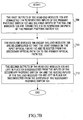
- bridge and roll technique described above can be executed in reverse as described with reference to Figures 1 , 4 , 5 , 6 and the flowchart of Figure 7B .
- the first output ports 106B of the head-end modules 106 are already in place or connected 114 to respective inputs 102A,102B of the primary photonic switch 102.
- the first input ports 108B of the tail-end modules 108 are already in place or connected to 116 respective outputs 102C , 102D of the primary photonic switch 102 (Step 708 ).
- the head-end modules 106 are re-configured so that the light signals on the input optical fibers 110 are re-routed from the secondary optical path 124 to the primary optical path 122 . (Step 710 ).
- the second output ports 106C of the head-end modules 106 are left in place or disconnected from inputs 104A,104B of the secondary photonic switch 104 and the second input ports 108C of the tail-end modules 108 are left in place or disconnected from the outputs 104C , 104D of the secondary photonic switch 104 (Step 712 ).
- the photonic switch system 800 of Figure 8 is identical to the photonic switch system 100 of Figure 1 except that a multiplexor 802 has been added.
- the multiplexor 802 has an output 802A and a plurality of inputs 802B , 802C where the output 802A is connected 804 to an input 104A of the secondary photonic switch 104 .
- the second output ports 106C of the head-end modules 106 are connected 906 to respective inputs 802B,802C of the multiplexor 802 . All of the second output ports 106C are shown connected to inputs 802B , 802C of the multiplexor 802 for convenience, however only a subset of the second output ports 106C may be connected to inputs 802B , 802C of the multiplexor 802 and still fall within the scope of the invention.
- the second input ports 108C of the tail-end modules 108 are connected 120 to respective outputs 104C,104D of the secondary photonic switch 104 (Step 1202).
- the head-end modules 106 are re-configured so that the light signals on the input optical fibers 110 are re-routed from the primary optical path 122 to the secondary optical path 124 through to photonic switch 104 (Step 1204 ).
- connections 906 , 120 made in the bridging step 1202 may be made at any time before the subsequent rolling step 1204 such as during the manufacture of the photonic switch system 800 or after installation of the photonic switch system 800 on a customer's premises. It should also be appreciated the connections 906 , 120 may be made manually or automatically under remote control.
- photonic switch 104 is configured such that the input 104A to which the output 802A of the multiplexer is connected may be selectively connected to any of the outputs 104C, 104D of photonic switch 104.
- the first output ports 106B of the head-end modules 106 are left in place or disconnected from the inputs 102A,102B of the primary photonic switch 102 .
- the first input ports 108B of the tail-end modules 108 are left in place or disconnected from the outputs 102C , 102D of the primary photonic switch 102 (Step 1206).
- a photonic switch system 1300 comprising a plurality of photonic switches shown for convenience as a primary photonic switch 102 having a plurality of inputs 102A,102B and a plurality of outputs 102C,102D, and a secondary photonic switch 104 having a plurality of inputs 104A , 104B and a plurality of outputs 104C , 104D .
- the photonic switch system 1300 also comprises: a plurality of head-end 2x2 switches 1306 each having a first input 1306A , a second input 1306B , a first output 1306C and a second output 1306D ; and a plurality of tail-end 2x2 switches 1308 each having a first input 1308A, a second input 1308B, a first output 1308C and a second output 1308D.
- the first outputs 1306A of the head-end 2x2 switches 1306 are connected 1314 to respective inputs 102A,102B of the primary photonic switch 102.
- the second outputs 1306B of the head-end 2x2 switches 1306 are connected 1318 to respective inputs 104A,104B of the secondary photonic switch 104.
- the first inputs 1308A of the tail-end 2x2 switches 1308 are connected 1316 to respective outputs 102C,102D of the primary photonic switch 102.
- the second inputs 1308B of the tail-end 2x2 switches 1308 are connected 1320 to respective outputs 104C,104D of the secondary photonic switch 104.
- the first inputs 1306A of the head-end 2x2 switches 1306 are optically connectable to input optical fibers 1310A , 1310C that are carrying high-priority traffic.
- the second inputs 1306B of the head-end 2x2 switches 1306 are optically connectable to input optical fibers 1310B,1310D that are carrying low-priority traffic.
- the first outputs 1308C of the tail-end 2x2 switches 1308 are optically connectable to output optical fibers 1312A,1312C that are carrying high-priority traffic.
- the second outputs 1308D of the head-end 2x2 switches 1308 are optically connectable to output optical fibers 1312B , 1312D that are carrying low-priority traffic.
- the high-priority traffic on the input optical fibers 1310A,1310C is routed from the first inputs 1306A of the head-end 2x2 switches 1306, through the first outputs 1306C of the head-end 2x2 switches 1306, through the connections 1314 , through the primary photonic switch 102 , through the connections 1316 , through the first inputs 1308A of the tail-end 2x2 switches 1308 to the first outputs 1308C of the tail-end switches 1308 .
- the low-priority traffic on the input optical fibers 1310B , 1310D is routed from the second inputs 1306B of the head-end 2x2 switches 1306 , through the second outputs 1306D of the head-end 2x2 switches 1306 , through the connections 1318 , through the secondary photonic switch 104 , through the connections 1320 , through the second inputs 1308B of the tail-end 2x2 switches 1312 to the second outputs 1308D of the tail-end switches 1312 .
- the primary photonic switch 102 serves to switch all high priority traffic and the secondary photonic switch 104 serves to switch all low priority traffic.
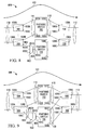
- the photonic switch 102 fails or the reliability is unacceptable it is desirable to change the routing so that all high priority traffic is passed through the secondary photonic switch 104 and all low priority traffic is passed through the primary photonic switch 102 , the head-end 2x2 switches 1306 and tail-end 2x2 switches 1308 are switched over to the positions shown in Figure 14 .
- the high-priority traffic is now re-routed from the first inputs 1306A of the head-end 2x2 switches 1306 , through the second outputs 1306D of the head-end 2x2 switches 1306 , through the connections 1318 , through the secondary photonic switch 104 , through the connections 1320 , through the second inputs 1308B of the tail-end 2x2 switches 1308 to the first outputs 1308C of the tail-end switches 1308; and the low-priority traffic on the input optical fibers 1310B, 1310D is re-routed from the second inputs 1306B of the head-end 2x2 switches 1306, through the first outputs 1306C of the head-end 2x2 switches 1306 , through the connections 1314 , through the primary photonic switch 102 , through the connections 1316 , through the first inputs 1308A of the tail-end 2x2 switches 1308 to the second outputs 1308D of the tail-end switches 1308 .
Landscapes
- Engineering & Computer Science (AREA)
- Computer Networks & Wireless Communication (AREA)
- Optical Communication System (AREA)
- Mechanical Light Control Or Optical Switches (AREA)
Abstract
Description
Claims (14)
- A photonic switch system comprising:wherein the first and second type modules are operable in combination to cause the light signal to transit either the first or second photonic switch.a first photonic switch having a plurality of inputs and outputs;a second photonic switch having a plurality of inputs and outputs;a plurality of modules of a first type each having an input port for receiving incoming light signals, a first output port and a second output port, the first output port being connectable to a respective input of the first photonic switch and the second output port being connectable to a respective input of the second photonic switch; anda plurality of modules of a second type each having an output port for transmitting outgoing light signals, a first input port and a second input port, the first input port being connectable to a respective output of the first photonic switch and the second output port being connectable to a respective output the second photonic switch,
- A system according to Claim 1, wherein each module of the plurality of a first type comprises a 1:2 splitter and each module of the plurality of a second type comprises a selected one of:a) a 2x1 switch;b) a first VOA, a second VOA and a 2:1 combiner;c) a first shutter, a second shutter and a 2:1 combiner; ord) a 2x2 switch and a performance monitor.
- A system according to Claim 1, wherein each module of the plurality of a first type comprises a 1x2 switch and each module of the plurality of a second type comprises a selected one of:a) a 2:1 combiner;b) a 2x1 switch;c) a first VOA, a second VOA, and a 2:1 combiner; ord) a first shutter, a second shutter, and 2:1 combiner.
- A system according to Claim 1, wherein each module of the plurality of a first type comprises a 1:2 splitter, a first VOA and a second VOA, and each module of the plurality of a second type comprises a selected one of:a) a 2:1 combiner;b) a 2x1 switch; orc) a first VOA, a second VOA, and a 2:1 combiner.
- A system according to Claim 1, wherein each module of the plurality of a first type comprises a 1:2 splitter, a first shutter and a second shutter, and each module of the plurality of a second type comprises either a 2:1 combiner or a 2 x 1 switch.
- A system according to Claim 1, wherein each module of the plurality of a first type comprises a 1x2 switch, a first VOA and a second VOA and each module of the plurality of a second type comprises a 2:1 combiner.
- A system according to any preceding claim, wherein the first photonic switch and the second photonic switch are an integral unit.
- A system according to any preceding claim, further comprising:a multiplexor having a plurality of inputs and an output, the plurality of inputs being connectable to respective second output ports of the module of a second type and the output of the multiplexor being connected to an input of the second photonic switch.
- A method of performing a bridge and roll operation on incoming optical signals in a photonic switch system having a first photonic switch connected such that an optical path is established only though the first photonic switch, and having a plurality of first type and second type modules and a second photonic switch, the method comprising the steps of:connecting a second output port of each module of the plurality of modules of the first type to a respective input of the second photonic switch and connecting a second input port of each module of the plurality of the second type to a respective output of the second photonic switch;re-configuring the modules of the first type and the modules of the second type so that the incoming light signals that are received on the input ports of the modules of the first type are re-routed through the second photonic switch to the output ports of the modules of the second type; anddisconnecting a first output port of each module of the first type from the first photonic switch and disconnecting a first input port of each module of a second type from the first photonic switch.
- A method according to Claim 9, further comprising the steps of:connecting the first output port of each module of a first type to a respective input of the first photonic switch and connecting the first input port of each module of a second type to a respective output of the first photonic switch;re-configuring the modules of the first type and the modules of the second type so that the incoming light signals that are received on the input ports of the modules of the first type are re-routed through the first photonic switch to the output ports of the modules of the second type to be transmitted as outgoing light signals; anddisconnecting the second output port of each module of a first type from the second photonic switch and disconnecting the first input port of each module of a second type from the second photonic switch.
- A method according to Claim 9, wherein the step of re-configuring the modules of the first type and the modules of the second type so that the incoming light signals that are received on the input ports of the modules of the first type are re-routed through the second photonic switch to the output ports of the modules of the second type to be transmitted as outgoing light signals causes an interruption of less than 50 milliseconds in the outgoing light signals.
- In a system according to Claim 8 in which only the first photonic switch is connected into the system such that an optical path is established only through the first photonic switch, a bridge and roll method comprising the steps of:connecting the second output ports of the plurality of the modules of a first type to a respective input of the multiplexor and connecting a second input port of each module of a second type to a respective output of the second photonic switch;re-configuring the modules of a first type and the modules of a second type so that the incoming light signals that are received on the input ports of the modules of a first type are re-routed through the multiplexor and through the second photonic switch to an output port of one of the modules of a second type; anddisconnecting the first output port of each module of a first type from the first photonic switch and disconnecting the first input port of each module of a second type from the first photonic switch.
- A photonic switch system comprising:wherein the first plurality of 2x2 switches and the second plurality of 2x2 switches are re-configured such that the incoming light signals that are received on the first inputs of the first plurality of 2x2 switches are routed through the first photonic switch to the first outputs of the second plurality of 2x2 switches to be transmitted as outgoing light signals; and incoming light signals that are received on the second inputs of the first plurality of 2x2 switches are routed through the second photonic switch to the second outputs of the second plurality of 2x2 switches to be transmitted as outgoing light signals.a first photonic switch having a plurality of inputs and a plurality of outputs;a second photonic switch having a plurality of inputs and a plurality of outputs;a first plurality of 2x2 switches each having a first input and a second input to receive incoming light signals, a first output and a second output, the first output of each of the first plurality of 2x2 switches being connected to a respective input of a first photonic switch and the second output of each of the first plurality of 2x2 switches being connected to a respective input of the second photonic switch; anda second plurality of 2x2 switches each having a first input and a second input, a first output and a second output for transmitting outgoing light signals, the first input of each of the second plurality of 2x2 switches being connected to a respective output of the first photonic switch and the second input of each of the second plurality of 2x2 switches being connected to a respective output of the second photonic switch,
- In a system according to Claim 13, a method for re-routing the incoming light signals that are received on the first inputs of the first plurality of 2x2 switches through the second photonic switch to the first outputs of the second plurality of 2x2 switches, and re-routing the incoming light signals that are received on the second inputs of the first plurality of 2x2 switches through the first photonic switch to the second outputs of the second plurality of 2x2 switches, the method comprising the step of:re-configuring the first plurality of 2x2 switches and the second plurality of 2x2 switches so that the incoming light signals that are received on the first inputs of the first plurality of 2x2 switches are re-routed through the second photonic switch to the first outputs of the second plurality of 2x2 switches and the incoming light signals that are received on the second inputs of the first plurality of 2x2 switches are re-routed through the first photonic switch to the second outputs of the second plurality of 2x2 switches.
Applications Claiming Priority (2)
| Application Number | Priority Date | Filing Date | Title |
|---|---|---|---|
| US09/850,130 US6643423B2 (en) | 2001-05-08 | 2001-05-08 | System and method for bridge and roll in a photonic switch |
| US850130 | 2001-05-08 |
Publications (2)
| Publication Number | Publication Date |
|---|---|
| EP1258756A2 true EP1258756A2 (en) | 2002-11-20 |
| EP1258756A3 EP1258756A3 (en) | 2004-10-27 |
Family
ID=25307338
Family Applications (1)
| Application Number | Title | Priority Date | Filing Date |
|---|---|---|---|
| EP02253197A Ceased EP1258756A3 (en) | 2001-05-08 | 2002-05-08 | Photonic switch |
Country Status (3)
| Country | Link |
|---|---|
| US (1) | US6643423B2 (en) |
| EP (1) | EP1258756A3 (en) |
| CA (1) | CA2385215A1 (en) |
Families Citing this family (7)
| Publication number | Priority date | Publication date | Assignee | Title |
|---|---|---|---|---|
| US7609918B2 (en) * | 2002-05-28 | 2009-10-27 | Optun (Bvi) Ltd. | Method and apparatus for optical mode division multiplexing and demultiplexing |
| US7218814B2 (en) * | 2002-05-28 | 2007-05-15 | Optun (Bvi) Ltd. | Method and apparatus for optical mode conversion |
| US7321705B2 (en) | 2002-05-28 | 2008-01-22 | Optun (Bvi) Ltd. | Method and device for optical switching and variable optical attenuation |
| US20040109683A1 (en) * | 2002-08-21 | 2004-06-10 | Meriton Networks Inc. | Non-disruptive lightpath routing changes in WDM networks |
| US7400832B2 (en) * | 2004-09-30 | 2008-07-15 | Nextg Networks, Inc. | Resilient switch |
| US9054828B2 (en) * | 2011-10-14 | 2015-06-09 | Glimmerglass Networks, Inc. | Method and system for managing optical distribution network |
| EP2856253B1 (en) * | 2012-05-24 | 2016-08-24 | Raytheon Company | High power optical switch |
Family Cites Families (7)
| Publication number | Priority date | Publication date | Assignee | Title |
|---|---|---|---|---|
| JP3006680B2 (en) * | 1997-01-31 | 2000-02-07 | 日本電気株式会社 | Optical transmission equipment |
| JPH10257580A (en) * | 1997-03-11 | 1998-09-25 | Fujitsu Ltd | Cross connect device |
| JPH11239100A (en) * | 1998-02-20 | 1999-08-31 | Fujitsu Ltd | Optical wavelength multiplexing system with redundant configuration |
| DE59909541D1 (en) * | 1998-11-17 | 2004-06-24 | Siemens Ag | METHOD FOR UNINTERRUPTIBLE EXTENSION OF THE COUPLING PANEL OF A COMMUNICATION SYSTEM |
| FR2789538B1 (en) * | 1999-02-04 | 2001-03-30 | Cit Alcatel | SWITCHING MODULES, SWITCHING MATRIX CONTAINING SUCH MODULES, AND NON-BLOCKING MODULAR SWITCHING NETWORK CONTAINING SUCH A MATRIX |
| US6597826B1 (en) * | 1999-11-02 | 2003-07-22 | Xros, Inc. | Optical cross-connect switching system with bridging, test access and redundancy |
| CA2310293A1 (en) * | 2000-05-30 | 2001-11-30 | Alan F. Graves | Photonic network node |
-
2001
- 2001-05-08 US US09/850,130 patent/US6643423B2/en not_active Expired - Lifetime
-
2002
- 2002-05-07 CA CA002385215A patent/CA2385215A1/en not_active Abandoned
- 2002-05-08 EP EP02253197A patent/EP1258756A3/en not_active Ceased
Also Published As
| Publication number | Publication date |
|---|---|
| US6643423B2 (en) | 2003-11-04 |
| EP1258756A3 (en) | 2004-10-27 |
| CA2385215A1 (en) | 2002-11-08 |
| US20020168129A1 (en) | 2002-11-14 |
Similar Documents
| Publication | Publication Date | Title |
|---|---|---|
| JP3006680B2 (en) | Optical transmission equipment | |
| CA2285128C (en) | Switch for optical signals | |
| US6072610A (en) | Optical transmission system | |
| US20020126350A1 (en) | Optical path cross-connect and optical wavelength multiplexing diversity communication system using the same | |
| US20040190901A1 (en) | Bi-directional optical network element and its control protocols for WDM rings | |
| US9014562B2 (en) | Optical line terminal arrangement, apparatus and methods | |
| JP2004536485A (en) | Method and apparatus for optically and transparently transmitting a wavelength multiplex signal between different wavelength multiplex optical communication systems | |
| JP2006191212A (en) | Optical node and optical add / drop multiplexer | |
| US20060120718A1 (en) | Optical transmission apparatus and optical transmission system | |
| US6816680B2 (en) | Optical communications network and nodes for forming such a network | |
| EP1064739B1 (en) | Protection of wdm-channels | |
| US7003189B1 (en) | Optical fiber protection switch | |
| US6990268B2 (en) | Optical wavelength cross connect architectures using wavelength routing elements | |
| US20020071154A1 (en) | Shared optical ring protection in a multi-fiber ring | |
| CA2385215A1 (en) | System and method for bridge and roll in a photonic switch | |
| JP4676657B2 (en) | Optical add / drop multiplexer | |
| US6813408B2 (en) | Methods for performing in-service upgrades of optical wavelength cross connects | |
| US7450843B2 (en) | Optical communication system with two parallel transmission paths | |
| US7187865B2 (en) | Hybrid photonic/electronic switching in a multi-channel network | |
| US6922530B1 (en) | Method and apparatus for optical channel switching in an optical add/drop multiplexer | |
| EP1120987A1 (en) | Cross-connect protection | |
| US6735390B1 (en) | Method and apparatus for terminating optical links in an optical network | |
| EP1483607B1 (en) | Optical wavelength cross connect architectures using wavelength routing elements and methods for performing in-service upgrades | |
| Chang et al. | Multicasting optical crossconnects with fault tolerance mechanism and wavelength routing in all-optical networks | |
| US6594413B2 (en) | Optical switching device |
Legal Events
| Date | Code | Title | Description |
|---|---|---|---|
| PUAI | Public reference made under article 153(3) epc to a published international application that has entered the european phase |
Free format text: ORIGINAL CODE: 0009012 |
|
| AK | Designated contracting states |
Kind code of ref document: A2 Designated state(s): AT BE CH CY DE DK ES FI FR GB GR IE IT LI LU MC NL PT SE TR |
|
| AX | Request for extension of the european patent |
Free format text: AL;LT;LV;MK;RO;SI |
|
| RIN1 | Information on inventor provided before grant (corrected) |
Inventor name: LALONDE, FREDERICK J. Inventor name: GRUBER, JOHN G. |
|
| PUAL | Search report despatched |
Free format text: ORIGINAL CODE: 0009013 |
|
| AK | Designated contracting states |
Kind code of ref document: A3 Designated state(s): AT BE CH CY DE DK ES FI FR GB GR IE IT LI LU MC NL PT SE TR |
|
| AX | Request for extension of the european patent |
Extension state: AL LT LV MK RO SI |
|
| 17P | Request for examination filed |
Effective date: 20050407 |
|
| AKX | Designation fees paid |
Designated state(s): DE FR GB |
|
| STAA | Information on the status of an ep patent application or granted ep patent |
Free format text: STATUS: THE APPLICATION HAS BEEN REFUSED |
|
| 18R | Application refused |
Effective date: 20061019 |