EP1258743A2 - Imaging optical instrument - Google Patents
Imaging optical instrument Download PDFInfo
- Publication number
- EP1258743A2 EP1258743A2 EP02009974A EP02009974A EP1258743A2 EP 1258743 A2 EP1258743 A2 EP 1258743A2 EP 02009974 A EP02009974 A EP 02009974A EP 02009974 A EP02009974 A EP 02009974A EP 1258743 A2 EP1258743 A2 EP 1258743A2
- Authority
- EP
- European Patent Office
- Prior art keywords
- lens
- lens barrel
- aperture stop
- beams
- aperture
- Prior art date
- Legal status (The legal status is an assumption and is not a legal conclusion. Google has not performed a legal analysis and makes no representation as to the accuracy of the status listed.)
- Granted
Links
Images


Classifications
-
- G—PHYSICS
- G02—OPTICS
- G02B—OPTICAL ELEMENTS, SYSTEMS OR APPARATUS
- G02B3/00—Simple or compound lenses
- G02B3/02—Simple or compound lenses with non-spherical faces
- G02B3/06—Simple or compound lenses with non-spherical faces with cylindrical or toric faces
-
- G—PHYSICS
- G02—OPTICS
- G02B—OPTICAL ELEMENTS, SYSTEMS OR APPARATUS
- G02B13/00—Optical objectives specially designed for the purposes specified below
- G02B13/22—Telecentric objectives or lens systems
-
- G—PHYSICS
- G02—OPTICS
- G02B—OPTICAL ELEMENTS, SYSTEMS OR APPARATUS
- G02B3/00—Simple or compound lenses
-
- G—PHYSICS
- G02—OPTICS
- G02B—OPTICAL ELEMENTS, SYSTEMS OR APPARATUS
- G02B5/00—Optical elements other than lenses
- G02B5/001—Axicons, waxicons, reflaxicons
-
- G—PHYSICS
- G02—OPTICS
- G02B—OPTICAL ELEMENTS, SYSTEMS OR APPARATUS
- G02B5/00—Optical elements other than lenses
- G02B5/005—Diaphragms
-
- G—PHYSICS
- G02—OPTICS
- G02B—OPTICAL ELEMENTS, SYSTEMS OR APPARATUS
- G02B7/00—Mountings, adjusting means, or light-tight connections, for optical elements
- G02B7/02—Mountings, adjusting means, or light-tight connections, for optical elements for lenses
-
- G—PHYSICS
- G02—OPTICS
- G02B—OPTICAL ELEMENTS, SYSTEMS OR APPARATUS
- G02B7/00—Mountings, adjusting means, or light-tight connections, for optical elements
- G02B7/02—Mountings, adjusting means, or light-tight connections, for optical elements for lenses
- G02B7/021—Mountings, adjusting means, or light-tight connections, for optical elements for lenses for more than one lens
-
- G—PHYSICS
- G02—OPTICS
- G02B—OPTICAL ELEMENTS, SYSTEMS OR APPARATUS
- G02B7/00—Mountings, adjusting means, or light-tight connections, for optical elements
- G02B7/02—Mountings, adjusting means, or light-tight connections, for optical elements for lenses
- G02B7/028—Mountings, adjusting means, or light-tight connections, for optical elements for lenses with means for compensating for changes in temperature or for controlling the temperature; thermal stabilisation
-
- G—PHYSICS
- G03—PHOTOGRAPHY; CINEMATOGRAPHY; ANALOGOUS TECHNIQUES USING WAVES OTHER THAN OPTICAL WAVES; ELECTROGRAPHY; HOLOGRAPHY
- G03B—APPARATUS OR ARRANGEMENTS FOR TAKING PHOTOGRAPHS OR FOR PROJECTING OR VIEWING THEM; APPARATUS OR ARRANGEMENTS EMPLOYING ANALOGOUS TECHNIQUES USING WAVES OTHER THAN OPTICAL WAVES; ACCESSORIES THEREFOR
- G03B27/00—Photographic printing apparatus
- G03B27/32—Projection printing apparatus, e.g. enlarger, copying camera
Definitions
- the present invention relates to an imaging optical instrument for imaging light from an object on a recording surface.
- an imaging optical instrument includes an aperture stop disposed in an optical system for limiting beams contributing to image formation, in order to secure excellent imaging performance or to secure a required focal depth.
- an aperture stop is formed of a light-shielding sheet of metal or plastic defining a circular or polygonal aperture. The aperture stop is fixed inside a sealed space defined by lenses and a barrel holding the lenses.
- high power lasers are used as light sources to emit light for forming images on a recording surface
- light of high energy level enters the optical instrument from the objects.
- the aperture stop is heated to a high temperature as a result of shielding the high energy light.
- the heat of the aperture stop reaches the lens barrel by thermal conduction, and may deform the lens barrel locally. Such a deformation disrupts a proper positional relationship between the lenses to lower imaging performance.
- the heat of the aperture stop filling the lens barrel interior by thermal convection heats up and expands the entire lens barrel. This results in an imaging position shifting along the optical axis.
- the aperture stop itself may melt or vaporize to lose its light-shielding function.
- the shielding material may adhere to lens surfaces to lower optical efficiency also.
- the object of the present invention is to provide an imaging optical instrument capable of effectively preventing an increase in the temperature of an aperture stop.
- an imaging optical instrument for causing light incident at an entrance end of a lens barrel to pass through an aperture stop and thereafter to leave the lens barrel from an exit end thereof, thereby imaging on a recording surface
- the aperture stop comprises an optical element having a passage portion formed centrally thereof for allowing passage of beams that should contribute to image formation, and a refracting portion surrounding the passage portion for refracting beams that should be intercepted and causing the beams that should be intercepted to leave the lens barrel from the exit end.
- This imaging optical instrument is capable of effectively preventing an increase in the temperature of the aperture stop and lens barrel.
- the aperture stop comprises an optical element having an aperture formed centrally thereof for allowing passage of beams that should contribute to image formation, and a refracting portion surrounding the aperture for refracting beams that should be intercepted and causing the beams that should be intercepted to leave the lens barrel from the exit end. That is, the aperture formed in the optical element is used as the passage portion for allowing passage of the beams.
- the aperture stop comprises an optical element having a parallel plate portion formed centrally thereof for allowing passage of beams that should contribute to image formation, and a refracting portion surrounding the parallel plate portion for refracting beams that should be intercepted and causing the beams that should be intercepted to leave the lens barrel from the exit end. That is, the parallel plate portion formed in the optical element is used as the passage portion for allowing passage of the beams.
- an imaging optical instrument for causing light incident at an entrance end of a lens barrel to pass through an aperture stop and thereafter to leave the lens barrel from an exit end thereof, thereby imaging on a recording surface
- the aperture stop comprises an optical element having an aperture formed centrally thereof for allowing passage of beams that should contribute to image formation, and a reflecting portion surrounding the aperture for reflecting beams that should be intercepted and causing the beams that should be intercepted to leave the lens barrel from the entrance end.
- an imaging optical instrument for causing light incident at an entrance end of a lens barrel to pass through an aperture stop and thereafter to leave the lens barrel from an exit end thereof, thereby imaging on a recording surface
- the aperture stop comprises a plurality of light-shielding plates arranged at predetermined intervals along an optical axis of the lens barrel and defining apertures with diameters thereof varying stepwise, the lens barrel defining a vent hole adjacent the aperture stop.
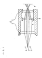
- FIG. 1 is a sectional side view of an imaging optical instrument in a first embodiment of the invention.
- This imaging optical instrument is designed for causing light emitted from a plurality of light sources 2 arranged adjacent an object to image on a recording surfaces 8 of a photosensitive or thermosensitive material.
- the imaging optical instrument includes a lens barrel 3 having a lens 4 disposed adjacent an entrance end of the lens barrel 3 and a lens 5 disposed adjacent an exit end of the lens barrel 3 to act as a two-sided telecentric optical system 6, and an aperture stop 7.
- This imaging optical instrument is used, for example, in an image recording apparatus that records images by scanning the photosensitive or thermosensitive material with beams modulated by image signals.
- the light sources 2 are formed of semiconductor lasers or light emitting diodes, for example. Further, the light sources 2 may be in the form of ends of a plurality of optical fibers connected to semiconductor lasers or light emitting diodes, or a group of openings illuminated by semiconductor lasers or light emitting diodes. These light sources 2 are arranged to emit light having intensity gravities running parallel to one another, and preferably parallel to the optical axis of the two-sided telecentric optical system 6.
- the two-sided telecentric optical system 6 includes, in the simplest form, two positive lenses 4 and 5 spaced from each other by a sum of focal lengths thereof.
- the arrangement of the light sources 2 is magnified or reduced by the two-sided telecentric optical system 6 into an arrangement of luminous points for recording images with a desired resolution on the recording surface 8. Since the principal rays in the beams emitted from the light sources 2 are parallel to one another, the arrangement of luminous points remains constant even when the recording surface 8 deviates forward or rearward from an imaging plane. Thus, images may be recorded with high precision.
- the aperture stop 7 is disposed adjacent a meeting point of a rearward focus of the lens 4 and a forward focus of the lens 5.
- FIG. 2 is an explanatory view schematically showing various aperture stops 7a, 7b and 7c (which may be referred to collectively as "aperture stop 7").
- aperture stop 7 Each of Figs. 2 (a), 2 (b) and 2 (c) includes a side view at left and a front view at right.
- Figs. 2 (a), 2 (b) and 2 (c) show various configurations with exaggeration.
- the aperture stop 7 shown in Fig. 1 corresponds to the aperture stop 7a shown in Fig. 2 (a).
- the aperture stop 7a is formed by drilling a plano-convex lens as shown in phantom in the side view at the left of Fig. 2 (a).
- the aperture stop 7a has an aperture 72 formed centrally thereof to act as a passage of light, and a refracting portion 71 surrounding the aperture 72 to refract the light.
- the aperture 72 has an inside diameter corresponding to an aperture diameter required of the aperture stop 7a. This aperture diameter determines an NA (number of apertures) of the beams used in recording images.
- the aperture diameter is determined by taking optical efficiency and focal depth into account.
- the two-sided telecentric optical system 6 causes these beams to form images of the light sources 2 on the recording surface 8.
- the parts that should be intercepted i.e. the parts that should not contribute to image formation
- the refracting portion 71 of the aperture stop 7a As shown in hatching in Fig. 1, such parts of the beams, after exiting the lens barrel 3 reach around the imaging points which are formed by the beams having passed through the aperture 72 of the aperture stop 7a without forming images and without being condensed.
- the density of light energy in these areas may be made far less than the density of light energy at the imaging point on the recording surface 8 of the light having passed through the aperture 72 of the aperture stop 7a.
- an image is recorded without being affected by the light reaching the areas around the imaging point without forming images and without being condensed.
- the aperture stop 7a allows the unwanted light to leave the lens barrel 3 from the exit end thereof instead of intercepting such unwanted light. Consequently, this imaging optical instrument effectively avoids the generation of heat occurring in the prior art.
- the shape of refracting portion 71 of the aperture stop 7a (i.e. the shape of the plano-convex lens used as stock) must be such that the beams thereby refracted do not impinge on inner walls of the lens barrel 3, but reach the areas around the imaging point on the recording surface 8 without forming images and without being condensed.
- the refracting portion 71 has an excessively low level of refractive power, the beams having passed through the refracting portion 71 would reach small areas around the imaging point on the recording surface 8. The density of light energy in these areas is not sufficiently lowered, thereby to produce an adverse effect on image recording.
- a permissible level of light energy of the beams passing through the refracting portion 71 for producing no adverse effect on image recording is dependent chiefly on the characteristics of a recording medium set to the recording surface 8.
- the refracting portion 71 has an excessively high level of refractive power
- the beams having passed through the refracting portion 71 would impinge on the inner walls of the lens barrel 3 to be absorbed and converted to heat by the inner walls. This gives rise to such problems as deterioration in imaging performance and displacement of an imaging position.
- a high degree of profile irregularity is not required of the refracting portion 71 of the aperture stop 7a, which allows the aperture stop 7a to be manufactured by using an inexpensive plano-convex lens or the like.
- a large aberration is provided in order to reduce the energy density of the beams reaching areas around an imaging point without forming images and without being condensed.
- the above aperture stop 7a may be replaced by the aperture stop 7b shown in Fig. 2 (b) or the aperture stop 7c shown in Fig. 2 (c).
- the aperture stop 7b shown in Fig. 2 (b) is formed by drilling a cone prism as shown in phantom in the side view at the left of Fig. 2 (b).
- the aperture stop 7b has an aperture 75 formed centrally thereof, and a refracting portion 74 surrounding the aperture 75 to refract the light.
- the aperture 75 has an inside diameter corresponding to an aperture diameter required of the aperture stop 7b.
- this aperture stop 7b When this aperture stop 7b is used, as when the above aperture stop 7a is used, of the beams emitted from the light sources 2, the parts that should contribute to image formation pass straight through the aperture 75 of the aperture stop 7b. Consequently, the two-sided telecentric optical system 6 causes these beams to form images of the light sources 2 on the recording surface 8. On the other hand, of the beams emitted from the light sources 2, the parts that should be intercepted are refracted by the refracting portion 74 of the aperture stop 7b. Such parts of the beams reach areas around the imaging point without forming images and without being condensed.
- the beams are in the state of nearly parallel beams where the aperture stop 7 is installed.
- variations in the incident angle and exit angle may be reduced. This facilitates optimization of an antireflection coating usually applied to this type of optical element, and assures an improved antireflection effect. Consequently, heat generation adjacent the aperture stop 7b may be more effectively suppressed than where the foregoing aperture stop 7a is used.
- the aperture stop 7c shown in Fig. 2 (c) is formed by cutting and polishing a surface area 79 of a plano-convex lens as shown in phantom in the side view at the left Fig. 2 (c).
- the aperture stop 7c has a parallel plate portion 78 formed centrally thereof to act as a light passage, and a refracting portion 77 surrounding the parallel plate portion 78 to refract the light.
- the parallel plate portion 78 has a diameter corresponding to an aperture diameter required of the aperture stop 7c.
- this aperture stop 7c When this aperture stop 7c is used, as when the above aperture stop 7a or 7b is used, of the beams emitted from the light sources 2, the parts that should contribute to image formation pass straight through the parallel plate portion 78 of the aperture stop 7c. Consequently, the two-sided telecentric optical system 6 causes these beams to form images of the light sources 2 on the recording surface 8. On the other hand, of the beams emitted from the light sources 2, the parts that should be intercepted are refracted by the refracting portion 77 of the aperture stop 7c. Such parts of the beams reach areas around the imaging point without forming images and without being condensed.
- aperture stops 7a and 7b parts of the beams emitted from light sources 2 arranged off the optical axis could enter the refracting portions 71 and 74 through inner walls of apertures 72 and 75 to be absorbed, scattered or reflected. This would cause a temperature increase adjacent the aperture stops 7a and 7b, or lower imaging performance because of flares.
- the aperture stop 7c is free from such problems. However, when this aperture stop 7c is used, the entire system including the parallel plate portion 78 must be designed with aberration corrections.
- a plano-convex lens or prism is used for the aperture stop 7.
- a flattened lens such as a Fresnel lens or graded index lens may be used.
- a diffracting optical element may be used.
- FIG. 3 is a sectional side view of an imaging optical instrument in a second embodiment.
- Like reference numerals are used to identify like parts which are the same as in the first embodiment and will not be described again.
- the foregoing imaging optical instrument in the first embodiment refracts the beams that should be intercepted and allows these beams to leave the lens barrel 3 from the exit end thereof.
- the imaging optical instrument in the second embodiment reflects the beams that should be intercepted and allows these beams to leave the lens barrel 3 from the entrance end thereof.
- This imaging optical instrument employs an aperture stop 7 similar to the aperture stop 7a shown in Fig. 2 (a), and formed of a plano-convex lens having a central aperture, but with a reflective coating 70 applied to the convex surface thereof (opposed to the recording surface 8 shown in Fig. 3).
- the aperture of this aperture stop 7 has an inside diameter corresponding to the aperture diameter required of the aperture stop 7.
- the parts that should contribute to image formation pass straight through the aperture of the aperture stop 7. Consequently, the two-sided telecentric optical system 6 causes these beams to form images of the light sources 2 on the recording surface 8.
- the aperture stop 7 allows the unwanted light to leave the lens barrel 3, from the entrance end thereof in this embodiment, instead of intercepting such light. Consequently, this imaging optical instrument effectively avoids the generation of heat occurring in the prior art.
- the shape of reflective coating 70 on the aperture stop 7 (i.e. the shape of the plano-convex lens used as stock) must be such that the beams thereby reflected do not impinge on the inner walls of the lens barrel 3, but exit from the entrance end.
- a plano-convex lens is used as stock for forming the aperture stop 7 to determine the shape of reflective coating 70.
- An element other than a lens may be used.
- a plane mirror defining a central opening may be used.
- FIG. 4 is a sectional side view of an imaging optical instrument in a third embodiment.
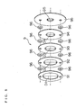
- Fig. 5 is an exploded perspective view of an aperture stop in the third embodiment.
- Like reference numerals are used to identify like parts which are the same as in the first and second embodiments and will not be described again.
- the imaging optical instruments in the first and second embodiments described hereinbefore cause the beams that should be intercepted to leave the lens barrel 3 from the exit or entrance end thereof.
- the imaging optical instrument in the third embodiment is constructed to shield and absorb the beams that should be intercepted.
- an aperture stop 9 employed in the imaging optical instrument in the third embodiment has five thin light-shielding plates 91, 92, 93, 94 and 95 arranged, with spacers 96 in between, along the optical axis of the lens barrel 3.
- the five light-shielding plates 91, 92, 93, 94 and 95 define apertures having aperture diameters D1, D2, D3, D4 and D5, respectively.
- the aperture diameters D1, D2, D3, D4 and D5 are progressively smaller from the light-shielding plate 91 to the light-shielding plate 95.
- the diameter D5 of the aperture in the light-shielding plate 95 corresponds to an aperture diameter required of the aperture stop 9.
- the lens barrel 3 has an opening formed adjacent the aperture stop 7, with a filter 31 fitted.in the opening for removing foreign matters.
- the lens barrel 3 has a further opening formed in a position opposed to the above opening, with an exhaust fan 32 fitted therein.
- each of the light-shielding plates 91, 92, 93, 94 and 95 bears its share in shielding the beams emitted from the light sources 2. This effectively avoids a sharp increase in the temperature of the light-shielding plates 91, 92, 93, 94 and 95.
- the light-shielding plates 91, 92, 93, 94 and 95 are arranged with the spacers 96 in between, and these spacers 96 have a heat radiating effect comparable to that of heat radiating fins.
- the light-shielding plates 91, 92, 93, 94 and 95 are prevented from being heated to a high temperature.
- Air ascending in the lens barrel 3 as a result of heat radiation from the light-shielding plates 91, 92, 93, 94 and 95 is discharged from the lens barrel 3 by the exhaust fan 32.
- Fresh air is supplied into the lens barrel 3 through the filter 31 that removes foreign matters. This prevents the interior of the lens barrel 3 from becoming heated to a high temperature.
- the filter 31 for removing foreign matters effectively prevents dust and the like from entering the lens barrel 3.
- the imaging optical instrument according to the invention is applied to an image recording apparatus.
- the imaging optical instrument according to the invention is not limited to such application.
Landscapes
- Physics & Mathematics (AREA)
- General Physics & Mathematics (AREA)
- Optics & Photonics (AREA)
- Lenses (AREA)
- Lens Barrels (AREA)
- Diaphragms For Cameras (AREA)
Abstract
Description
Claims (13)
- An imaging optical instrument for causing light incident at an entrance end of a lens barrel to pass through an aperture stop and thereafter to leave the lens barrel from an exit end thereof, thereby imaging on a recording surface,
wherein said aperture stop comprises an optical element having a passage portion formed centrally thereof for allowing passage of beams that should contribute to image formation, and a refracting portion surrounding said passage portion for refracting beams that should be intercepted and causing said beams that should be intercepted to leave said lens barrel from said exit end. - An imaging optical instrument as defined in claim 1, wherein said aperture stop comprises an optical element having an aperture formed centrally thereof for allowing passage of beams that should contribute to image formation, and a refracting portion surrounding said aperture for refracting beams that should be intercepted and. causing said beams that should be intercepted to leave said lens barrel from said exit end.
- An imaging optical instrument as defined in claim 2, further comprising a two-sided telecentric optical system including a first lens disposed adjacent said entrance end of said lens barrel, and a second lens disposed adjacent said exit end of said lens barrel, said aperture stop being disposed adjacent a meeting point of a rearward focus of the first lens and a forward focus of the second lens.
- An imaging optical instrument as defined in claim 3, wherein said optical element is a lens having an aperture formed centrally thereof.
- An imaging optical instrument as defined in claim 3, wherein said optical element is a prism having an aperture formed centrally thereof.
- An imaging optical instrument as defined in claim 1, wherein said aperture stop comprises an optical element having a parallel plate portion formed centrally thereof for allowing passage of beams that should contribute to image formation, and a refracting portion surrounding said parallel plate portion for refracting beams that should be intercepted and causing said beams that should be intercepted to leave said lens barrel from said exit end.
- An imaging optical instrument as defined in claim 6, further comprising a two-sided telecentric optical system including a first lens disposed adjacent said entrance end of said lens barrel, and a second lens disposed adjacent said exit end of said lens barrel, said aperture stop being disposed adjacent a meeting point of a rearward focus of the first lens and a forward focus of the second lens.
- An imaging optical instrument for causing light incident at an entrance end of a lens barrel to pass through an aperture stop and thereafter to leave the lens barrel from an exit end thereof, thereby imaging on a recording surface,
wherein said aperture stop comprises an optical element having an aperture formed centrally thereof for allowing passage of beams that should contribute to image formation, and a reflecting portion surrounding said aperture for reflecting beams that should be intercepted and causing said beams that should be intercepted to leave said lens barrel from said entrance end. - An imaging optical instrument as defined in claim 8, further comprising a two-sided telecentric optical system including a first lens disposed adjacent said entrance end of said lens barrel, and a second lens disposed adjacent said exit end of said lens barrel, said aperture stop being disposed adjacent a meeting point of a rearward focus of the first lens and a forward focus of the second lens.
- An imaging optical instrument for causing light incident at an entrance end of a lens barrel to pass through an aperture stop and thereafter to leave the lens barrel from an exit end thereof, thereby imaging on a recording surface,
wherein said aperture stop comprises a plurality of light-shielding plates arranged at predetermined intervals along an optical axis of said lens barrel and defining apertures with diameters thereof varying stepwise, said lens barrel defining a vent hole adjacent said aperture stop. - An imaging optical instrument as defined in claim 10, further comprising a two-sided telecentric optical system including a first lens disposed adjacent said entrance end of said lens barrel, and a second lens disposed adjacent said exit end of said lens barrel, said aperture stop being disposed adjacent a meeting point of a rearward focus of the first lens and a forward focus of the second lens.
- An imaging optical instrument as defined in claim 11, further comprising forced ventilation means mounted in said vent hole.
- An imaging optical instrument as defined in claim 11, further comprising a filter mounted in said vent hole for removing foreign matters.
Priority Applications (1)
| Application Number | Priority Date | Filing Date | Title |
|---|---|---|---|
| EP05026108.0A EP1637909B1 (en) | 2001-05-14 | 2002-05-03 | Imaging optical instrument |
Applications Claiming Priority (2)
| Application Number | Priority Date | Filing Date | Title |
|---|---|---|---|
| JP2001142585 | 2001-05-14 | ||
| JP2001142585A JP3710724B2 (en) | 2001-05-14 | 2001-05-14 | Imaging optical device |
Related Child Applications (1)
| Application Number | Title | Priority Date | Filing Date |
|---|---|---|---|
| EP05026108.0A Division EP1637909B1 (en) | 2001-05-14 | 2002-05-03 | Imaging optical instrument |
Publications (3)
| Publication Number | Publication Date |
|---|---|
| EP1258743A2 true EP1258743A2 (en) | 2002-11-20 |
| EP1258743A3 EP1258743A3 (en) | 2004-05-12 |
| EP1258743B1 EP1258743B1 (en) | 2008-04-02 |
Family
ID=18988864
Family Applications (2)
| Application Number | Title | Priority Date | Filing Date |
|---|---|---|---|
| EP02009974A Expired - Lifetime EP1258743B1 (en) | 2001-05-14 | 2002-05-03 | Imaging optical instrument |
| EP05026108.0A Expired - Lifetime EP1637909B1 (en) | 2001-05-14 | 2002-05-03 | Imaging optical instrument |
Family Applications After (1)
| Application Number | Title | Priority Date | Filing Date |
|---|---|---|---|
| EP05026108.0A Expired - Lifetime EP1637909B1 (en) | 2001-05-14 | 2002-05-03 | Imaging optical instrument |
Country Status (4)
| Country | Link |
|---|---|
| US (2) | US6816237B2 (en) |
| EP (2) | EP1258743B1 (en) |
| JP (1) | JP3710724B2 (en) |
| DE (1) | DE60225867T2 (en) |
Cited By (7)
| Publication number | Priority date | Publication date | Assignee | Title |
|---|---|---|---|---|
| WO2006036896A1 (en) * | 2004-09-28 | 2006-04-06 | Honeywell International Inc. | A cytometer having telecentric optics |
| WO2006091253A3 (en) * | 2004-12-03 | 2006-11-30 | Microvision Inc | Aperture plate and related sytem and method |
| EP1714790A3 (en) * | 2005-04-20 | 2008-06-04 | Dainippon Screen Mfg. Co., Ltd. | Image recording apparatus |
| EP3098640A3 (en) * | 2015-05-28 | 2017-01-25 | Mitutoyo Corporation | Telecentric optical apparatus |
| WO2018234024A1 (en) * | 2017-06-21 | 2018-12-27 | Trumpf Laser Gmbh | Device for coupling radiation out of an optical fiber, optical cable, and machining head having said device |
| US10495849B2 (en) | 2016-02-17 | 2019-12-03 | Samsung Electronics Co., Ltd. | Optical lens assembly and apparatus having the same |
| EP3771936A1 (en) * | 2019-07-30 | 2021-02-03 | Ricoh Company, Ltd. | Laser unit, laser marker, and laser printing system |
Families Citing this family (28)
| Publication number | Priority date | Publication date | Assignee | Title |
|---|---|---|---|---|
| JP4217415B2 (en) * | 2001-04-04 | 2009-02-04 | オリンパス株式会社 | Electronic imaging device |
| JP4508521B2 (en) * | 2002-07-16 | 2010-07-21 | オリンパス株式会社 | Imaging device |
| JP4223851B2 (en) * | 2003-03-31 | 2009-02-12 | ミツミ電機株式会社 | Small camera module |
| JP2004302064A (en) * | 2003-03-31 | 2004-10-28 | Fuji Photo Optical Co Ltd | Laser array imaging lens and image forming apparatus |
| WO2005006416A1 (en) * | 2003-07-09 | 2005-01-20 | Nikon Corporation | Linking unit, exposure apparatus and method for manufacturing device |
| EP1503244A1 (en) | 2003-07-28 | 2005-02-02 | ASML Netherlands B.V. | Lithographic projection apparatus and device manufacturing method |
| JP4666900B2 (en) * | 2003-10-23 | 2011-04-06 | キヤノン株式会社 | Projection lens barrel and projection-type image display device |
| JP2005201935A (en) * | 2004-01-13 | 2005-07-28 | Fujinon Corp | Projection lens |
| JP2006017818A (en) * | 2004-06-30 | 2006-01-19 | Konica Minolta Opto Inc | Assembly lens and manufacturing method thereof |
| JP2006222222A (en) * | 2005-02-09 | 2006-08-24 | Canon Inc | Projection optical system and exposure apparatus having the same |
| CN101191887A (en) * | 2006-11-27 | 2008-06-04 | 鸿富锦精密工业(深圳)有限公司 | Lens module and assembly method thereof |
| TWI385471B (en) * | 2006-11-27 | 2013-02-11 | Hon Hai Prec Ind Co Ltd | Lens module and method for assembling same |
| JP5163021B2 (en) * | 2007-09-10 | 2013-03-13 | 株式会社リコー | MONITOR DEVICE, LIGHT SOURCE DEVICE, OPTICAL SCANNING DEVICE, AND IMAGE FORMING DEVICE |
| EP2070909A1 (en) * | 2007-12-15 | 2009-06-17 | Bayer Schering Pharma AG | Non-steroidal progesterone receptor modulators |
| JP5097086B2 (en) * | 2008-11-13 | 2012-12-12 | パナソニック株式会社 | Imaging optical system and imaging apparatus using the same |
| US8507862B2 (en) | 2011-02-25 | 2013-08-13 | Tyco Fire & Security Gmbh | Low profile light collimator micro baffle and method |
| WO2014142854A1 (en) * | 2013-03-13 | 2014-09-18 | Ofs Fitel, Llc | Collimating and concentrating light into an optical fiber |
| US20150309283A1 (en) * | 2014-03-21 | 2015-10-29 | Lensbaby, Llc | Auxiliary camera lens |
| US9841378B2 (en) * | 2014-05-01 | 2017-12-12 | Bio-Rad Laboratories, Inc. | Series absorbance glass and interference filters |
| US9971135B2 (en) | 2014-05-10 | 2018-05-15 | Innovations In Optics, Inc. | Light emitting diode digital micromirror device illuminator |
| JP6695629B2 (en) * | 2015-05-28 | 2020-05-20 | 株式会社ミツトヨ | Telecentric optical device |
| JP6883939B2 (en) * | 2015-09-14 | 2021-06-09 | 株式会社ミツトヨ | Photoelectric encoder |
| US10969569B2 (en) * | 2015-12-28 | 2021-04-06 | Wethe Lab Co., Ltd. | Light source-integrated lens assembly and optical apparatus including the same |
| EP3409014B1 (en) | 2016-01-26 | 2020-10-28 | Imax Corporation | Stereo image projection with high intra-frame contrast |
| IL267910B2 (en) * | 2017-01-19 | 2024-04-01 | Innovations In Optics Inc | A digital micromirror lighting device with a light emitting diode |
| CN111344605B (en) * | 2017-11-14 | 2023-10-20 | 图像影院国际有限公司 | Light adjustment for cinema direct-view displays |
| CN114526457A (en) * | 2020-11-23 | 2022-05-24 | 常州星宇车灯股份有限公司 | Sunlight simulator |
| CN119380611B (en) * | 2024-12-11 | 2025-10-21 | 大连理工大学 | An optical experiment demonstration device used in physics teaching |
Family Cites Families (35)
| Publication number | Priority date | Publication date | Assignee | Title |
|---|---|---|---|---|
| US3259733A (en) * | 1961-02-24 | 1966-07-05 | Chevron Res | Automatic integrator for chromatograph records |
| US3365724A (en) * | 1965-12-20 | 1968-01-23 | Dresser Systems Inc | Dual presentation oscillographic recorder |
| US3500049A (en) * | 1967-04-17 | 1970-03-10 | Bendix Corp | Variable albedo earth sensor of a relatively narrow angular effective field of view |
| US3698797A (en) * | 1970-04-27 | 1972-10-17 | Us Navy | Laser output attenuator |
| DE2239620C3 (en) * | 1972-08-11 | 1982-02-04 | Dornier System Gmbh, 7990 Friedrichshafen | Projection device for exposing spherical surfaces |
| US4128752A (en) * | 1976-12-15 | 1978-12-05 | Her Majesty The Queen In Right Of Canada, As Represented By The Minister Of National Defence | Laser micromachining apparatus |
| JPS53135096A (en) * | 1977-04-28 | 1978-11-25 | Nec Corp | Laser processing apparatus |
| JPS63108318A (en) * | 1986-10-27 | 1988-05-13 | Nikon Corp | Laser processing equipment |
| DE3818129C2 (en) * | 1988-05-27 | 2003-04-10 | Lambda Physik Ag | Device for limiting laser beams |
| JPH01176807U (en) * | 1988-05-31 | 1989-12-18 | ||
| JPH02107111U (en) * | 1989-02-09 | 1990-08-27 | ||
| JP2535031Y2 (en) * | 1989-02-09 | 1997-05-07 | 旭光学工業株式会社 | Lens shading frame |
| US5181238A (en) * | 1989-05-31 | 1993-01-19 | At&T Bell Laboratories | Authenticated communications access service |
| JP2691029B2 (en) * | 1989-10-18 | 1997-12-17 | 株式会社日立製作所 | Laser equipment |
| JP2816735B2 (en) * | 1990-02-15 | 1998-10-27 | 旭光学工業株式会社 | Aperture mechanism of zoom lens |
| JPH04113185A (en) | 1990-09-03 | 1992-04-14 | Matsushita Electric Ind Co Ltd | Cooling system |
| JPH04113185U (en) * | 1991-03-08 | 1992-10-02 | 富士電線電器株式会社 | light heating device |
| US5424552A (en) * | 1991-07-09 | 1995-06-13 | Nikon Corporation | Projection exposing apparatus |
| US5212589A (en) * | 1991-10-25 | 1993-05-18 | International Business Machines Corporation | Lens system for focussing light of plural wavelength |
| JPH05192782A (en) * | 1992-01-21 | 1993-08-03 | Fanuc Ltd | Laser beam machine |
| US5339123A (en) * | 1992-09-10 | 1994-08-16 | Nikon Corporation | Data imprinting device for camera |
| US5592335A (en) * | 1993-03-23 | 1997-01-07 | Nikon Corporation | Reduced diameter camera lens barrel with lens shift device and improved focus lens drive linkage |
| US5364493A (en) * | 1993-05-06 | 1994-11-15 | Litel Instruments | Apparatus and process for the production of fine line metal traces |
| JPH0786152A (en) * | 1993-09-14 | 1995-03-31 | Nikon Corp | Projection exposure device |
| JPH0792348A (en) * | 1993-09-21 | 1995-04-07 | Toshiba Corp | Laser light injection device for optical fiber |
| JPH08106043A (en) * | 1994-10-05 | 1996-04-23 | Fuji Photo Optical Co Ltd | Objective lens for endoscope |
| JPH09308023A (en) | 1996-05-08 | 1997-11-28 | Yaskawa Electric Corp | switchboard |
| JP3960640B2 (en) * | 1996-05-20 | 2007-08-15 | コニカミノルタホールディングス株式会社 | Optical system for recording and / or reproducing optical information recording medium |
| JPH10209028A (en) * | 1997-01-16 | 1998-08-07 | Nikon Corp | Illumination optical device and method for manufacturing semiconductor element |
| DE19910725A1 (en) * | 1998-03-12 | 1999-10-14 | Fraunhofer Ges Forschung | Aperture for high density laser radiation minimizes absorption heating |
| JP2000075185A (en) * | 1998-08-31 | 2000-03-14 | Nikon Corp | Lens barrel |
| WO2000014588A1 (en) * | 1998-09-07 | 2000-03-16 | Carl Zeiss Jena Gmbh | Device for improving the beam product |
| US6347178B1 (en) * | 1999-11-01 | 2002-02-12 | Gsi Lumonics Ltd. | Optical fibre apparatus |
| JP2002090654A (en) * | 2000-09-12 | 2002-03-27 | Olympus Optical Co Ltd | Intermediate lens barrel having projection optical system, and microscope having projection optical system |
| US6724546B2 (en) * | 2002-04-25 | 2004-04-20 | Mitsubishi Denki Kabushiki Kaisha | Light converging optical system for converging light onto a reflecting optical-spatial modulator element and image displaying apparatus for displaying an image formed by light reflected by the reflecting optical-spatial modulator element |
-
2001
- 2001-05-14 JP JP2001142585A patent/JP3710724B2/en not_active Expired - Fee Related
-
2002
- 2002-05-03 EP EP02009974A patent/EP1258743B1/en not_active Expired - Lifetime
- 2002-05-03 EP EP05026108.0A patent/EP1637909B1/en not_active Expired - Lifetime
- 2002-05-03 DE DE60225867T patent/DE60225867T2/en not_active Expired - Lifetime
- 2002-05-14 US US10/143,789 patent/US6816237B2/en not_active Expired - Lifetime
-
2004
- 2004-10-25 US US10/971,106 patent/US6927924B2/en not_active Expired - Lifetime
Cited By (19)
| Publication number | Priority date | Publication date | Assignee | Title |
|---|---|---|---|---|
| US7283223B2 (en) | 2002-08-21 | 2007-10-16 | Honeywell International Inc. | Cytometer having telecentric optics |
| WO2006036896A1 (en) * | 2004-09-28 | 2006-04-06 | Honeywell International Inc. | A cytometer having telecentric optics |
| WO2006091253A3 (en) * | 2004-12-03 | 2006-11-30 | Microvision Inc | Aperture plate and related sytem and method |
| US7277213B2 (en) | 2004-12-03 | 2007-10-02 | Microvision, Inc. | Aperture plate and related system and method |
| EP1714790A3 (en) * | 2005-04-20 | 2008-06-04 | Dainippon Screen Mfg. Co., Ltd. | Image recording apparatus |
| US7535625B2 (en) | 2005-04-20 | 2009-05-19 | Dainippon Screen Mfg. Co., Ltd. | Image recording apparatus |
| CN111427137B (en) * | 2015-05-28 | 2022-04-19 | 株式会社三丰 | Telecentric optical device |
| EP3098640A3 (en) * | 2015-05-28 | 2017-01-25 | Mitutoyo Corporation | Telecentric optical apparatus |
| EP4325259A3 (en) * | 2015-05-28 | 2024-04-24 | Mitutoyo Corporation | Telecentric optical apparatus |
| US10520710B2 (en) | 2015-05-28 | 2019-12-31 | Mitutoyo Corporation | Telecentric optical apparatus |
| US11467384B2 (en) | 2015-05-28 | 2022-10-11 | Mitutoyo Corporation | Telecentric optical apparatus |
| CN111427137A (en) * | 2015-05-28 | 2020-07-17 | 株式会社三丰 | Telecentric optics |
| US10495849B2 (en) | 2016-02-17 | 2019-12-03 | Samsung Electronics Co., Ltd. | Optical lens assembly and apparatus having the same |
| EP3391117B1 (en) * | 2016-02-17 | 2025-01-15 | Samsung Electronics Co., Ltd. | Optical lens assembly and apparatus having the same |
| CN110770617B (en) * | 2017-06-21 | 2022-04-15 | 通快激光有限责任公司 | Device for coupling out radiation from an optical fiber, optical fiber cable and machining head |
| US10830953B2 (en) | 2017-06-21 | 2020-11-10 | Trumpf Laser Gmbh | Apparatuses for coupling radiation out of an optical fiber |
| CN110770617A (en) * | 2017-06-21 | 2020-02-07 | 通快激光有限责任公司 | Device for coupling out radiation from an optical fiber, optical fiber cable and machining head |
| WO2018234024A1 (en) * | 2017-06-21 | 2018-12-27 | Trumpf Laser Gmbh | Device for coupling radiation out of an optical fiber, optical cable, and machining head having said device |
| EP3771936A1 (en) * | 2019-07-30 | 2021-02-03 | Ricoh Company, Ltd. | Laser unit, laser marker, and laser printing system |
Also Published As
| Publication number | Publication date |
|---|---|
| EP1258743B1 (en) | 2008-04-02 |
| US6816237B2 (en) | 2004-11-09 |
| EP1637909B1 (en) | 2014-04-30 |
| US20050083587A1 (en) | 2005-04-21 |
| JP2002341222A (en) | 2002-11-27 |
| US20020167652A1 (en) | 2002-11-14 |
| EP1637909A2 (en) | 2006-03-22 |
| DE60225867T2 (en) | 2009-04-09 |
| EP1637909A3 (en) | 2006-04-12 |
| US6927924B2 (en) | 2005-08-09 |
| EP1258743A3 (en) | 2004-05-12 |
| DE60225867D1 (en) | 2008-05-15 |
| JP3710724B2 (en) | 2005-10-26 |
Similar Documents
| Publication | Publication Date | Title |
|---|---|---|
| US6816237B2 (en) | Imaging optical instrument | |
| KR102841260B1 (en) | Luminous device imaging the lit surfaces of at least two collectors | |
| DK2467635T3 (en) | LED flashlight, especially LED floodlight | |
| JP4792486B2 (en) | Optical system for Fresnel lens light, especially spotlight or floodlight | |
| JP2593430B2 (en) | Illumination optical system for endoscope | |
| US5931576A (en) | Optical coupler for distributive lighting system | |
| JP7019824B2 (en) | Automatic vehicle floodlight equipped with a light-shielding diaphragm that blocks incident sunlight | |
| US10731817B2 (en) | Luminous module comprising a matrix array of light sources and a bifocal optical system | |
| US7517088B1 (en) | Light projector | |
| JP2008257015A (en) | Lighting device | |
| JP2003532960A (en) | Traffic light traffic light | |
| JP2005157358A (en) | Refractivity/diffractive hybrid type lens for beam shaping specially for high output diode laser | |
| JP4549109B2 (en) | Illumination device and photographing device | |
| JP7784851B2 (en) | Vehicle lamp and automobile including same | |
| KR102419044B1 (en) | Light Source Assembly | |
| JP2001119530A (en) | One-dimensional image sensor device | |
| JP2906543B2 (en) | Lighting system for micro reader printer | |
| JP2000122178A5 (en) | ||
| JPH10241437A (en) | Light source device, illumination system, and image projection device | |
| EP3771936A1 (en) | Laser unit, laser marker, and laser printing system | |
| US20050254124A1 (en) | Microscope | |
| JP2006208682A (en) | Lighting optical device and optical device | |
| CN116125736A (en) | Projection system and manufacturing method thereof | |
| JPH1178115A (en) | Optical device | |
| JPH1195109A (en) | Optical scanner for confocal |
Legal Events
| Date | Code | Title | Description |
|---|---|---|---|
| PUAI | Public reference made under article 153(3) epc to a published international application that has entered the european phase |
Free format text: ORIGINAL CODE: 0009012 |
|
| AK | Designated contracting states |
Kind code of ref document: A2 Designated state(s): AT BE CH CY DE DK ES FI FR GB GR IE IT LI LU MC NL PT SE TR |
|
| AX | Request for extension of the european patent |
Free format text: AL;LT;LV;MK;RO;SI |
|
| RIC1 | Information provided on ipc code assigned before grant |
Ipc: 7G 02B 3/00 B Ipc: 7G 02B 5/00 B Ipc: 7G 02B 7/02 A |
|
| PUAL | Search report despatched |
Free format text: ORIGINAL CODE: 0009013 |
|
| AK | Designated contracting states |
Kind code of ref document: A3 Designated state(s): AT BE CH CY DE DK ES FI FR GB GR IE IT LI LU MC NL PT SE TR |
|
| AX | Request for extension of the european patent |
Extension state: AL LT LV MK RO SI |
|
| 17P | Request for examination filed |
Effective date: 20040812 |
|
| AKX | Designation fees paid |
Designated state(s): DE FR GB |
|
| 17Q | First examination report despatched |
Effective date: 20050520 |
|
| GRAP | Despatch of communication of intention to grant a patent |
Free format text: ORIGINAL CODE: EPIDOSNIGR1 |
|
| GRAS | Grant fee paid |
Free format text: ORIGINAL CODE: EPIDOSNIGR3 |
|
| GRAA | (expected) grant |
Free format text: ORIGINAL CODE: 0009210 |
|
| AK | Designated contracting states |
Kind code of ref document: B1 Designated state(s): DE FR GB |
|
| REG | Reference to a national code |
Ref country code: GB Ref legal event code: FG4D |
|
| RIN1 | Information on inventor provided before grant (corrected) |
Inventor name: UEYAMA, KENJI,C/O DAINIPPON SCREEN MFG. CO., LTD. |
|
| REF | Corresponds to: |
Ref document number: 60225867 Country of ref document: DE Date of ref document: 20080515 Kind code of ref document: P |
|
| ET | Fr: translation filed | ||
| PLBE | No opposition filed within time limit |
Free format text: ORIGINAL CODE: 0009261 |
|
| STAA | Information on the status of an ep patent application or granted ep patent |
Free format text: STATUS: NO OPPOSITION FILED WITHIN TIME LIMIT |
|
| 26N | No opposition filed |
Effective date: 20090106 |
|
| REG | Reference to a national code |
Ref country code: DE Ref legal event code: R082 Ref document number: 60225867 Country of ref document: DE Representative=s name: KILIAN KILIAN & PARTNER, DE |
|
| REG | Reference to a national code |
Ref country code: DE Ref legal event code: R082 Ref document number: 60225867 Country of ref document: DE Representative=s name: KILIAN KILIAN & PARTNER, DE |
|
| REG | Reference to a national code |
Ref country code: DE Ref legal event code: R082 Ref document number: 60225867 Country of ref document: DE Representative=s name: KILIAN KILIAN & PARTNER MBB PATENTANWAELTE, DE Effective date: 20130130 Ref country code: DE Ref legal event code: R082 Ref document number: 60225867 Country of ref document: DE Representative=s name: KILIAN KILIAN & PARTNER MBB PATENTANWAELTE, DE Effective date: 20150317 Ref country code: DE Ref legal event code: R081 Ref document number: 60225867 Country of ref document: DE Owner name: SCREEN HOLDINGS CO., LTD., JP Free format text: FORMER OWNER: DAINIPPON SCREEN MFG. CO., LTD., KYOTO, JP Effective date: 20150317 Ref country code: DE Ref legal event code: R082 Ref document number: 60225867 Country of ref document: DE Representative=s name: KILIAN KILIAN & PARTNER, DE Effective date: 20150317 Ref country code: DE Ref legal event code: R082 Ref document number: 60225867 Country of ref document: DE Representative=s name: KILIAN KILIAN & PARTNER, DE Effective date: 20130130 |
|
| REG | Reference to a national code |
Ref country code: FR Ref legal event code: CD Owner name: SCREEN HOLDINGS CO., LTD. Effective date: 20150622 |
|
| REG | Reference to a national code |
Ref country code: FR Ref legal event code: PLFP Year of fee payment: 15 |
|
| REG | Reference to a national code |
Ref country code: FR Ref legal event code: PLFP Year of fee payment: 16 |
|
| REG | Reference to a national code |
Ref country code: FR Ref legal event code: PLFP Year of fee payment: 17 |
|
| PGFP | Annual fee paid to national office [announced via postgrant information from national office to epo] |
Ref country code: DE Payment date: 20190423 Year of fee payment: 18 |
|
| PGFP | Annual fee paid to national office [announced via postgrant information from national office to epo] |
Ref country code: FR Payment date: 20190410 Year of fee payment: 18 |
|
| PGFP | Annual fee paid to national office [announced via postgrant information from national office to epo] |
Ref country code: GB Payment date: 20190501 Year of fee payment: 18 |
|
| REG | Reference to a national code |
Ref country code: DE Ref legal event code: R119 Ref document number: 60225867 Country of ref document: DE |
|
| GBPC | Gb: european patent ceased through non-payment of renewal fee |
Effective date: 20200503 |
|
| PG25 | Lapsed in a contracting state [announced via postgrant information from national office to epo] |
Ref country code: FR Free format text: LAPSE BECAUSE OF NON-PAYMENT OF DUE FEES Effective date: 20200531 Ref country code: GB Free format text: LAPSE BECAUSE OF NON-PAYMENT OF DUE FEES Effective date: 20200503 |
|
| PG25 | Lapsed in a contracting state [announced via postgrant information from national office to epo] |
Ref country code: DE Free format text: LAPSE BECAUSE OF NON-PAYMENT OF DUE FEES Effective date: 20201201 |