EP1258657A1 - Toroidal continuously variable transmission and method of manufacturing the transmission - Google Patents
Toroidal continuously variable transmission and method of manufacturing the transmission Download PDFInfo
- Publication number
- EP1258657A1 EP1258657A1 EP01981075A EP01981075A EP1258657A1 EP 1258657 A1 EP1258657 A1 EP 1258657A1 EP 01981075 A EP01981075 A EP 01981075A EP 01981075 A EP01981075 A EP 01981075A EP 1258657 A1 EP1258657 A1 EP 1258657A1
- Authority
- EP
- European Patent Office
- Prior art keywords
- input
- disk
- continuously variable
- toroidal continuously
- variable transmission
- Prior art date
- Legal status (The legal status is an assumption and is not a legal conclusion. Google has not performed a legal analysis and makes no representation as to the accuracy of the status listed.)
- Granted
Links
Images



Classifications
-
- C—CHEMISTRY; METALLURGY
- C21—METALLURGY OF IRON
- C21D—MODIFYING THE PHYSICAL STRUCTURE OF FERROUS METALS; GENERAL DEVICES FOR HEAT TREATMENT OF FERROUS OR NON-FERROUS METALS OR ALLOYS; MAKING METAL MALLEABLE, e.g. BY DECARBURISATION OR TEMPERING
- C21D9/00—Heat treatment, e.g. annealing, hardening, quenching or tempering, adapted for particular articles; Furnaces therefor
- C21D9/0068—Heat treatment, e.g. annealing, hardening, quenching or tempering, adapted for particular articles; Furnaces therefor for particular articles not mentioned below
-
- F—MECHANICAL ENGINEERING; LIGHTING; HEATING; WEAPONS; BLASTING
- F16—ENGINEERING ELEMENTS AND UNITS; GENERAL MEASURES FOR PRODUCING AND MAINTAINING EFFECTIVE FUNCTIONING OF MACHINES OR INSTALLATIONS; THERMAL INSULATION IN GENERAL
- F16H—GEARING
- F16H15/00—Gearings for conveying rotary motion with variable gear ratio, or for reversing rotary motion, by friction between rotary members
- F16H15/02—Gearings for conveying rotary motion with variable gear ratio, or for reversing rotary motion, by friction between rotary members without members having orbital motion
- F16H15/04—Gearings providing a continuous range of gear ratios
- F16H15/06—Gearings providing a continuous range of gear ratios in which a member A of uniform effective diameter mounted on a shaft may co-operate with different parts of a member B
- F16H15/32—Gearings providing a continuous range of gear ratios in which a member A of uniform effective diameter mounted on a shaft may co-operate with different parts of a member B in which the member B has a curved friction surface formed as a surface of a body of revolution generated by a curve which is neither a circular arc centered on its axis of revolution nor a straight line
- F16H15/36—Gearings providing a continuous range of gear ratios in which a member A of uniform effective diameter mounted on a shaft may co-operate with different parts of a member B in which the member B has a curved friction surface formed as a surface of a body of revolution generated by a curve which is neither a circular arc centered on its axis of revolution nor a straight line with concave friction surface, e.g. a hollow toroid surface
- F16H15/38—Gearings providing a continuous range of gear ratios in which a member A of uniform effective diameter mounted on a shaft may co-operate with different parts of a member B in which the member B has a curved friction surface formed as a surface of a body of revolution generated by a curve which is neither a circular arc centered on its axis of revolution nor a straight line with concave friction surface, e.g. a hollow toroid surface with two members B having hollow toroid surfaces opposite to each other, the member or members A being adjustably mounted between the surfaces
-
- C—CHEMISTRY; METALLURGY
- C21—METALLURGY OF IRON
- C21D—MODIFYING THE PHYSICAL STRUCTURE OF FERROUS METALS; GENERAL DEVICES FOR HEAT TREATMENT OF FERROUS OR NON-FERROUS METALS OR ALLOYS; MAKING METAL MALLEABLE, e.g. BY DECARBURISATION OR TEMPERING
- C21D1/00—General methods or devices for heat treatment, e.g. annealing, hardening, quenching or tempering
- C21D1/18—Hardening; Quenching with or without subsequent tempering
Definitions
- the present invention relates to a toroidal continuously variable transmission and a method of manufacturing the same. More specifically, the present invention relates to a toroidal continuously variable transmission designed for use in a vehicle, such as an automobile, and a method for manufacturing the same.
- FIG. 1 As a toroidal continuously variable transmission, the one shown in FIG. 1 has been conventionally known.
- an input disk 1 and an output disk 2 are coaxially arranged in such a manner that they face each other.
- An input shaft 3 extends through the axis of the toroidal transmission including the input and output disks 1 and 2.
- a loading cam 4 is disposed at one end of the input shaft 3. The loading cam 4 is configured to transmit the driving force (torque) of the input shaft 3 to the input disk 1 through a cam roller 5.
- the input and output disks 1 and 2 are substantially similar in shape and arranged to be symmetric.
- the facing surfaces of these disks are toroidal surfaces and jointly form substantial semicircles when viewed in a section taken axially.
- a pair of power roller bearings 6 and 7, which are in contact with the input and output disks 1 and 2, are inserted into toroidal cavities defined by the toroidal surfaces of the input and output disks 1 and 2.
- Power roller bearing 6 includes a power roller 6a which rolls on the toroidal surfaces of the input and output disks 1 and 2 (and which corresponds to an inner ring of the power roller bearing 6), an outer ring 6b and a plurality of rolling members (steel balls) 6c.
- the other power roller bearing i.e., power roller bearing 7, includes a power roller 7a which rolls on the toroidal surfaces of the input and output disks 1 and 2 (and which corresponds to an inner ring of the power roller bearing 7), an outer ring 7b and a plurality of rolling members (steel balls) 7c.
- the power roller 6a functions as the inner ring that is a structural element of the power roller bearing 6, and the power roller 7a functions as the inner ring that is a structural element of the power roller bearing 7.
- the power roller 6a is rotatably coupled to a trunnion 10 by means of a pivot 8, the outer ring 6b and the rolling members 6c, and at the same time can be inclined in such a manner that a pivot axis O, which is the center of the toroidal surfaces of the input and output disks 1 and 2, is the center of the inclining movement.
- power roller 7a is rotatably coupled to a trunnion 11 by means of a pivot 9, outer ring 7b and rolling members (steel balls) 7c, and at the same time can be inclined in such a manner that a pivot axis O, which is the center of the toroidal surfaces of the input and output disks 1 and 2, is the center of the inclining movement.
- a lubricant having a great viscosity or friction resistance is supplied onto the surfaces of the input and output disks 1 and 2 and those of the power rollers 6a and 7a.
- a driving force exerted on the input disk 1 is transmitted to the output disk 2 through a lubricant film and the power rollers 6a and 7a.
- the input and output disks 1 and 2 are independent of the input shaft 3 by means of a needle 12 interposed between them (that is, the input and output disks 1 and 2 move without reference to the rotating shaft 3).
- the output disk 2 is connected to an output shaft 14 which is parallel to the input shaft 3 and is rotatably supported by a housing (not shown) by means of angular members 13.
- the driving force of the input shaft 3 is transmitted to the loading cam 4.
- the driving force thus transmitted, rotates the loading cam 4
- the rotation is transmitted to the input disk 1 through the cam roller 5, thereby rotating the input disk 1.
- the driving force based on the rotation of the input disk 1 is transmitted to the output disk 2 by way of the power roller 6a and the power roller 7a.
- the output disk 2 rotates together with the output shaft 14.
- the trunnions 10 and 11 are moved a little toward the pivot axes O.
- the intersection between the axis of rotation of the power rollers 6a and 7a and the axis of the input and output disks 1 and 2 is shifted slightly from the original position.
- the circumferential velocity of the rotation of the power rollers 6a and 7a and that of the rotation of the input disk 1 become off balance, and part of the torque of the input disk 1 serves to rotate the power rollers 6a and 7a around the pivot axes O.
- the power rollers 6a and 7a slide and incline on the curved surfaces of the input and output disks 1 and 2.
- Jpn. Pat. Appln. KOKAI Publication No. 7-71555 is intended to provide a toroidal continuously variable transmission wherein the traction surfaces of input and output disks and those of power rollers have an improved rolling-resistant life, and wherein the input and output disks and the power rollers have an improved anti-fatigue cracking life.
- the disks and the power rollers are subjected to carbonitriding and grinding. Alternatively, they are subjected to carbonitriding and grinding, and are further processed in such a manner that at least either the disks or the power rollers have a hardened layer whose effective depth is not less than 2.0 mm and not more than 4.0 mm.
- At least one of an input disk, an output disk and a power roller is formed of medium carbon steel having a carbon content of 0.3% to 0.5%, and is subjected to carburization or carbonitriding processing and further to hardening and annealing so that the hardness of the core portion is not less than HRC35. By this processing, an improved life against fatigue is attained.
- the disks and power rollers are improved by carburization executed at a temperature in the range of 920 to 960°C or by carbonitriding processing executed at a temperature in the range of 930 to 950°C, and this process is continued 20 to 30 hours.
- a large-sized carbide or carbonitride is undesirably formed in the metal structure of the disks and power rollers. Since this carbide or carbonitride degrades the fatigue strength of the disks and power rollers, the formation of such a substance must be prevented.
- a traction drive such as a toroidal continuously variable transmission, the traction force exerted on the rolling surfaces gives rise to a tangential force. If a carbide or carbonitride is present in a crystalline grain boundary, a stress tends to concentrate at such a position, causing cracks. As a result, peeling or fracture may occur.
- the present invention has been conceived to solve the above problems, and is intended to provide a toroidal continuously variable transmission which has an improved life against fatigue by producing minute particles of carbide or carbonitride and which reduces the heat treatment cost by shortening a carburization or carbonitriding processing time.
- the present invention is also intended to provide a method for manufacturing the toroidal continuously variable transmission.
- the toroidal continuously variable transmission system of the present invention comprises: an input disk and an output disk which have traction surfaces defined between a small-diameter portion and a large-diameter portion and having an arc-shaped concave section and which are coaxially arranged such that the traction surfaces face each other; and power roller which are frictionally engagement with the traction surfaces of the input and output disks and transmit a driving force, characterized in that at least one of the input disk, the output disk and the power rollers is formed of an alloy steel which contains 0.15 to 2.0% by weight of Mo, which is subjected first to carburization or carbonitriding processing executed at a temperature not lower than 1,000°C and then to hardening and tempering, and which has a surface carbon content of 0.8 to 1.4%.
- the toroidal continuously variable transmission defined in claim 2 is characterized in that a surface nitrogen concentration is in the range of 0.04 to 0.3%.
- the invention defined in claim 3 is characterized in that at least one of the input disk, the output disk, and the power roller and outer ring of a power roller bearing has a carbon content equal or more than 0.3% and equal or less than 0.5%.
- the method of the present invention is applied to the manufacture of a toroidal continuously variable transmission comprising: an input disk and an output disk which have traction surfaces defined between a small-diameter portion and a large-diameter portion and having an arc-shaped concave section and which are coaxially arranged such that the traction surfaces face each other; and power roller which are frictionally engagement with the traction surfaces of the input and output disks and transmit a driving force, characterized in that the method comprises: forming at least one of the input disk, the output disk and the power rollers by use of an alloy steel which contains 0.15 to 2.0% by weight of Mo; executing carburization or carbonitriding processing at a temperature not lower than 1,000°C; then executing hardening and tempering, such that a surface carbon content is within the range of 0.8 to 1.4%.
- the invention defined in claim 5 is characterized in that a surface nitrogen concentration is in the range of 0.04 to 0.3%.
- the invention defined in claim 6 is characterized in that at least one of the input disk, the output disk, and the power roller and outer ring of a power roller bearing has a carbon content equal or more than 0.3% and equal or less than 0.5%.
- the toroidal continuously variable transmission undergoes both a rolling stress and a bending stress.
- cracking may occur from a nonmetallic intervening object or the like existing in a stress region, and in the worst case the rolling surfaces may peel off or fracture. It is therefore thought that in stressed regions, a residual compressive stress and a hardness are greatly dependent on the fatigue strength.
- SUJ2 is a material which has been most often used for forming a rolling bearing or a similar rolling member. This material can be provided with a hardness the rolling member requires to attain a desired life by merely executing hardening and annealing. The material, however, does not provide a residual compressive stress in the surface portion and, in some cases, results in a bending stress being generated.
- the rolling member In order to provide a hardness the rolling member requires to attain a desired life and at the same time enhance the residual compressive stress (which helps improve the strength against fracture), the input disk, the output disk and the power rollers must be subjected to surface treatment, such as carburization, or carbonitriding processing. Moreover, in order to prevent fatigue fracture from occurring at the position corresponding to a maximal shearing stress when an intense contact stress is generated, carburization or carbonitriding processing has to be executed for a long time, thereby increasing the hardness even at deep positions from the surface. Such treatment significantly increases the cost in comparison with the case where SUJ2 is used as it is.
- Patent No. 2590645 the inventors show that carbonitriding processing is preferable to. carburization because the execution of only the latter does not provide a sufficient long life against fracture and peeling. They also show that the carbonitriding processing should be preferably followed by hardening because the execution of hardening deposits minute particles of carbonitride and produces an optimal amount of residual austenite.
- Jpn. Pat. Appln. KOKAI Publication No. 6-341441 the present inventors state that the execution of carbonitriding processing at a temperature of 900°C or higher forms a deeper carbonitride layer and that decreasing a nitrogen content gradient improves grinding workability and productivity and controls the cost for heat treatment.
- the carbonitriding processing at a temperature exceeding 980°C does not necessarily ensure high performance because the amount of nitrogen contained in the surface portion of a finished product is insufficient, and inevitably requires large-scale equipment.
- a factor giving rise to this disadvantage is that the nitrogen potential for solid-solubilizing nitrogen is substantially zero at high temperature. Another factor may be a processing time.
- the low nitrogen potential hinders the impregnation of nitrogen, while the high processing temperature accelerates impregnation and diffusion of carbon and therefore shortens the processing time. This also makes the impregnation of nitrogen more difficult, and the carbonitriding processing is considered impossible eventually.
- the present inventors conducted experiments wherein carbonitriding processing was executed at a high temperature exceeding 1,000°C, and discovered that carbonitriding processing could be successfully executed at such a high temperature. A factor leading to this success lay in ingredients.
- the present inventors executed carbonitriding processing at a high temperature of 1,000°C or higher, using additives of different ingredients, and confirmed that the inclusion of Mo would remarkably increase the nitrogen content.
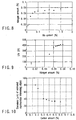
- FIG. 8 shows nitrogen content measurements made in carbonitriding processing executed at a high temperature of 1,000°C or higher.
- a toroidal continuously variable suspension undergoes both a rolling stress and a tensile stress, and cracking may occur from a nonmetallic intervening object existing in a stress region or the like. In some cases, the cracking may result in the rolling surfaces peeling off or fracture. A check was made to confirm the effects the amount of nitrogen in the surface portion might have under these conditions.
- FIG. 9 shows results of this life test.
- the surface nitrogen content should be not less than 0.04% since a nitrogen content in this range ensures a stable life despite simultaneous exertion of a rolling stress and a bending stress.
- the surface nitrogen content should preferably be not less than 0.06%.
- the surface nitrogen content exceeds 0.3%, the input disk, output disk and power roller cannot be worked with ease, and the workability is markedly degraded especially in the grinding step of the manufacturing process, resulting in poor productivity. This is why the surface nitrogen content should be not higher than 0.3%.
- the carbon content in a raw material should be high. Therefore, the carbon content is preferably set at a large value in the range of 0.3% to 0.5%.
- the rolling surfaces may peel off or fracture, with an intervening object as a starting point.
- an intervening object As a starting point.
- the size and amount of intervening objects have significant effects on the fatigue strength.
- This fact is well known in the art.
- the researches made to date show that a nonmetallic intervening object, especially an oxide object, tends to cause cracking. This being so, steel manufacturers have long made an effort to reduce the amount of nonmetallic intervening objects contained in steel.
- the present inventors discovered that when the amount of carbon contained in steel was 0.3% or more, oxide-based nonmetallic intervening objects were not much distributed in a raw material and that the diameter of maximal-size intervening objects in steel, which was estimated based on the extreme-value statistical process, decreased. For this reason and in order to shorten the carburization time, the amount of carbon in the raw material should be 0.3% or more.
- FIG. 12 shows measurements of the fatigue crack growth rate in relation to the carbon content in the raw material. As can be seen, the fatigue crack growth rate significantly increased when the carbon content in steel exceeded 0.5%. Based on this finding, the upper limit of the carbon content in the raw material was set at 0.5%.
- a toroidal continuously variable transmission can have a long life by using medium carbon steel whose carbon content in the raw material is equal or more than 0.3% and equal or less than 0.5%.
- the present inventors made researches about how the carburization or carbonitriding processing should be executed to prevent the generation of large oxides and carbonitrides.
- the carburization processing In order to attain a predetermined carburization depth in carburization or carbonitriding processing, the carburization processing should be executed at high temperature, and the higher the processing is, the shorter the processing time becomes.
- the high-temperature carburization processing increases the size of crystalline grains and decreases the ratio of the grain boundary to the micro structure. Accordingly, the carbides and carbonitrides are generated concentratedly at the grain boundary. Since, therefore, the carbides and carbonitrides can easily grow, the fatigue strength may be degraded.
- the disks and power rollers of the prior art continuously variable transmission are manufactured by executing carburization or carbonitriding processing at a temperature in the range of 930 to 960°C, because processing at a temperature in this range is free from the above problems though it is disadvantageous in light of the heat treatment efficiency.
- the present inventors discovered that minute particles of carbide were produced, when the processing temperature was set at 1,000°C or higher to shorten the processing time and the Mo content in alloy steel was set at a predetermined value to suppress the generation of the carbide and carbonitride. It was generally thought that Mo was a carbide-forming element and would increase the grain size of carbides. However, the present inventors discovered that the execution of carburization at 1,000°C or higher would produce minute particles of carbide. This phenomenon is attributed to the fact that Mo has a strong affinity for C (carbon), and Mo in the neighborhood of the grain boundary serves to take carbide or carbonitride into the inside of particles, resulting in a reduction in the size of carbide and carbonitride.
- the nitrogen distributed in the alloy produces a carbonitride, but this carbonitride is in the form of very minute particles.
- the particles of carbide or carbonitride are advantageously very minute. This phenomenon is attributable to the fact that the growth of carbide or carbonitride is slower when different kinds of elements (such as C and N) exist than when a single element (namely C) exists.
- Carburization executed at high temperature tends to produce a boundary-grain oxide in the surface layer.
- the existence of nitrogen serves to decrease the activity of oxygen, the generation of the boundary-grain oxide is suppressed in practice.
- the surface carbon content must be 0.8% or greater so as to provide the tracking surfaces of the disks and power rollers with a long life against rolling fatigue. If the surface carbon content exceeds 1.4%, the carbide at the grain boundary is inevitably large in the surface layer, particularly the surface layer portion which supports a rolling load.
- the surface nitrogen content is related to the advantage of producing minute particles of carbide or carbonitride when carbonitriding processing is executed at 1,000°C or higher.
- the surface nitrogen content is also related to the advantage of suppressing the generation of a grain-boundary oxide layer.
- the surface nitrogen content must be 0.04% or higher.
- the nitrogen content should not be higher than 0.3%, because the nitrogen content higher than this adversely affects the workability and the resultant increase in the amount of C and N gives rise to large-sized particles of carbonitride, and further degrades the fatigue strength.
- Mo which is one component of the alloy steel, is related to the advantage of producing minute particles of carbide and carbonitride when carburization or carbonitriding processing is executed at 1,000°C or higher. Mo is also related to the advantage of enabling nitriding processing, which is hard to execute at 1,000°C or higher in the prior art. To attain these advantages, the amount of Mo contained should be 0.15% by weight or more.
- the Mo content is less than 0.15% by weight, it is not possible to expect minute particles of carbide or carbonitride. On the other hand, if the Mo content exceeds 2.0% by weight, the size of the particles of carbide and carbonitride tends to increase. In consideration of the balance between these, it is preferable that the Mo content be in the range of 0.15 to 0.35% by weight.
- the C content in the alloy steel with which to form the disks and power rollers should not be less than 0.3%. If it is, an oxide-based nonmetallic intervening object, which has an adverse effect on the life against bending fatigue, is hard to remove at the time of manufacture.
- the C content should not exceed 0.5%. If it does, the fatigue crack growth rate becomes high, so that the life against fatigue cracking may be adversely affected.
- the alloy steel with which to form the disks and power rollers should contain not only Mo and Co, described above, but also Si, Mn and Cr in predetermined amounts, as will be described below.
- Si is required as a deoxidizer when steel is manufactured, it is added in an amount of 0.1% or more. Even if an extra amount of Si is added, the effect saturation occurs, and the forgeability and the grindability are adversely affected. For this reason, the Si content is preferably not more than 2.0%.
- Mn functions as a deoxidizer when steel is manufactured. In addition to this, it is an element that improves the hot-workability of steel and ensures reliable quenching characteristics. To improve the hot-workability of steel and ensure reliable quenching characteristics, therefore, Mn is added in an amount of 0.5% or more. However, if an excessive amount of Mn is added, the grindability of the raw material is degraded, and the raw material cannot be easily formed or shaped into a rolling member. For this reason, the upper limit of the Mn content range is 2.0%.
- Cr is an element that increases the amount of carbide or carbonitride which is deposited in the carburization or carbonitriding processing.
- Cr is added in an amount of 0.5% or more, the amount of carbide deposited increases, the hardness of the outermost layer increases, and the life against rolling fatigue further improves under the condition where foreign matter is included.
- the upper limit of the Cr content is 2.0%.
- the fundamental structure of the toroidal continuously variable transmission of the present invention is similar to the structure shown in FIG. 1. That is, at least one of the input disk, the output disk, and the power roller and outer ring of the power roller bearing is formed of an alloy steel which contains 0.15 to 2.0% by weight of Mo, and which is subjected to carburization or carbonitriding processing executed at a temperature not lower than 1,000°C.
- the nitrogen content in the surface portion of the finished product is equal to, or greater than 0.04 and less than 0.3%.
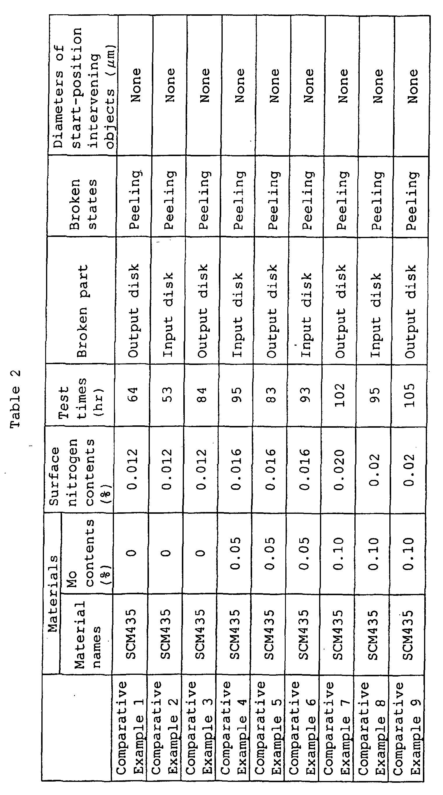
- Input disks, output disks, power rollers and outer rings of power roller bearings were manufactured using SCM415, SCM420, SCM430, SCM435, SCM440, SCM445, SCM445 with an increased carbon content of 0.6%, and SCM435 with varied Mo contents.
- the raw-material members which were to be worked as input disks and had different carbon contents were cut and ground.
- maximal-size intervening objects were estimated based on the extreme-value statistical process.
- An estimated maximal-size intervening object was measured in an area of 100 mm 2 , and 30 samples were examined using a microscope.
- the diameter of an estimated maximal-size intervening object was obtained based on a total area of 30,000 mm 2 .
- FIG. 10 shows estimated maximal-size intervening object diameters that were calculated from the carbon contents of the raw materials on the basis of the extreme-value statistical process. As can be seen, intervening objects become smaller when the carbon content is increased from 0.2% to 0.3%.
- the manufactured members namely the input disks, output disks, power rollers and outer rings were subjected to heat treatment, such as carbonitriding processing.
- the heat treatment is high-temperature carbonitriding processing executed at 1,050°C, as shown in FIG. 11.
- Step A is carbonitriding processing executed under the conditions wherein the Rx gas is 18 m 3 /hr, the carbon potential is 1.0 to 1.2%, and the remaining amount of ammonia is 0.01 to 0.1%.
- Step B is hardening
- Step C is annealing. After the heat treatment, the surfaces of the manufactured members were polished by mechanical working, such as grinding.
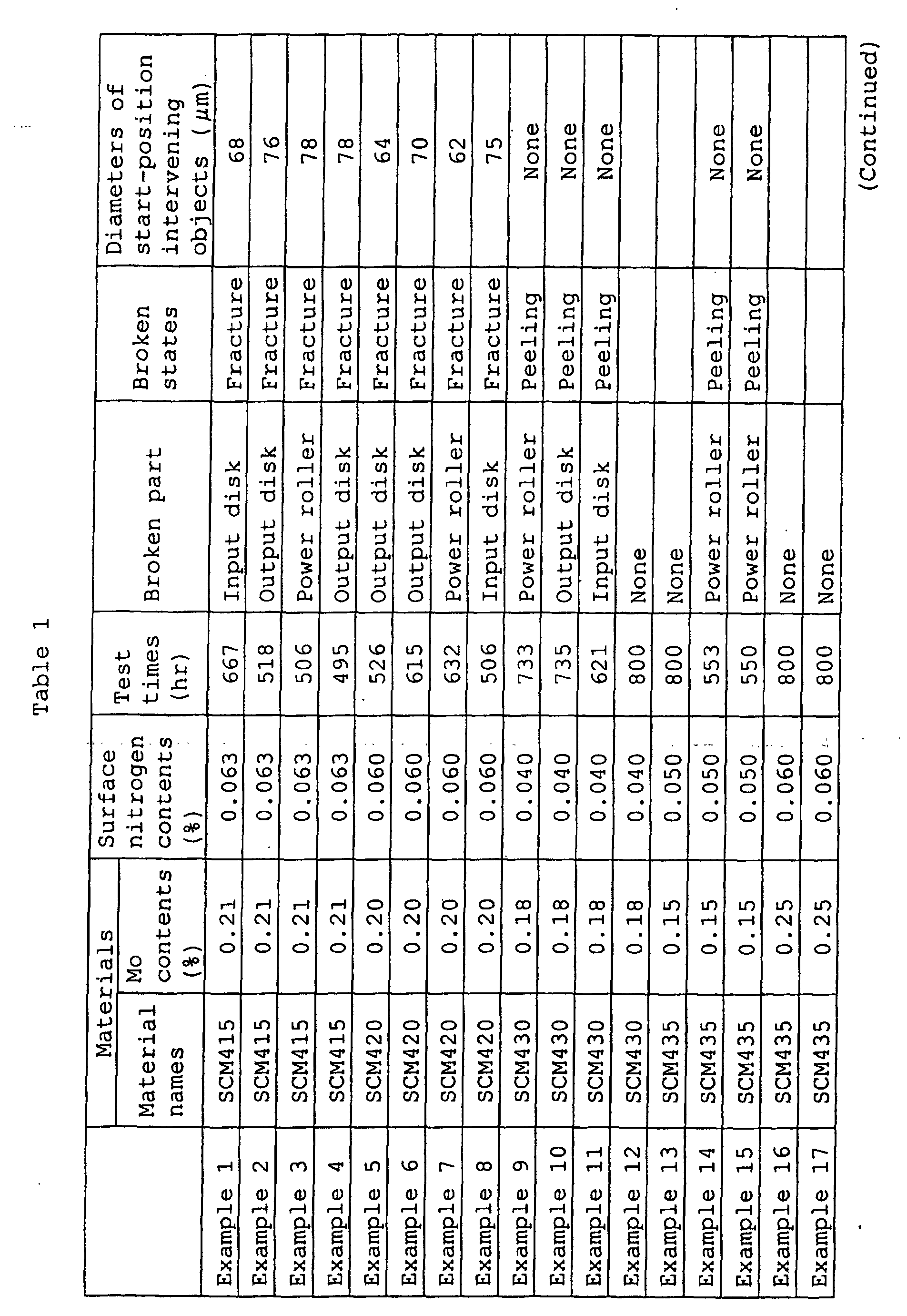
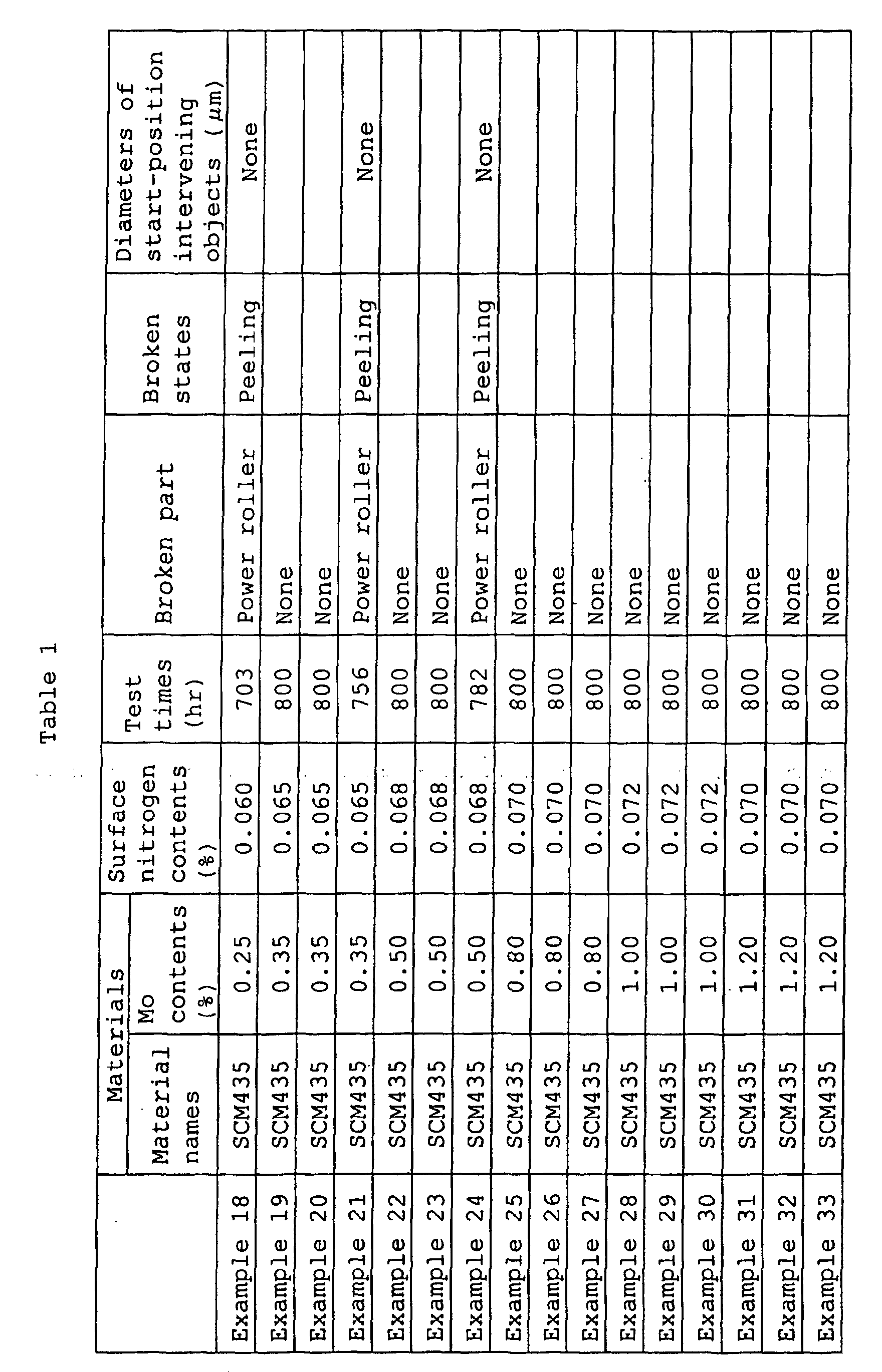
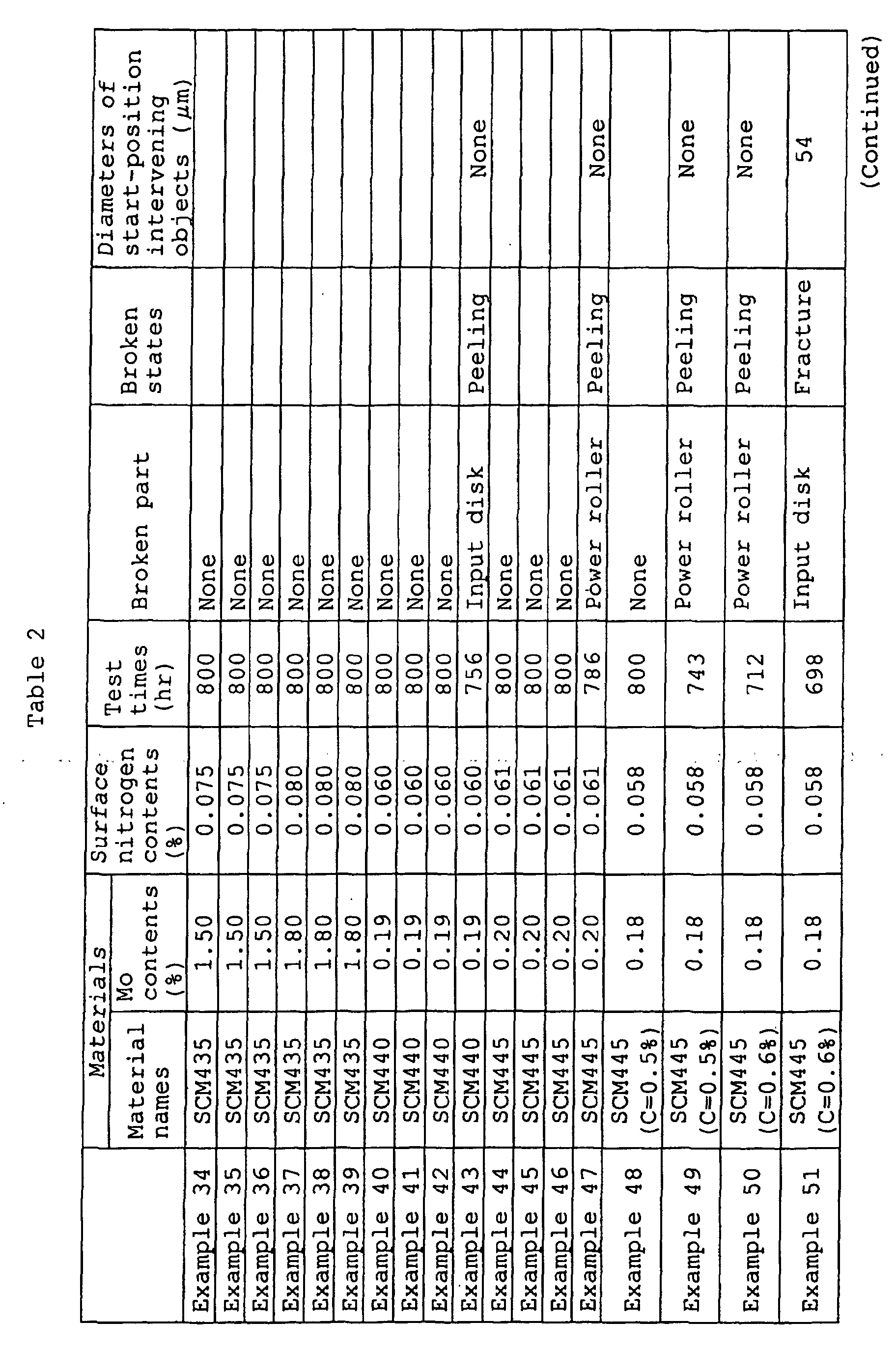
- CVTs were assembled using the input disks, output disks, power rollers and outer rings described as above, and were subjected to an endurance test.
- the input shafts were rotated by a dynamometer, and torque was applied by the dynamometer attached to the output shafts.
- the test conditions were as follows:
- the carbon contents in the raw materials be equal or more than 0.3% and equal or less than 0.5.
- At least one of the input disk, the output disk, and the power roller and the outer ring is formed of a material which contains 0.15 to 2.0% by weight of Mo, and which is subjected to carbonitriding processing executed at a temperature not lower than 1,000°C, and the surface nitrogen content of the finished product is equal to, or greater than 0.04% and less than 0.3%.
- At least one of the input disk, output disk and power roller differs from that of the conventional transmission.
- the materials listed in Table 3 below were melted.
- Material c in Table 3 was forged into a disk and ground, and then the heat treatment shown in FIG. 2 was executed.
- the carburization temperature or carbonitriding processing temperature was in the range of 920 to 1060°C and was adjusted in such a manner that the effective hardened layer (Hv 653) would have a thickness of 3 mm.
- the finishing polishing was executed, the metallic structure in a cross section was observed, and the diameter of the maximal-size carbide or nitride in the surface portion was measured.
- the diameter was measured using a microscope (magnification: 400), and image processing was performed. An area was calculated and converted into a value of a circle. Then, the diameter of the carbide or nitride was obtained.
- FIG. 3 shows relationships how a carburization temperature (a carbonitriding processing temperature) is related to the diameter of the maximal-size carbide or carbonitride.
- curved lines A illustrate carbonitriding processing
- curved lines B illustrate carburization.
- the diameter of the maximal-size carbide is as small as less than 30 ⁇ m in the case where the temperature exceeds 1,000°C.
- the diameter of the maximal-size carbonitride is as small as less than 16 ⁇ m in the case where the temperature exceeds 1,000°C.
- Step A in FIG. 2 is carburization processing, an Rx gas and an enriched gas were used (NH 3 gas was added in the case of carbonitriding processing).
- Step B is hardening, and Step C is annealing.
- the amount of ammonia remaining after the carbonitriding processing is in the range of 0.01 to 0.2%.
- the carburization or carbonitriding processing is followed by heating to a temperature higher than the A1 transformation point.
- This thermal hardening process causes recrystallization that produces minute crystal particles, and the carbide and nitrocarbide have to be in the form of minute particles in the preceding step, namely carburization or carbonitriding processing.
- the carbonitriding processing was executed at 1,000°C, and the nitriding time was determined in such a manner that the effective hardened layer (Hv 653) has a depth of 3 mm. After the subsequent finish working, the metallic structure in a cross section was observed, and the diameter of the maximal-size carbide or carbonitride in the surface portion was measured.
- FIG. 4 is a graph showing how an Mo content is related to the diameter of the maximal-size carbide or carbonitride. As can be seen from FIG. 4, when the Mo content exceeds 0.15%, the diameter of the maximal-size carbide or carbonitride is not larger than 16 ⁇ m.
- Step A in FIG. 5 is carburization processing, an Rx gas and an enriched gas were used (NH 3 gas was added in the case of carbonitriding processing).
- Step B is hardening, and Step C is annealing.
- the amount of ammonia remaining after the carbonitriding processing was in the range of 0.02 to 0.1%. Then, finish working was performed to assemble toroidal continuously variable transmissions.
- Table 5 set forth below shows inspection results of toroidal continuously variable-transmissions and tabulates the following items: materials of which to form the transmissions; heat treatment; the surface carbon content; the surface nitrogen content; the diameter of the maximal-size carbide; the diameter of the maximal-size carbonitride; the crystalline grain size in the surface portion; and the thickness of an oxide layer at the grain boundary.
- the assembled toroidal continuously variable transmissions were subjected to an endurance test under the following conditions:
- FIG. 6 shows results of an endurance test to which toroidal continuously variable transmissions were subjected.
- the transmissions were manufactured using material A shown in Table 4, and were subjected to carburization under the heat treatment conditions shown in FIG. 5.
- the transmissions had different surface carbon contents. Each transmission was broken at the track surface of the input disk.
- FIG. 7 shows results of an endurance test to which toroidal continuously variable transmissions were subjected.
- the transmissions were manufactured using material A shown in Table 4, and were subjected to carbonitriding processing under the heat treatment conditions shown in FIG. 5.
- the surface carbon contents were in the range of 1.0 to 1.1%.
- the test was ended when 1,500 hours have passed. In the cases where fracture occurred, peeling occurred at the tracking surfaces of the input disks without exception.
- the present invention is applicable not only to the inner rings of power roller bearings, which are in controlling contact with input and output disks, but also to the outer rings of the same.
- examples 52-54 do not generate large particles of a carbide in the metallic structure of a disk and a power roller. Therefore, examples 52-54 can provide toroidal continuously variable transmissions which are improved in the life against fatigue and which can be manufactured at low cost.
Landscapes
- Engineering & Computer Science (AREA)
- Chemical & Material Sciences (AREA)
- General Engineering & Computer Science (AREA)
- Mechanical Engineering (AREA)
- Physics & Mathematics (AREA)
- Thermal Sciences (AREA)
- Crystallography & Structural Chemistry (AREA)
- Materials Engineering (AREA)
- Metallurgy (AREA)
- Organic Chemistry (AREA)
- Friction Gearing (AREA)
Abstract
Description
- Rotating Speed: 4,000 r.p.m.
- output Torque: 500 Nm
- Lubrication: Traction Oil
- Oil Temperatuure: 100°C
- Speed Change Ratio: 2.0
- Outer Diameter: 140
| Material Names | Chemical compositions | ||||
| C | Si | Mn | Cr | Mo | |
| a | 0.37 | 0.22 | 0.67 | 1.10 | 0.05 |
| b | 0.36 | 0.24 | 0.68 | 1.07 | 0.10 |
| c | 0.38 | 0.23 | 0.68 | 1.09 | 0.15 |
| d | 0.35 | 0.22 | 0.69 | 1.08 | 0.49 |
| e | 0.37 | 0.21 | 0.66 | 1.11 | 1.00 |
| f | 0.37 | 0.22 | 0.67 | 1.08 | 1.50 |
| g | 0.36 | 0.21 | 0.66 | 1.10 | 1.99 |
| h | 0.37 | 0.24 | 0.69 | 1.12 | 2.50 |
| Material Names | Chemical compositions | ||||
| C | Si | Mn | Cr | Mo | |
| A | 0.38 | 0.23 | 0.70 | 1.09 | 0.20 |
| B | 0.37 | 0.05 | 0.69 | 1.10 | 0.20 |
| C | 0.36 | 2.17 | 0.71 | 1.08 | 0.22 |
| D | 0.38 | 0.24 | 0.3 | 1.08 | 0.19 |
| E | 0.37 | 0.25 | 2.09 | 1.10 | 0.21 |
| F | 0.37 | 0.25 | 0.71 | 0.3 | 0.20 |
| G | 0.37 | 0.23 | 0.69 | 2.11 | 0.20 |
| H | 0.36 | 0.24 | 0.68 | 1.07 | 0.10 |
| I | 0.37 | 0.24 | 0.69 | 1.12 | 2.50 |

- Rotating Speed: 4,000 min-1
- Input Torque: 294 Nm
- Used Oil: Synthetic Traction Oil
- Temperature of Supplied Oil: 100°C
- Speed Change Ratio: 2.0
- Outer Diameter of Disk: 140
Claims (6)
- A toroidal continuously variable transmission system of the present invention comprising:characterized in that at least one of the input disk, the output disk and the power rollers is formed of an alloy steel which contains 0.15 to 2.0% by weight of Mo, which is subjected first to carburization or carbonitriding processing executed at a temperature not lower than 1,000°C and then to hardening and tempering, and which has a surface carbon content of 0.8 to 1.4%.an input disk and an output disk which have traction surfaces defined between a small-diameter portion and a large-diameter portion and having an arc-shaped concave section and which are coaxially arranged such that the traction surfaces face each other; andpower roller which are frictionally engagement with the traction surfaces of the input and output disks and transmit a driving force,
- A toroidal continuously variable transmission according to claim 1, characterized in that a surface nitrogen content is in the range of 0.04 to 0.3%.
- A toroidal continuously variable transmission according to claim 1, characterized in that at least one of the input disk, the output disk, and the power roller and outer ring of a power roller bearing has a carbon content equal or more than 0.3% and equal or less than 0.5%.
- A method for manufacturing a toroidal continuously variable transmission comprising: an input disk and an output disk which have traction surfaces defined between a small-diameter portion and a large-diameter portion and having an arc-shaped concave section and which are coaxially arranged such that the traction surfaces face each other; and power roller which are frictionally engagement with the traction surfaces of the input and output disks and transmits a driving force, characterized by comprising: forming at least one of the input disk, the output disk and the power rollers by use of an alloy steel which contains 0.15 to 2.0% by weight of Mo; executing carburization or carbonitriding processing at a temperature not lower than 1,000°C; and then executing hardening and tempering, such that a surface carbon content is within the range of 0.8 to 1.4%.
- A method for manufacturing a toroidal continuously variable transmission according to claim 4, characterized in that a surface nitrogen concentration is in the range of 0.04 to 0.3%.
- A method for manufacturing a toroidal continuously variable transmission according to claim 4, characterized in that at least one of the input disk, the output disk, and the power roller and outer ring of a power roller bearing has a carbon content equal or more than 0.3% and equal or less than 0.5%.
Applications Claiming Priority (3)
| Application Number | Priority Date | Filing Date | Title |
|---|---|---|---|
| JP2000345206 | 2000-11-13 | ||
| JP2000345206 | 2000-11-13 | ||
| PCT/JP2001/009875 WO2002038984A1 (en) | 2000-11-13 | 2001-11-12 | Toroidal continuously variable transmission and method of manufacturing the transmission |
Publications (3)
| Publication Number | Publication Date |
|---|---|
| EP1258657A1 true EP1258657A1 (en) | 2002-11-20 |
| EP1258657A4 EP1258657A4 (en) | 2004-12-15 |
| EP1258657B1 EP1258657B1 (en) | 2006-03-29 |
Family
ID=18819277
Family Applications (1)
| Application Number | Title | Priority Date | Filing Date |
|---|---|---|---|
| EP01981075A Expired - Lifetime EP1258657B1 (en) | 2000-11-13 | 2001-11-12 | Toroidal continuously variable transmission and method of manufacturing the transmission |
Country Status (5)
| Country | Link |
|---|---|
| US (1) | US6659909B2 (en) |
| EP (1) | EP1258657B1 (en) |
| JP (1) | JPWO2002038984A1 (en) |
| DE (1) | DE60118423T2 (en) |
| WO (1) | WO2002038984A1 (en) |
Families Citing this family (15)
| Publication number | Priority date | Publication date | Assignee | Title |
|---|---|---|---|---|
| JP3783507B2 (en) * | 2000-02-16 | 2006-06-07 | 日本精工株式会社 | Machining method of toroidal type continuously variable transmission disk |
| JP2002130411A (en) * | 2000-10-20 | 2002-05-09 | Nsk Ltd | Toroidal type continuously variable transmission |
| US7438477B2 (en) * | 2001-11-29 | 2008-10-21 | Ntn Corporation | Bearing part, heat treatment method thereof, and rolling bearing |
| EP1411142B1 (en) * | 2002-10-17 | 2006-03-08 | Ntn Corporation | Full-type rolling bearing and roller cam follower for engine |
| JP4718781B2 (en) * | 2003-02-28 | 2011-07-06 | Ntn株式会社 | Transmission components and tapered roller bearings |
| US7334943B2 (en) * | 2003-02-28 | 2008-02-26 | Ntn Corporation | Differential support structure, differential's component, method of manufacturing differential support structure, and method of manufacturing differential's component |
| JP2004301321A (en) | 2003-03-14 | 2004-10-28 | Ntn Corp | Bearing for alternator and bearing for pulley |
| JP4785346B2 (en) * | 2003-03-31 | 2011-10-05 | Ntn株式会社 | Support structure of drive shaft in scroll compressor, inner ring, outer ring or rolling element of rolling bearing, and manufacturing method thereof |
| JP4152283B2 (en) * | 2003-08-29 | 2008-09-17 | Ntn株式会社 | Heat treatment method for bearing parts |
| US7594762B2 (en) | 2004-01-09 | 2009-09-29 | Ntn Corporation | Thrust needle roller bearing, support structure receiving thrust load of compressor for car air-conditioner, support structure receiving thrust load of automatic transmission, support structure for continuously variable transmission, and support structure receivin |
| JP4540351B2 (en) * | 2004-01-15 | 2010-09-08 | Ntn株式会社 | Steel heat treatment method and bearing part manufacturing method |
| JP2007046717A (en) * | 2005-08-10 | 2007-02-22 | Ntn Corp | Rolling-contact shaft with joint claw |
| CN102676983B (en) * | 2011-03-11 | 2014-03-26 | 青岛德盛机械制造有限公司 | Carburization processing method |
| EP2714944B1 (en) * | 2011-05-25 | 2020-08-12 | Aktiebolaget SKF | Method for heat treating a steel component |
| US10202666B2 (en) | 2013-03-15 | 2019-02-12 | United Technologies Corporation | Process for treating steel alloys for gears |
Family Cites Families (9)
| Publication number | Priority date | Publication date | Assignee | Title |
|---|---|---|---|---|
| JP3604415B2 (en) | 1993-08-31 | 2004-12-22 | 日本精工株式会社 | Toroidal continuously variable transmission |
| JP3525471B2 (en) * | 1994-01-18 | 2004-05-10 | 日本精工株式会社 | Toroidal continuously variable transmission |
| JP3909902B2 (en) * | 1996-12-17 | 2007-04-25 | 株式会社小松製作所 | Steel parts for high surface pressure resistance and method for producing the same |
| JPH10231908A (en) * | 1997-02-19 | 1998-09-02 | Nissan Motor Co Ltd | Rolling element for toroidal type continuously variable transmission and method of manufacturing the same |
| JPH11100643A (en) * | 1997-09-25 | 1999-04-13 | Ntn Corp | Rolling bearing |
| JP3702618B2 (en) * | 1997-11-04 | 2005-10-05 | 日本精工株式会社 | Toroidal type continuously variable transmission |
| JPH11210854A (en) * | 1998-01-23 | 1999-08-03 | Nippon Seiko Kk | Toroidal type continuously variable transmission |
| JP2001082566A (en) | 1999-09-14 | 2001-03-27 | Nsk Ltd | Toroidal continuously variable transmission |
| JP2002147557A (en) * | 2000-11-14 | 2002-05-22 | Nsk Ltd | Toroidal type continuously variable transmission |
-
2001
- 2001-11-12 DE DE60118423T patent/DE60118423T2/en not_active Expired - Lifetime
- 2001-11-12 EP EP01981075A patent/EP1258657B1/en not_active Expired - Lifetime
- 2001-11-12 WO PCT/JP2001/009875 patent/WO2002038984A1/en not_active Ceased
- 2001-11-12 JP JP2002541275A patent/JPWO2002038984A1/en active Pending
-
2002
- 2002-07-11 US US10/194,676 patent/US6659909B2/en not_active Expired - Lifetime
Also Published As
| Publication number | Publication date |
|---|---|
| DE60118423D1 (en) | 2006-05-18 |
| DE60118423T2 (en) | 2006-10-19 |
| EP1258657A4 (en) | 2004-12-15 |
| US6659909B2 (en) | 2003-12-09 |
| JPWO2002038984A1 (en) | 2004-03-18 |
| US20030040401A1 (en) | 2003-02-27 |
| WO2002038984A1 (en) | 2002-05-16 |
| EP1258657B1 (en) | 2006-03-29 |
Similar Documents
| Publication | Publication Date | Title |
|---|---|---|
| JP3604415B2 (en) | Toroidal continuously variable transmission | |
| EP1258657B1 (en) | Toroidal continuously variable transmission and method of manufacturing the transmission | |
| US6440232B1 (en) | Toroidal-type continuously variable transmission | |
| JP3525471B2 (en) | Toroidal continuously variable transmission | |
| US6858096B2 (en) | Rolling element for a continuously variable transmission (CVT), a CVT using the rolling element and a method for producing the rolling element | |
| JPH11141638A (en) | Toroidal continuously variable transmission | |
| JPH10231908A (en) | Rolling element for toroidal type continuously variable transmission and method of manufacturing the same | |
| JP3047088B2 (en) | Machine parts having rolling elements | |
| JP4360178B2 (en) | Manufacturing method of toroidal type continuously variable transmission | |
| JPH1068419A (en) | Rolling bearing | |
| JP5198765B2 (en) | Rolling member and manufacturing method thereof | |
| EP1348775B1 (en) | Toroidal continuously variable transmission | |
| JP2004150592A (en) | Toroidal continuously variable transmission | |
| JPH11193823A (en) | Rolling bearing | |
| JP4572797B2 (en) | V-belt type continuously variable transmission pulley disk and manufacturing method thereof | |
| JP3605948B2 (en) | Manufacturing method of rolling element for toroidal type continuously variable transmission | |
| JP2001082566A (en) | Toroidal continuously variable transmission | |
| JP4281545B2 (en) | Toroidal type continuously variable transmission and manufacturing method thereof | |
| JP2002212671A (en) | Power transmission component, method for manufacturing the same, and drive device | |
| WO2006041184A1 (en) | Roll/slide member, toroidal continuously variable transmission utilizing the same, and process for producing roll/slide member | |
| JP2005163956A (en) | Toroidal continuously variable transmission | |
| JP2001254744A (en) | Rolling member for toroidal type continuously variable transmission with high surface pressure fatigue strength | |
| JP2006194341A (en) | Toroidal continuously variable transmission | |
| JP2004308922A (en) | Toroidal continuously variable transmission | |
| JP2004076822A (en) | Toroidal continuously variable transmission |
Legal Events
| Date | Code | Title | Description |
|---|---|---|---|
| PUAI | Public reference made under article 153(3) epc to a published international application that has entered the european phase |
Free format text: ORIGINAL CODE: 0009012 |
|
| 17P | Request for examination filed |
Effective date: 20020813 |
|
| AK | Designated contracting states |
Kind code of ref document: A1 Designated state(s): DE |
|
| A4 | Supplementary search report drawn up and despatched |
Effective date: 20041102 |
|
| GRAP | Despatch of communication of intention to grant a patent |
Free format text: ORIGINAL CODE: EPIDOSNIGR1 |
|
| GRAS | Grant fee paid |
Free format text: ORIGINAL CODE: EPIDOSNIGR3 |
|
| GRAA | (expected) grant |
Free format text: ORIGINAL CODE: 0009210 |
|
| AK | Designated contracting states |
Kind code of ref document: B1 Designated state(s): DE |
|
| REF | Corresponds to: |
Ref document number: 60118423 Country of ref document: DE Date of ref document: 20060518 Kind code of ref document: P |
|
| PLBE | No opposition filed within time limit |
Free format text: ORIGINAL CODE: 0009261 |
|
| STAA | Information on the status of an ep patent application or granted ep patent |
Free format text: STATUS: NO OPPOSITION FILED WITHIN TIME LIMIT |
|
| 26N | No opposition filed |
Effective date: 20070102 |
|
| PGFP | Annual fee paid to national office [announced via postgrant information from national office to epo] |
Ref country code: DE Payment date: 20151103 Year of fee payment: 15 |
|
| REG | Reference to a national code |
Ref country code: DE Ref legal event code: R119 Ref document number: 60118423 Country of ref document: DE |
|
| PG25 | Lapsed in a contracting state [announced via postgrant information from national office to epo] |
Ref country code: DE Free format text: LAPSE BECAUSE OF NON-PAYMENT OF DUE FEES Effective date: 20170601 |