EP1258432A1 - Low thread force cable tie with locking device - Google Patents
Low thread force cable tie with locking device Download PDFInfo
- Publication number
- EP1258432A1 EP1258432A1 EP02253457A EP02253457A EP1258432A1 EP 1258432 A1 EP1258432 A1 EP 1258432A1 EP 02253457 A EP02253457 A EP 02253457A EP 02253457 A EP02253457 A EP 02253457A EP 1258432 A1 EP1258432 A1 EP 1258432A1
- Authority
- EP
- European Patent Office
- Prior art keywords
- locking device
- metal locking
- strap
- cable tie
- mounting slot
- Prior art date
- Legal status (The legal status is an assumption and is not a legal conclusion. Google has not performed a legal analysis and makes no representation as to the accuracy of the status listed.)
- Granted
Links
- 239000002184 metal Substances 0.000 claims abstract description 134
- 238000003780 insertion Methods 0.000 claims abstract description 23
- 230000037431 insertion Effects 0.000 claims abstract description 23
- 238000000034 method Methods 0.000 claims abstract description 16
- 238000004873 anchoring Methods 0.000 claims abstract description 10
- 238000003825 pressing Methods 0.000 claims description 7
- 238000005452 bending Methods 0.000 claims 1
- 230000036961 partial effect Effects 0.000 description 11
- 238000004080 punching Methods 0.000 description 7
- 230000014759 maintenance of location Effects 0.000 description 4
- 239000000463 material Substances 0.000 description 4
- 238000009434 installation Methods 0.000 description 3
- 230000001154 acute effect Effects 0.000 description 2
- 230000015572 biosynthetic process Effects 0.000 description 2
- 238000005260 corrosion Methods 0.000 description 2
- 230000007797 corrosion Effects 0.000 description 2
- 230000001419 dependent effect Effects 0.000 description 2
- 230000002401 inhibitory effect Effects 0.000 description 2
- 229910001220 stainless steel Inorganic materials 0.000 description 2
- 239000010935 stainless steel Substances 0.000 description 2
- 239000004677 Nylon Substances 0.000 description 1
- 239000004743 Polypropylene Substances 0.000 description 1
- 230000002411 adverse Effects 0.000 description 1
- 230000009286 beneficial effect Effects 0.000 description 1
- QRZAKQDHEVVFRX-UHFFFAOYSA-N biphenyl-4-ylacetic acid Chemical compound C1=CC(CC(=O)O)=CC=C1C1=CC=CC=C1 QRZAKQDHEVVFRX-UHFFFAOYSA-N 0.000 description 1
- 239000004811 fluoropolymer Substances 0.000 description 1
- 229920002313 fluoropolymer Polymers 0.000 description 1
- 230000000670 limiting effect Effects 0.000 description 1
- 238000004519 manufacturing process Methods 0.000 description 1
- 238000012986 modification Methods 0.000 description 1
- 230000004048 modification Effects 0.000 description 1
- 229920001778 nylon Polymers 0.000 description 1
- 239000004033 plastic Substances 0.000 description 1
- -1 polypropylene Polymers 0.000 description 1
- 229920001155 polypropylene Polymers 0.000 description 1
- 238000004513 sizing Methods 0.000 description 1
Images













Classifications
-
- B—PERFORMING OPERATIONS; TRANSPORTING
- B65—CONVEYING; PACKING; STORING; HANDLING THIN OR FILAMENTARY MATERIAL
- B65D—CONTAINERS FOR STORAGE OR TRANSPORT OF ARTICLES OR MATERIALS, e.g. BAGS, BARRELS, BOTTLES, BOXES, CANS, CARTONS, CRATES, DRUMS, JARS, TANKS, HOPPERS, FORWARDING CONTAINERS; ACCESSORIES, CLOSURES, OR FITTINGS THEREFOR; PACKAGING ELEMENTS; PACKAGES
- B65D63/00—Flexible elongated elements, e.g. straps, for bundling or supporting articles
- B65D63/10—Non-metallic straps, tapes, or bands; Filamentary elements, e.g. strings, threads or wires; Joints between ends thereof
- B65D63/1018—Joints produced by application of integral securing members, e.g. buckles, wedges, tongue and slot, locking head and teeth or the like
- B65D63/1027—Joints produced by application of integral securing members, e.g. buckles, wedges, tongue and slot, locking head and teeth or the like the integral securing member being formed as a female and male locking member, e.g. locking head and locking teeth, or the like
- B65D63/1036—Joints produced by application of integral securing members, e.g. buckles, wedges, tongue and slot, locking head and teeth or the like the integral securing member being formed as a female and male locking member, e.g. locking head and locking teeth, or the like the female locking member being provided with at least one metal barb
-
- F—MECHANICAL ENGINEERING; LIGHTING; HEATING; WEAPONS; BLASTING
- F16—ENGINEERING ELEMENTS AND UNITS; GENERAL MEASURES FOR PRODUCING AND MAINTAINING EFFECTIVE FUNCTIONING OF MACHINES OR INSTALLATIONS; THERMAL INSULATION IN GENERAL
- F16L—PIPES; JOINTS OR FITTINGS FOR PIPES; SUPPORTS FOR PIPES, CABLES OR PROTECTIVE TUBING; MEANS FOR THERMAL INSULATION IN GENERAL
- F16L3/00—Supports for pipes, cables or protective tubing, e.g. hangers, holders, clamps, cleats, clips, brackets
- F16L3/22—Supports for pipes, cables or protective tubing, e.g. hangers, holders, clamps, cleats, clips, brackets specially adapted for supporting a number of parallel pipes at intervals
- F16L3/23—Supports for pipes, cables or protective tubing, e.g. hangers, holders, clamps, cleats, clips, brackets specially adapted for supporting a number of parallel pipes at intervals for a bundle of pipes or a plurality of pipes placed side by side in contact with each other
- F16L3/233—Supports for pipes, cables or protective tubing, e.g. hangers, holders, clamps, cleats, clips, brackets specially adapted for supporting a number of parallel pipes at intervals for a bundle of pipes or a plurality of pipes placed side by side in contact with each other by means of a flexible band
- F16L3/2338—Supports for pipes, cables or protective tubing, e.g. hangers, holders, clamps, cleats, clips, brackets specially adapted for supporting a number of parallel pipes at intervals for a bundle of pipes or a plurality of pipes placed side by side in contact with each other by means of a flexible band having at least one metal locking barb
-
- Y—GENERAL TAGGING OF NEW TECHNOLOGICAL DEVELOPMENTS; GENERAL TAGGING OF CROSS-SECTIONAL TECHNOLOGIES SPANNING OVER SEVERAL SECTIONS OF THE IPC; TECHNICAL SUBJECTS COVERED BY FORMER USPC CROSS-REFERENCE ART COLLECTIONS [XRACs] AND DIGESTS
- Y10—TECHNICAL SUBJECTS COVERED BY FORMER USPC
- Y10T—TECHNICAL SUBJECTS COVERED BY FORMER US CLASSIFICATION
- Y10T24/00—Buckles, buttons, clasps, etc.
- Y10T24/14—Bale and package ties, hose clamps
- Y10T24/1402—Packet holders
- Y10T24/141—Plastic bands
-
- Y—GENERAL TAGGING OF NEW TECHNOLOGICAL DEVELOPMENTS; GENERAL TAGGING OF CROSS-SECTIONAL TECHNOLOGIES SPANNING OVER SEVERAL SECTIONS OF THE IPC; TECHNICAL SUBJECTS COVERED BY FORMER USPC CROSS-REFERENCE ART COLLECTIONS [XRACs] AND DIGESTS
- Y10—TECHNICAL SUBJECTS COVERED BY FORMER USPC
- Y10T—TECHNICAL SUBJECTS COVERED BY FORMER US CLASSIFICATION
- Y10T24/00—Buckles, buttons, clasps, etc.
- Y10T24/14—Bale and package ties, hose clamps
- Y10T24/1498—Plastic band
-
- Y—GENERAL TAGGING OF NEW TECHNOLOGICAL DEVELOPMENTS; GENERAL TAGGING OF CROSS-SECTIONAL TECHNOLOGIES SPANNING OVER SEVERAL SECTIONS OF THE IPC; TECHNICAL SUBJECTS COVERED BY FORMER USPC CROSS-REFERENCE ART COLLECTIONS [XRACs] AND DIGESTS
- Y10—TECHNICAL SUBJECTS COVERED BY FORMER USPC
- Y10T—TECHNICAL SUBJECTS COVERED BY FORMER US CLASSIFICATION
- Y10T24/00—Buckles, buttons, clasps, etc.
- Y10T24/15—Bag fasteners
- Y10T24/153—Plastic band bag tie
Definitions
- the present invention relates generally to a low thread force two piece cable tie. More particularly, the invention relates to a locking device for such a cable tie that has an integral protruding tang serving as an anchoring device.
- Plastic cable ties having metal locking device inserts are well known in the art. Examples of such include U.S. Patent No. 3,457,598 to Mariani and U.S. Patent No. 5,517,727 to Bernard et al.
- Cable ties of this type include a metal locking device partially embedded at an angle within a strap accepting channel of a cable tie head.
- the metal locking device is situated at an angle that allows insertion of a cable tie strap in an insertion direction, but allows for engagement of the locking device with the strap when it is pulled in a removing direction to prevent removal.
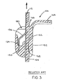
- the metal locking device of such cable ties is in the form of a cantilevered beam that is fixed at one end and extends into the strap accepting channel at the free end. Operation of such a cable tie will be described with respect to Figs. 1-3, which show operation of a cable tie device according to copending U.S. Patent Application Ser. No. (Atty. Docket No. LCB337), the subject matter of which is incorporated herein by reference in its entirety.
- the cable tie 100 of Fig. 1 includes a strap 104 (partially shown) integral with a cable tie head 102, Cable tie head 102 is formed with a locking device receiving cavity 180 and a strap accepting channel 122 having a strap entrance 168 and a strap exit 166. Strap accepting channel 122 receives the leading end 112 of strap 104, Locking device receiving cavity 180 receives a pre-formed metal locking device 136, which is formed from a corrosion resistant metal such as stainless steel
- Locking device receiving cavity 180 is provided to allow access to the anchoring region on the end wall for partial embedding of metal locking device 136 in a mounting slot 130 ofthe cable tie head 102.
- Mounting slot 130 may be preformed in an interior surface of cavity 180 or may be partially formed as a result of pressing an end 134 of locking device 136 into the interior surface of cable head 102.
- This defines a cantilever beam structure having a fixed end 134 and a free end 138 that extends into strap accepting cavity 122.
- Metal locking device receiving cavity 180 also allows for movement of locking device 136.
- Such a cable tie is sufficient for a single locking application (i.e., a single tightening operation).
- a subsequent tightening or re-threading action may be initiated to further cinch down the cable tie.
- the free end 138 of metal locking device 136 has already partially penetrated the surface of strap 104, it is possible that during these further re-thread attempts to advance the strap in the direction of exit 166, the free end will not break free from strap 104. Instead, the locking device 136 will remain partially embedded within the surface of strap 104.
- the retention force of the fixed end 134 is less than the withdrawal force necessary to break away free end 138 from strap 104, it is possible that fixed end 134 will be pulled out of slot 130. This is undesirable and results in cable tie failure as shown in Fig. 3, in which metal locking device 136 is either completely removed or sufficiently withdrawn from slot 130 to adversely affect proper cable tie functioning.
- the retention force acting on fixed end 134 to resist removal is the frictional force between fixed end 134 and slot 130. This retention force may be insufficient and is particularly problematic where the fixed end is oriented substantially parallel to the re-threading force acting on strap 104 toward exit 166, as in this example.
- a cable tie having an anchored metal locking device, comprising: a strap including a first end and a free end; a locking head secured to the first end of the strap, the locking head defining a strap accepting channel in the head having a strap entry end and a strap exit end, the locking head further including a metal locking device receiving cavity adjacent to and open toward the strap exit end of the locking head, the locking head further including a mounting slot having an inner support wall, an outer support wall and a support slot communicating the mounting slot with the receiving cavity; and a metal locking device mounted through the metal locking device receiving cavity into the support cavity, the metal locking device having a free end positioned within the strap accepting channel and a fixed end having at least one bent tang protruding outwardly from a surface of the metal locking device.
- the fixed end having the at least one bent tang is insertable through the support slot.
- the inner support surface of the mounting slot resiliently urges at least a protruding edge of the at least one bent tang against the outer support surface to anchor the metal locking device within the mounting slot and resist withdrawal of the metal locking device in a direction towards the exit end of the strap accepting channel.
- the invention also provides a method of forming a cable tie having an improved anchoring system comprising the steps of: forming a cable tie having a strap including a first end and a free end and a locking head secured to the first end of the strap, the locking head defining a strap accepting channel in the head having a strap entry end and a strap exit end, the locking head further including a metal locking device receiving cavity adjacent to and open toward the strap exit end of the locking head, the locking head further including a mounting slot having an inner support wall, an outer support wall and a support slot communicating the mounting slot with the receiving cavity; forming a metal locking device with a fixed end having at least one bent tang and a free end; initially mounting the metal locking device through the metal locking device receiving cavity into the mounting slot by inserting the fixed end through the support slot until the fixed end is urged against the inner support wall; and further inserting the metal locking device into the mounting slot and causing the inner support surface to be resiliently deformed until the at least one bent tang is substantially received within the mounting slot, at which time
- cable tie 100 with a securely anchored metal locking device according to a first embodiment will be described with reference to Figs. 4-15.
- cable tie 100 includes a locking head 102 and a strap 104.
- Cable tie 100 can be made from various materials as known in the art. Suitable materials include by way of example, nylon, polypropylene, and various fluoropolymers. Cable tie 100 can be formed in various sizes and lengths to suit a particular application as also known in the art. Obviously, desired loop tensile strength is one factor to decide when selecting sizing of the strap, locking head, locking device and other components.
- cable tie 100 is shown to have locking head 102 with a strap accepting channel 122 parallel to a strap attachment axis S and a strap that is bent at approximately 90° from strap attachment axis S
- cable tie 100 is not limited to such a configuration and may take other forms.
- the cable tie 100 may have a straight strap that continues to extend substantially along axis S.
- cable tie 100 may have a more conventional right angle locking head such as that shown in Bernard '727, that has a strap accepting channel at a right angle to strap attachment axis S.
- Strap accepting channel 122 of cable tie head 102 receives a leading end 112 of strap 104 during use.
- Strap accepting channel 122 includes a strap entry end 168 through which strap 104 is first inserted and a strap exit end 166.
- Leading end 112 is preferably tapered.
- Strap 104 may be provided with a longitudinally extending central groove 110 on the inside surface and a longitudinally extending central slot on the outside surface (unshown). Central groove 110 may taper at the end of the strap adjacent locking head 102 to form an increased width, such as by providing a V-groove 120 as best shown in Figs. 4-5.
- locking head 102 also includes a locking device receiving cavity 180.
- Locking device receiving cavity 180 provides access to the anchoring region for metal locking device 136 for partial embedding of metal locking device 136 in a mounting slot 130 of locking head 102 to define a cantilever beam structure having a fixed end 134 and a free end 138 that extends into strap accepting cavity 122.
- Metal locking device receiving cavity 180 also allows for movement of locking device 136 and includes a relief portion 182 (recessed wall) and protruding wall portion 184. Relief 182 is formed in end wall 124 at a lower part of receiving cavity 180 adjacent to the mounting slot 130.
- Mounting slot 130 also includes an outer support surface 164 and an inner support surface 162.
- Metal locking device 136 is preferably formed from a corrosion resistant metal, such as stainless steel as known in the art. While metal locking device 136 may take a conventional straight form, it is preferably bent or formed so that free end 138 is at a predetermined angle relative to fixed end 134. It is also preferable for fixed end 134 to be substantially parallel to the axis of strap accepting channel 122. This allows for easier insertion of locking device 136 into cavity 180. It also allows for a lower profile cable tie head. In any case, free end 138 extends into strap accepting channel 122 at an acute angle relative to the axis of strap accepting channel 122 facing strap exit end 166. Moreover, according to the invention, metal locking device 136 is provided with one or more bent protruding tangs 132 that project outward from the surface of fixed end 134 and act to anchor the locking device within support cavity 130 of locking head 102.
- a corrosion resistant metal such as stainless steel
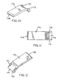
- a first preferred embodiment ofthe metal locking device 136 is shown in Figs. 10-13 and has two bent tangs 132, which are preferably formed on edge surfaces of fixed end 134 and are angled outward.
- Another embodiment of the metal locking device is shown in Figs. 14-15 and includes a single bent tang 132 projecting from an intermediate surface of the locking device 136.
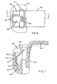
- metal locking device 136 is shown being installed through receiving cavity 180 and partially inserted into mounting slot 130.
- Fig. 9 shows the metal locking device 136 fully inserted.
- relief 182 allows the locking device to be inserted without interference with the locking device receiving cavity walls until the metal locking device 136 has been sufficiently inserted into the mounting slot 130. This keeps the metal locking device straight during installation.
- fixed end 134 penetrates through an entrance of the mounting slot 130 while the at least one bent protruding tang 132 is still located in receiving cavity 180. That is, bent tang 132 is accommodated by the relief 182 so as to align the metal locking device while not inhibiting insertion.
- the at least one bent tang 132 is forced through the entrance to mounting slot 130 as shown and the inner support surface 162 becomes displaced (i.e., pushed to the right as shown in Fig. 8).
- bent tang 132 becomes substantially within, and preferably entirely within, mounting slot 130, as shown in Fig. 9. Due to this configuration, two elements assist in retaining the metal locking device securely within the mounting slot 130.
- the urged inner support surface 162 acts to bias the locking device 136 toward the outer support surface 164. That is, the inner support surface 162 elastically relaxes in an attempt to return to its original position.
- bent tang 132 allows for a rather low resistance to insertion, due to the outwardly projecting jagged edges, tangs 132 tend to bite into the outer support surface 164 due to the biasing from the inner support surface 162.
- Forces acting to remove the free end of the strap in direction P act to further urge the sharp jagged edge of bent tang 132 against the outer support surface 164 effectively increasing the anchoring force provided by this structure.
- Forces acting to remove the metal locking device from slot 130 in direction T, as shown in Fig. 9, are resisted by the biting engagement of tang 132 against outer support surface 164.
- cantilevered metal locking device 136 is supported at a fulcrum point defined by an upper edge 142 of an inner wall of cable head 102.
- Metal locking device 136 has a free length defined from the fulcrum point to free end 138 that allows free end 138 to extend into channel 122 by a distance to sufficiently engage a strap being threaded through strap accepting channel 122 and prevent withdrawal of the strap from the channel.
- cable tie head 102 includes a locking device receiving cavity 180 as in the first embodiment.
- Locking device receiving cavity 180 receives metal locking device 136 and is provided to allow access for partial embedding of metal locking device 136 in a mounting slot 160 of cable tie head 102.
- metal locking device receiving cavity 180 also allows for movement of locking device 136 and includes a relief portion 182 (recessed wall) and protruding wall portion 184.
- metal locking device 136 of this second embodiment can be provided with one or more bent protruding tangs 132 that project outward from the surface of fixed end 134. These bent tangs may be the same as the exemplary bent tangs shown in Figs. 10-15. Thus, while it is to be noted that this second embodiment is being shown and described with the metal locking device 136 as shown in Figs. 14 and 15, neither the first or the second embodiments are limited to the locking devices shown.
- an entrance slot 152 is formed in a wall portion 150 disposed at an interior wall of mounting slot 160, Entrance slot 152 is preferably less thick than locking device 136.
- mounting slot 160 also includes an outer support surface 164 and an inner support surface 162.
- the slot 160 is preformed and is designed with inner and outer support walls that are farther apart than the width of entrance slot 152 so as to define a receiving ledge 154 on a lower side of wall portion 150 between entrance 152 and outer surface 164,
- mounting slot 160 may include an opening that extends to the exterior of cable tie head 102.
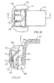
- metal locking device 136 is shown being installed through receiving cavity 180 and partially inserted into mounting slot160.
- Figs. 19-20 show the metal locking device 136 fully inserted.
- relief 182 allows the locking device to be inserted without interference with the locking device receiving cavity walls until the metal locking device 136 has been sufficiently inserted into the slot 160. This keeps the metal locking device straight during installation.
- fixed end 134 penetrates through wall 150 via entrance slot 152 of the mounting slot 160 while the at least one bent protruding tang 132 is still located in receiving cavity 180 above wall portion 150.
- bent tang 132 is accommodated by the relief 182 so as to align the metal locking device while not inhibiting insertion.
- the at least one bent tang 132 is forced through the wall 150 to mounting slot 160 as shown and the inner support surface 162 becomes displaced (i.e., pushed to the right).
- bent tang 132 becomes substantially within, and preferably entirely within, mounting slot 160, as shown in Figs. 19-20. Due to this configuration, several elements assist in retaining the metal locking device securely within the mounting slot 160.
- the urged inner support surface 162 acts to bias the locking device 136 toward the outer support surface 164. That is, the inner support surface 162 elastically relaxes in an attempt to return to its original position.
- bent tang 132 allows for a rather low resistance to insertion, due to the outwardly projecting jagged edges, tangs 132 tend to bite into the outer support surface 164 due to the biasing from the inner support surface 162. Forces acting to remove the metal locking device from slot 160 in direction T, as shown in Fig. 20 are resisted by the biting engagement of the sharp jagged edge of bent tang 132 against the outer support surface 164 and retaining ledge 154.
- FIGs. 21-23 show mounting slot 160 including an opening that extends entirely through the cable head 102 and to an external surface.
- the opening may be provided for manufacturing reasons and should be smaller than the lateral width of the locking device 136.
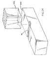
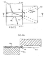
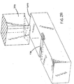
- the bent tangs 132 of the metal locking device can be formed by any known or subsequently developed method. However, two exemplary methods of forming bent tangs 132 for the preferred first embodiment (Figs. 10-13) are illustrated in Figs. 24-35.
- metal locking device 136 is placed in a punching die 300 and is acted upon by a punching ram 350. As shown, fixed end 134 overhangs die 300 by a predetermined distance corresponding to a desired location of bent tangs 132.
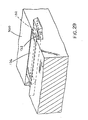
- metal locking devices 136 can be formed with the desired bent tangs 132 as shown in Fig. 28. Bent tangs 132 are better shown in the close-up of Fig. 29.
- a lower face of punching ram 350 is provided with an inverted V-shaped tooling surface.
- this is merely one example of a tang structure.
- Other suitable tang structures are contemplated.
- the metal locking device 136 is suitably formed and bent into the angled shape so that the free end is angled relative to the fixed end, such as by the method described in co-pending U.S. Patent Application Serial No. (Atty. Docket No. LCB 339), the subject matter of which is incorporated herein by reference in its entirety.
- the bent tangs may be formed after the metal locking device has been bent in the angled shape.
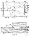
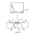
- An alternative embodiment further is provided with a support base 400, which supports the overhanging portion of metal locking device 136 that extends beyond die 300 as shown in Figs. 30-35.
- the fixed end 134 is not free floating during punching but is instead supported by base 400.
- support base 400 is provided with a support surface 402 and two tang receiving cavities 404. During punching, support surface 402 will support the overhanging section of metal locking device 136. However, the cavities 404 allow formation of the tangs 132.
- a beneficial anchoring of the locking device to the cable tie head can be achieved.
- the at least one tang provides additional resistance to metal locking device pullout to prevent failures ofthe cable ties, particularly during cable tie re-threading procedures after initial tensioning.
- the at least one tang also reduces the required depth of the anchor over that of previous systems that relied upon a straight locking device fixed end and frictional fit.
- two punching rams may be provided, with each forming one of the two bent tangs 132. In such a case, each ram could have a working face angled at an acute angle to the face of the metal locking device.
Landscapes
- Engineering & Computer Science (AREA)
- Mechanical Engineering (AREA)
- General Engineering & Computer Science (AREA)
- Supports For Pipes And Cables (AREA)
- Clamps And Clips (AREA)
- Package Frames And Binding Bands (AREA)
- Installation Of Indoor Wiring (AREA)
- Basic Packing Technique (AREA)
- Electric Cable Installation (AREA)
Abstract
Description
Claims (26)
- A cable tie having an anchored metal locking device, comprising:wherein the fixed end having the at least one bent tang is insertable into the mounting slot and upon such insertion the inner support surface of the mounting slot resiliently urges at least a protruding edge of the at least one bent tang against the outer support surface to anchor the metal locking device within said mounting slot and resist withdrawal of the metal locking device in a direction towards the exit end of the strap accepting channel.a strap including a first end and a free end;a locking head secured to the first end of the strap, the locking head defining a strap accepting channel in the head having a strap entry end and a strap exit end, the locking head further including a metal locking device receiving cavity adjacent to and open toward the strap exit end of the locking head; anda metal locking device mounted through the metal locking device receiving cavity into a mounting slot, the mounting slot having an inner support wall and outer support wall, the metal locking device having a free end positioned within the strap accepting channel and a fixed end having at least one bent tang protruding outwardly from a surface of the metal locking device,
- The cable tie of claim 1, wherein the receiving cavity includes a relief in a wall opposite the strap accepting channel.
- The cable tie of claim 2, wherein the relief accommodates the at least one bent tang to minimize interference between the wall and the at least one bent tang during insertion of the metal locking device through the receiving cavity,
- The cable tie of claim 1, wherein the fixed end of the metal locking device has a width and includes two bent tangs, one on each of two widthwise edges ofthe metal locking device.
- The cable tie of claim 1, wherein the fixed end of the metal locking device has a width and includes a single bent tang provided substantially midway along the width.
- The cable tie of claim 1, wherein the at least one bent tang is angled toward the outer support surface.
- The cable tie of claim 1, wherein the free end of the metal locking device is angled relative to the fixed end.
- The cable tie of claim 7, wherein the mounting slot and the fixed end of the metal locking device extend substantially parallel with the strap accepting channel
- The cable tie of claim 1, wherein the mounting slot includes a ledge provided on one of the inner and outer support surfaces that forms a stop that further anchors the at least one bent barb and the fixed end of the metal locking device within the support cavity.
- , A cable tie having an anchored metal locking device, comprising:wherein the fixed end having the at least one bent tang is insertable through the support slot and upon such insertion the inner support surface of the mounting slot resiliently urges at least a protruding edge of the at least one bent tang against the outer support surface to anchor the metal locking device within the mounting slot and resist withdrawal ofthe metal locking device in a direction towards the exit end of the strap accepting channel.a strap including a first end and a free end;a locking head secured to the first end of the strap, the locking head defining a strap accepting channel in the head having a strap entry end and a strap exit end, the locking head further including a metal locking device receiving cavity adjacent to and open toward the strap exit end of the locking head, the locking head further including a mounting slot having an inner support wall, an outer support wall and a support slot communicating the mounting slot with the receiving cavity; anda metal locking device mounted through the metal locking device receiving cavity into the support cavity, the metal locking device having a free end positioned within the strap accepting channel and a fixed end having at least one bent tang protruding outwardly from a surface of the metal locking device,
- The cable tie of claim 10, wherein the receiving cavity includes a relief in a wall opposite the strap accepting channel.
- The cable tie of claim 11, wherein the relief accommodates the at least one bent tang to minimize interference between the wall and the at least one bent tang during insertion of the metal locking device through the receiving cavity.
- The cable tie of claim 10, wherein the fixed end of the metal locking device has a width and includes two bent tangs, one on each of two widthwise edges of the metal locking device.
- The cable tie of claim 10, wherein the fixed end ofthe metal locking device has a width and includes a single bent tang provided substantially midway along the width.
- The cable tie of claim 10, wherein the at least one bent tang is angled toward the outer support surface.
- The cable tie of claim 10, wherein the free end of the metal locking device is angled relative to the fixed end.
- The cable tie of claim 16, wherein the mounting slot and the fixed end of the metal locking device extend substantially parallel with the strap accepting channeL
- The cable tie of claim 10, wherein the mounting slot includes a ledge provided on one of the inner and outer support surfaces that forms a stop that further anchors the at least one bent barb and the fixed end of the metal locking device within the mounting slot.
- A method of forming a cable tie having a strengthened anchoring system, comprising the steps of:forming a cable tie having a strap including a first end and a free end and a locking head secured to the first end of the strap, the locking head defining a strap accepting channel in the head having a strap entry end and a strap exit end, the locking head further including a metal locking device receiving cavity adjacent to and open toward the strap exit end of the locking head, the locking head further including a mounting slot having an inner support wall and an outer support wall;forming a metal locking device with a fixed end having at least one bent tang and a free end;initially mounting the metal locking device through the metal locking device receiving cavity into the mounting slot by inserting the fixed end into the support cavity until the fixed end is urged against the inner support wall; andfurther inserting the metal locking device into the mounting slot and causing the inner support surface to be resiliently deformed until the at least one bent tang is substantially received within the mounting slot, at which time the inner support surface urges at least an edge of the at least one bent tang against the outer support surface to securely anchor the metal locking device to the mounting slot.
- The method of claim 19, wherein the at least one bent tang is formed by punch pressing of the metal locking device.
- The method of claim 20, wherein the punch pressing forms a three-sided cut in the metal locking device to form a single bent barb.
- The method of claim 20, wherein the punch pressing forms two bent tabs extending outward from side edges of the fixed end.
- The method of claim 22, wherein the punch pressing is achieved in a single blow from a press ram at an angle normal to the face of the metal locking device.
- The method of claim 19, wherein the step of forming a receiving cavity forms a receiving cavity wall with a relief sized to accommodate the at least one bent tang and minimize interference during metal locking device insertion.
- The method of claim 19, further comprising a step of bending the free end of the metal locking device to be angled relative to the fixed end.
- The method of claim 19, wherein the step of forming the cable tie head forms the strap accepting channel and the mounting slot to be substantially parallel.
Applications Claiming Priority (2)
| Application Number | Priority Date | Filing Date | Title |
|---|---|---|---|
| US09/855,262 US6530126B2 (en) | 2001-05-15 | 2001-05-15 | Low thread force cable tie with anchored locking device |
| US855262 | 2001-05-15 |
Publications (2)
| Publication Number | Publication Date |
|---|---|
| EP1258432A1 true EP1258432A1 (en) | 2002-11-20 |
| EP1258432B1 EP1258432B1 (en) | 2004-12-22 |
Family
ID=25320784
Family Applications (1)
| Application Number | Title | Priority Date | Filing Date |
|---|---|---|---|
| EP02253457A Expired - Lifetime EP1258432B1 (en) | 2001-05-15 | 2002-05-15 | Low thread force cable tie with locking device |
Country Status (5)
| Country | Link |
|---|---|
| US (2) | US6530126B2 (en) |
| EP (1) | EP1258432B1 (en) |
| JP (1) | JP4083465B2 (en) |
| CN (1) | CN1264731C (en) |
| DE (1) | DE60202318T2 (en) |
Cited By (1)
| Publication number | Priority date | Publication date | Assignee | Title |
|---|---|---|---|---|
| ITTO20100949A1 (en) * | 2010-11-30 | 2012-05-31 | Illinois Tool Works | WIRING HARNESS / FIXING AND METHOD FOR THE REALIZATION OF A HARNESS / FIXING CLAMP |
Families Citing this family (29)
| Publication number | Priority date | Publication date | Assignee | Title |
|---|---|---|---|---|
| JPH06140143A (en) * | 1992-10-27 | 1994-05-20 | Uchino:Kk | Heating device for melting |
| USD530600S1 (en) | 2004-10-18 | 2006-10-24 | Panduit Corp. | Cable tie |
| US8486106B2 (en) * | 2004-10-21 | 2013-07-16 | Piper Medical, Inc. | Disposable digital tourniquets and related methods of providing occlusion pressures to a single digit during surgical procedures |
| US7779515B2 (en) * | 2005-05-13 | 2010-08-24 | Panduit Corp. | Two-piece cable tie suitable for use in an automated cable tie installation tool |
| JP4968779B2 (en) * | 2006-12-08 | 2012-07-04 | 北川工業株式会社 | Sealing tool |
| US7866005B2 (en) * | 2008-01-09 | 2011-01-11 | Panduit Corp. | Elastomeric releasable cable tie |
| EP2255411B1 (en) | 2008-02-21 | 2015-07-01 | Melni LLC | Electrical connector |
| US8066525B2 (en) * | 2008-02-21 | 2011-11-29 | Melni Mark L | Electrical connectors and methods of manufacturing and using same |
| DE202008006986U1 (en) | 2008-05-23 | 2009-10-01 | Elkamet Kunststofftechnik Gmbh | Profile element for connecting a vehicle window with a water tank |
| US8281461B2 (en) * | 2009-06-05 | 2012-10-09 | Hellermanntyton Corporation | Button head tie |
| EP2283806A1 (en) | 2009-08-11 | 2011-02-16 | DSM IP Assets B.V. | Carnosol for hair and skin care |
| KR101215224B1 (en) * | 2010-07-12 | 2012-12-24 | 다산이노씨엠 주식회사 | Level tie for concrete pouring |
| US9334091B2 (en) | 2010-10-11 | 2016-05-10 | Ideal Industries, Inc. | Cable lacing tie devices and methods of using the same |
| CA2813143C (en) | 2010-10-11 | 2019-05-28 | Ideal Industries, Inc. | Cable lacing tie devices and methods of using the same |
| US9015906B2 (en) | 2011-08-03 | 2015-04-28 | Thomas & Betts International, Inc. | Cable tie with improved pawl |
| RU2667588C2 (en) * | 2013-03-15 | 2018-09-21 | Идеал Индастриз, Инк. | Cable lacing tie devices and methods of using the same |
| US20150267844A1 (en) | 2014-03-24 | 2015-09-24 | Ideal Industries, Inc. | Cable lacing tie devices and methods of using the same |
| SE538496C2 (en) * | 2014-07-11 | 2016-08-09 | Resorbable Devices Ab | Cable tie based medical device |
| CN109051313A (en) * | 2018-09-27 | 2018-12-21 | 宏泰电器有限公司 | Split type tie |
| CN110897675B (en) * | 2019-03-18 | 2024-10-11 | 温州益宏医疗科技有限公司 | Connecting structure of elastic belt and lock tongue of tourniquet with lock catch structure |
| USD878151S1 (en) | 2019-05-06 | 2020-03-17 | Natasha Tomlinson | Wine glass stem |
| CN111422497B (en) * | 2020-05-08 | 2025-04-15 | 郑明维 | Cable tie with self-locking structure |
| USD913150S1 (en) | 2020-07-30 | 2021-03-16 | Natasha Tomlinson | Article of embellishment |
| SE545229C2 (en) * | 2021-04-07 | 2023-05-30 | Evlr Int Ab | Cable tie |
| US11738922B2 (en) | 2021-06-22 | 2023-08-29 | HellermanTyton Corporation | Pawl-latching devices |
| EP4183699A1 (en) | 2021-10-21 | 2023-05-24 | Hellermann Tyton GmbH | Automatic bundling tool device for bundling a bundling good by means of differently shaped one-piece-ties |
| US12253197B2 (en) | 2022-06-21 | 2025-03-18 | Hellermanntyton Corporation | Bi-directional buttonhead ties |
| US12365524B2 (en) * | 2022-07-07 | 2025-07-22 | Abb Schweiz Ag | Cable bundling system |
| CN115783896B (en) * | 2022-12-16 | 2025-07-29 | 台州市新大陆电子科技有限公司 | Strapping machine with linkage switch |
Citations (3)
| Publication number | Priority date | Publication date | Assignee | Title |
|---|---|---|---|---|
| US3588961A (en) * | 1969-09-18 | 1971-06-29 | George Farago | Adjustable self-locking bundling straps |
| US3875618A (en) * | 1973-12-10 | 1975-04-08 | Fastway Fasteners | Bundling tie |
| EP0919756A2 (en) * | 1997-12-01 | 1999-06-02 | Thomas & Betts International, Inc. | Improved cable tie having a locking head and a separate strap |
Family Cites Families (23)
| Publication number | Priority date | Publication date | Assignee | Title |
|---|---|---|---|---|
| US3186047A (en) | 1962-08-14 | 1965-06-01 | Thomas & Betts Corp | Self clinching bundling strap |
| DE1275650B (en) | 1967-03-03 | 1968-08-22 | Hellermann Gmbh P | Cable tie device |
| US3408699A (en) | 1967-08-07 | 1968-11-05 | Thomas & Betts Corp | Bundling strap |
| US3486200A (en) | 1968-07-23 | 1969-12-30 | Emil H Orenick | Cable strap |
| US3457598A (en) | 1968-08-09 | 1969-07-29 | Thomas & Betts Corp | Self-clinching bundling strap |
| US3488813A (en) | 1968-08-22 | 1970-01-13 | Thomas & Betts Corp | Bundling strap |
| US4875647A (en) | 1987-04-24 | 1989-10-24 | Daiwa Kasei Kogyo Kabushiki Kausha | Cable tie |
| CA2047945C (en) | 1990-08-02 | 1995-04-04 | William A. Fortsch | Cable tie having improved locking barb |
| US5121524A (en) * | 1991-04-26 | 1992-06-16 | Panduit Corp. | Cable tie |
| US5317787B1 (en) | 1992-10-01 | 1995-11-28 | Thomas & Betts Corp | Cable tie having improved tail gripping and holding feature |
| EP0665807B1 (en) | 1993-08-31 | 1999-11-10 | Panduit Corp. | Low thread force cable tie |
| GB2285475B (en) | 1994-01-07 | 1997-09-24 | Thomas & Betts Corp | Improvements in cable ties |
| US5513421A (en) * | 1994-04-15 | 1996-05-07 | Thomas & Betts Corporation | Cable tie having an improved strap locking device |
| CA2146828A1 (en) | 1994-04-15 | 1995-10-16 | Peter M. Wells, Jr. | Cable tie having an improved strap body |
| USD372665S (en) | 1994-12-30 | 1996-08-13 | Sooki Kim | Cable tie |
| US5621949A (en) * | 1995-04-07 | 1997-04-22 | Thomas & Betts Corproation | Barbed cable tie |
| GB2308153B (en) | 1995-12-13 | 2000-08-16 | Bowthorpe Plc | Parallel entry tie |
| US6279203B1 (en) * | 1996-02-06 | 2001-08-28 | Panduit Corp | Two-piece cable tie with coined locking wedge |
| US5774944A (en) | 1996-07-26 | 1998-07-07 | Choi; Woncheol | Band cable easily released from coupling state |
| US5815891A (en) | 1997-02-06 | 1998-10-06 | Thomas & Betts Corporation | Cable tie with bent barb |
| US5781975A (en) | 1997-03-12 | 1998-07-21 | Thomas & Betts Corporation | Flexible platform for cable tie barb |
| US5745957A (en) | 1997-03-26 | 1998-05-05 | Thomas & Betts Corporation | In-line cable tie |
| US5881435A (en) * | 1998-06-30 | 1999-03-16 | Jermyn, Jr.; Richard A. | Tie strap device having locking head with line of weakness |
-
2001
- 2001-05-15 US US09/855,262 patent/US6530126B2/en not_active Expired - Fee Related
-
2002
- 2002-05-15 EP EP02253457A patent/EP1258432B1/en not_active Expired - Lifetime
- 2002-05-15 CN CNB021215022A patent/CN1264731C/en not_active Expired - Fee Related
- 2002-05-15 JP JP2002139665A patent/JP4083465B2/en not_active Expired - Fee Related
- 2002-05-15 DE DE60202318T patent/DE60202318T2/en not_active Expired - Fee Related
-
2003
- 2003-01-15 US US10/342,830 patent/US6584652B2/en not_active Expired - Fee Related
Patent Citations (3)
| Publication number | Priority date | Publication date | Assignee | Title |
|---|---|---|---|---|
| US3588961A (en) * | 1969-09-18 | 1971-06-29 | George Farago | Adjustable self-locking bundling straps |
| US3875618A (en) * | 1973-12-10 | 1975-04-08 | Fastway Fasteners | Bundling tie |
| EP0919756A2 (en) * | 1997-12-01 | 1999-06-02 | Thomas & Betts International, Inc. | Improved cable tie having a locking head and a separate strap |
Cited By (2)
| Publication number | Priority date | Publication date | Assignee | Title |
|---|---|---|---|---|
| ITTO20100949A1 (en) * | 2010-11-30 | 2012-05-31 | Illinois Tool Works | WIRING HARNESS / FIXING AND METHOD FOR THE REALIZATION OF A HARNESS / FIXING CLAMP |
| WO2012075034A1 (en) * | 2010-11-30 | 2012-06-07 | Illinois Tool Works Inc. | Cable tie and method to produce a cable tie |
Also Published As
| Publication number | Publication date |
|---|---|
| DE60202318D1 (en) | 2005-01-27 |
| US20020170151A1 (en) | 2002-11-21 |
| DE60202318T2 (en) | 2005-12-08 |
| US20030101543A1 (en) | 2003-06-05 |
| CN1390752A (en) | 2003-01-15 |
| JP2003102122A (en) | 2003-04-04 |
| US6530126B2 (en) | 2003-03-11 |
| US6584652B2 (en) | 2003-07-01 |
| JP4083465B2 (en) | 2008-04-30 |
| CN1264731C (en) | 2006-07-19 |
| EP1258432B1 (en) | 2004-12-22 |
Similar Documents
| Publication | Publication Date | Title |
|---|---|---|
| EP1258432B1 (en) | Low thread force cable tie with locking device | |
| EP1258434A1 (en) | Low profile cable tie with pre-bent strap | |
| EP1258664B1 (en) | Cable tie with locking device that pierces strap | |
| US5820176A (en) | Security seal and lock | |
| US6473942B1 (en) | Cable tie with thread force reducing structure | |
| US8424166B2 (en) | Dual locking band clamp and method of forming the same | |
| US6279203B1 (en) | Two-piece cable tie with coined locking wedge | |
| JPH11503216A (en) | Improved barbed cable tie | |
| US6484367B1 (en) | Cable tie with bent locking device and method of manufacture therefor | |
| US7721912B2 (en) | Hinge assembly using substantially straight hinge pin | |
| AU2019429303B2 (en) | Sealing band | |
| JP5191874B2 (en) | Cow nose ring | |
| JP2002184504A (en) | Terminal metal fitting and connector |
Legal Events
| Date | Code | Title | Description |
|---|---|---|---|
| PUAI | Public reference made under article 153(3) epc to a published international application that has entered the european phase |
Free format text: ORIGINAL CODE: 0009012 |
|
| AK | Designated contracting states |
Kind code of ref document: A1 Designated state(s): AT BE CH CY DE DK ES FI FR GB GR IE IT LI LU MC NL PT SE TR |
|
| AX | Request for extension of the european patent |
Free format text: AL;LT;LV;MK;RO;SI |
|
| 17P | Request for examination filed |
Effective date: 20030410 |
|
| 17Q | First examination report despatched |
Effective date: 20030610 |
|
| AKX | Designation fees paid |
Designated state(s): DE FR GB IT |
|
| GRAP | Despatch of communication of intention to grant a patent |
Free format text: ORIGINAL CODE: EPIDOSNIGR1 |
|
| GRAS | Grant fee paid |
Free format text: ORIGINAL CODE: EPIDOSNIGR3 |
|
| GRAA | (expected) grant |
Free format text: ORIGINAL CODE: 0009210 |
|
| AK | Designated contracting states |
Kind code of ref document: B1 Designated state(s): DE FR GB IT |
|
| REG | Reference to a national code |
Ref country code: GB Ref legal event code: FG4D |
|
| REG | Reference to a national code |
Ref country code: IE Ref legal event code: FG4D |
|
| REF | Corresponds to: |
Ref document number: 60202318 Country of ref document: DE Date of ref document: 20050127 Kind code of ref document: P |
|
| ET | Fr: translation filed | ||
| PLBE | No opposition filed within time limit |
Free format text: ORIGINAL CODE: 0009261 |
|
| STAA | Information on the status of an ep patent application or granted ep patent |
Free format text: STATUS: NO OPPOSITION FILED WITHIN TIME LIMIT |
|
| 26N | No opposition filed |
Effective date: 20050923 |
|
| PGFP | Annual fee paid to national office [announced via postgrant information from national office to epo] |
Ref country code: DE Payment date: 20090511 Year of fee payment: 8 Ref country code: FR Payment date: 20090515 Year of fee payment: 8 Ref country code: IT Payment date: 20090519 Year of fee payment: 8 |
|
| PGFP | Annual fee paid to national office [announced via postgrant information from national office to epo] |
Ref country code: GB Payment date: 20090513 Year of fee payment: 8 |
|
| GBPC | Gb: european patent ceased through non-payment of renewal fee |
Effective date: 20100515 |
|
| REG | Reference to a national code |
Ref country code: FR Ref legal event code: ST Effective date: 20110131 |
|
| PG25 | Lapsed in a contracting state [announced via postgrant information from national office to epo] |
Ref country code: IT Free format text: LAPSE BECAUSE OF NON-PAYMENT OF DUE FEES Effective date: 20100515 |
|
| PG25 | Lapsed in a contracting state [announced via postgrant information from national office to epo] |
Ref country code: DE Free format text: LAPSE BECAUSE OF NON-PAYMENT OF DUE FEES Effective date: 20101201 |
|
| PG25 | Lapsed in a contracting state [announced via postgrant information from national office to epo] |
Ref country code: FR Free format text: LAPSE BECAUSE OF NON-PAYMENT OF DUE FEES Effective date: 20100531 |
|
| PG25 | Lapsed in a contracting state [announced via postgrant information from national office to epo] |
Ref country code: GB Free format text: LAPSE BECAUSE OF NON-PAYMENT OF DUE FEES Effective date: 20100515 |