BACKGROUND OF THE INVENTION
1. Field of the Invention
This invention relates to a thermal transfer line
printer that is suitably used for forming an intermediate
transfer type image in which ink of a multi-color ink
sheet is transferred on an intermediate transfer sheet
by means of a line thermal head to form a primary image
and the primary image is retransferred on a transfer
medium to form an image on the transfer medium.
2. Description of the Related Art
Heretofore, the intermediate transfer type
thermal transfer line printer for forming an image on
a transfer medium by means of a method in which ink of
a multi-color ink film is transferred on an intermediate
transfer medium by use of a line thermal head to form
a primary image and the primary image is retransferred
on a transfer medium by use of a retransfer means has
been used widely as an output apparatus of a computer
or ward processor. The reasons are that a high quality
printed image can be formed easily on various transfer
media such as CD, CD-R, MO, DVD, and various cards in
addition to regular paper and that the intermediate
transfer type thermal transfer line printer is operated
with low noise, available at low cost, and needs less
maintenance.
A conventional thermal transfer line printer as
described hereinabove operates as described hereunder.
A line thermal head is brought into down-state in which
the line thermal head is brought into contact with a
platen roller with interposition of an ink sheet and an
intermediate transfer sheet that are formed in the
configuration of long sheet in this order in a primary
image forming section. Heating elements of the line
thermal head are heated selectively based on the printing
information with feeding the ink sheet and the
intermediate transfer sheet in this state to thereby melt
or sublimate the ink carried on the ink sheet so that
the ink is transferred on the intermediate transfer sheet,
and a reverse image that is served as the intermediate
image for one page, namely one picture, is formed on the
intermediate transfer sheet. Thereafter, the
intermediate transfer sheet is moved and the primary
image formed on the intermediate transfer sheet is
concomitantly moved to the position just before the
retransfer section, and then the primary image is
registered with a transfer medium with aid of the register
mark formed on the intermediate transfer sheet. Then,
the primary image formed on the intermediate transfer
sheet is melted or sublimated by applying heat and
pressure of retransfer means comprising a heating roller
in a retransfer section, and the primary image is
retransferred and fixed on the transfer medium to thereby
form a desired image on the transfer medium.
At that time, in the case where a monochrome image
of one color is formed on a transfer medium, one pass
is enough for forming an image.
On the other hand, in the case where a multi-color
image is formed on a transfer medium, a multi-color
intermediate image is formed by means of so-called
swing-back technique as described hereunder. A
multi-color ink sheet on which a plurality of color ink
regions are arranged so that different colors are
repeated adjacently in the longitudinal direction is used
as an ink sheet. At first, a reverse image of the first
color ink that is carried on the multi-color ink sheet
is formed on an intermediate transfer sheet. Then, a
line thermal head is brought into head-up state in which
the line thermal head is being separated from a platen,
and the intermediate transfer sheet is moved reversely
to the transfer preparation position in this state. The
reverse image formed with the first color ink is returned
to the transfer position for start alignment, and a
reverse image of the next color is transferred on the
reverse image of the first color one on the other.
In detail, in the case where a full-color image
is formed, a multi-color ink sheet on which a plurality
of ink regions, each of which consists of four colors,
for example, K (black), Y (yellow), M (magenta), and C
(cyan) are arranged so that the different colors are
repeated adjacently in the longitudinal direction and
which has color-discrimination marks on the boundary
between different ink regions is used as an ink sheet.
More in detail, at first, a K-color reverse image
for one page picture is formed on an intermediate transfer
sheet by use of a K-color ink region on the multi-color
ink sheet. Next, the intermediate transfer sheet that
has been moved during the primary image forming operation
is moved in the reverse direction to the transfer
preparation position to align the K-color reverse image
formed on the intermediate transfer sheet, and a Y-color
ink region that is positioned adjacent to the K-color
ink region of the multicolor ink sheet is aligned. With
the use of the Y-color ink region in the multi-color sheet,
a Y-color reverse image for one page picture is formed
over the K-color reverse image for one page picture that
has been formed on the intermediate transfer sheet.
Similarly, reverse images of an M-color ink region and
a C-color ink region are formed on the intermediate
transfer sheet in this order to thereby form a full-color
intermediate image for one page picture on the
intermediate transfer sheet.
The conventional register mark that has been
formed on an intermediate transfer sheet previously or
is formed simultaneously when a primary image is formed
on an intermediate transfer sheet.
Furthermore, the intermediate transfer sheet is
wound between the intermediate transfer sheet feeding
roller and the intermediate transfer sheet winding roller.
The intermediate transfer sheet winding roller is rotated
by means of the driving force of the intermediate transfer
sheet feeding motor when a reverse image is formed, and
the intermediate transfer sheet is sent out from the
intermediate transfer sheet feeding roller and wound on
the intermediate transfer sheet winding roller.
Furthermore, in the case where the intermediate transfer
sheet is moved back to the printing preparation position
to form a full-color image, the intermediate transfer
sheet feeding roller is rotated reversely by means of
the driving force of the intermediate transfer sheet
feeding motor. Thereby, the intermediate transfer sheet
is moved in the reverse direction toward the intermediate
transfer sheet feeding roller side from the intermediate
transfer sheet winding roller side.
As the result of the above operation, the length
of the intermediate transfer sheet wound on the
intermediate transfer sheet feeding roller decreases
with consumption of the intermediate transfer sheet to
result in the reduced outside diameter of the
intermediate transfer sheet feeding roller, and on the
other hand the length of the intermediate transfer sheet
wound on the intermediate transfer sheet winding roller
increases to result in the increased outside diameter
of the intermediate transfer sheet winding roller.
However, in the case of the abovementioned
conventional thermal transfer line printer, the
intermediate transfer sheet tension changes due to the
change of the outside diameter of the intermediate
transfer sheet feeding roller and the intermediate
transfer sheet winding roller that is caused
concomitantly with consumption of the intermediate
transfer sheet, and the change causes the problem.
The change of the intermediate transfer sheet
tension causes the change of moving length of the
intermediate transfer sheet when the intermediate
transfer sheet is moved reversely to the printing
preparation position for forming a full-color image, and
the change of the moving length causes positional
deviation when the reverse image is transferred on the
intermediate transfer sheet to result in the poor picture
quality of the image printed on a transfer medium.
To solve the abovementioned problem, a thermal
transfer line printer that is capable of maintaining the
intermediate transfer sheet tension constant has been
expected to be developed.
SUMMARY OF THE INVENTION
The present invention has been accomplished in
view of the abovementioned problem, and it is the object
of the present invention to provide a thermal transfer
line printer that is capable of maintaining the
intermediate transfer sheet tension constant with the
simple structure.
To achieve the abovementioned object, a thermal
transfer line printer in accordance with the present
invention is characterized in that the thermal transfer
line printer has a tension roller disposed so as to face
to a moving path of the intermediate transfer sheet, a
rotatable tension roller support frame that supports the
tension roller rotatably and presses the tension roller
against the intermediate transfer sheet, tension roller
position detection means that detects a position of the
tension roller, and a controller that controls operation
of an intermediate transfer sheet feeding motor for
feeding at least the intermediate transfer sheet, the
tension roller position detection means is provided with
a detector disposed on the tension roller support frame
and a sensor that detects the position of the detector,
and the controller, when feeding the intermediate
transfer sheet, controls the intermediate transfer sheet
feeding motor so as to maintain the detector in a
detection range of the sensor.
At that time, the tension roller is provided
preferably on any one of both sides of the primary image
forming section, and more preferably the tension roller
is provided on both sides of the primary image forming
section.
By employing the abovementioned structure, the
intermediate transfer sheet tension can be maintained
constant with the simple structure.
An embodiment of the present invention, will now
be described, by way of example, with reference to the
accompanying diagrammatic drawings, in which:
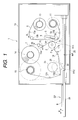
FIG. 1 to FIG. 4 show an embodiment of a thermal
transfer line printer in accordance with the present
invention. FIG. 1 is a partial front view showing the
whole structure of an embodiment of a thermal transfer
line printer in accordance with the present invention,
FIG. 2 is a partial perspective view of FIG. 1, FIG. 3
is a back view of FIG. 2, and FIG. 4 is a block diagram
showing the partial structure of a controller.
An exemplary thermal transfer line printer of
the present embodiment is served to form a full-color
image by use of a multi-color ink sheet on which four-color
ink regions formed of four color inks, namely K, Y, M,
and C, are arranged repeatedly in this order so that the
different colors are located adjacently in the
longitudinal direction and on which the color-discrimination
mark is formed on the boundary between
respective ink regions.
As shown in FIG. 1, a platen roller 2 is provided
rotatably in a printer body 1a of the thermal transfer
line printer of the present embodiment. The platen
roller 2 is rotatably formed by receiving transmission
of driving force of a platen driving motor 3 (FIG. 4)
such as a stepping motor. The platen driving motor 3 is
connected electrically to a controller 4 (FIG. 4) that
is served to control the operation of other sections
described hereinafter, and the stopping, starting,
rotation speed, and rotation direction are controlled
based on the control command sent out from the controller
4.
A line thermal head 5 that can be brought into
contact with and detached from the platen roller 2 is
provided on the left side of the platen roller 2 shown
on the left in FIG. 1 so that a printing surface 5a faces
to the outer peripheral surface of the platen roller 2.
The line thermal head 5 extends in the direction parallel
to the axial direction of the platen roller 2.
Furthermore, on the printing surface 5a of the line
thermal head 5, a plurality of heating elements (not shown
in the drawings) are arranged over the length equivalent
to the size of the multi-color ink sheet 6 and the size
of the intermediate transfer sheet 7 in the direction
orthogonal to the moving direction of the multiple-color
ink sheet 6 shown by the arrow A shown in FIG. 1 and in
the direction orthogonal to the moving direction of the
intermediate transfer sheet 7 shown by the arrow B shown
in FIG. 1. The length of a heating element is formed so
as to be longer than the size in the direction that is
orthogonal to the moving direction of an image formed
on the transfer medium 8. Furthermore, the line thermal
head 5 is connected electrically to the controller 4 (FIG.
4) that will be described hereinafter, and each heating
element is heated selectively based on the control
command sent out from the controller 4 according to the
printing information.
The line thermal head 5 is fabricated so as to
be positioned at least at two positions selectively by
means of a head contact ON/OFF mechanism, not shown in
the drawings, that is operated by means of driving force
of the head contact ON/OFF motor 9 (FIG. 4). One position
is the head-up position in which the head is positioned
at the up-position, that is, the head is separated from
the platen roller 2 as shown with a solid line in FIG.
1, and the other position is the head-down position in
which the head is positioned at the down-position, that
is, the head is in contact with the platen roller 2 with
pressure as shown with a broken line in FIG. 1. The head
contact ON/OFF motor 9 is connected electrically to the
controller 4 (FIG. 4) that is served to control the
operation of other sections that will be described
hereinafter, and the position of the line thermal head
5 is controlled based on the control command sent out
from the controller 4 at the desired timing.
The multi-color ink sheet 6 and the intermediate
transfer sheet 7 are supplied in the order from the line
thermal head 5 side between the platen roller 2 and the
line thermal head 5.
The multi-color ink sheet 6 is wound between the
ink sheet feeding roller 10 disposed in the printer body
1a near the left portion of FIG. 1 and an ink sheet winding
roller 11 disposed under the ink sheet feeding roller
10. The multi-color ink sheet 6 is sent out from the ink
sheet feeding roller 10 by at least rotating the ink sheet
winding roller 11 by means of driving force of an ink
sheet feeding motor 12 (FIG. 4) comprising a control motor
such as stepping motor, and is wound on the ink sheet
winding roller 11. Furthermore, the moving path and
moving direction of the multi-color ink sheet 6 to be
sent out by the ink sheet feeding roller 10 are controlled
so as to be wound on the ink sheet winding roller 11
through four guide rollers disposed rotatably in the
printer body 1a in the order from 13a, to 13b, 13c, and
13d as shown with an arrow A in FIG. 1. Furthermore, the
moving path of the multi-color ink sheet 6 is formed so
that the back surface side on which the ink region (not
shown in the drawing) is not formed faces to the line
thermal head 5. Furthermore, the ink sheet feeding motor
12 is connected electrically to the controller 4 (FIG.
4) for controlling the operation of other sections that
will be described hereinabove, and the stop, start, and
rotation speed of the ink sheet feeding motor 12 is
controlled based on the control command supplied from
the controller 4.
On the other hand, the intermediate transfer
sheet 7 is wound between an intermediate transfer sheet
feeding roller 14 disposed at the place located above
and slightly right from the platen roller 2 in the printer
body 1a and an intermediate transfer sheet winding roller
15 disposed near the upper right corner in FIG. 1 in the
printer body 1a. Furthermore, at least the intermediate
transfer sheet 7 is sent out from the intermediate
transfer sheet feeding roller 14 by rotating the
intermediate transfer sheet winding roller 15 by means
of driving force of an intermediate transfer sheet
feeding motor 16 (FIG. 4) , and wound on the intermediate
transfer sheet winding roller 15.
Furthermore, the intermediate transfer sheet 7
sent out from the intermediate transfer sheet feeding
roller 14 is controlled so as to be moved as described
hereunder. As shown with an arrow B in FIG. 1, the
intermediate transfer sheet 7 is moved through a guide
roller 13e and a tension roller 17a rotatably disposed
in the printer body 1a in this order, moved along the
outside surface of the platen roller 2, then moved through
a tension roller 17b that is disposed rotatably in the
printer body 1a and three guide rollers 13f, 13g, and
13h in this order, and then wound on the intermediate
transfer sheet winding roller 15.
The two tension rollers 17a and 17b disposed on
both sides of the platen roller 2, which are located so
as to face to the moving path of the intermediate transfer
sheet 7, are served to maintain the tension of the
intermediate transfer sheet 7 constant. As shown in FIG.
2, the tension roller 17a disposed above the overhung
platen roller 2 is supported rotatably by a pair of
tension roller support frames 18aa and 18ab.
Furthermore, the tension roller 17b disposed on the left
side of the platen roller 2 is supported at both ends
rotatably by a pair of tension roller support frames 18ba
and 18bb. The respective tension roller support frames
18aa, 18ab, 18ba, and 18bb are supported rotatably on
a mounting frame (not shown in the drawings), and the
tension roller support frames 18aa and 18ab are rotatable
round the rotation center Ra shown on the upper portion
of FIG. 2 with a dashed line. Furthermore, the tension
roller support frames 18ba and 18bb shown on the lower
portion of FIG. 2 are rotatable round the rotation center
Rb shown on the lower portion of FIG. 2 with a dashed
line. Furthermore, the tension roller support frame 18a
shown on the upper portion of FIG. 2 and the tension roller
support frame 18bb shown on the lower portion of FIG.
2 are linked together with a link plate (not shown in
the drawings) , and the respective tension roller support
frames 18aa, 18ab, 18ba, and 18bb are formed so as to
operate sequentially. Furthermore, the one end of a
compression coil spring 19 is fixed to the tension roller
support frame 18bb shown on the lower portion of FIG.
2, and the other end of the compression coil spring is
fixed to a mounting frame (not shown in the drawings).
Thereby, the tension support frames 18ba and 18bb shown
on the lower portion of FIG. 2 are pressed in the
anticlockwise direction round the rotation center Rb,
and on the other hand the tension roller support frames
18aa and 18ab shown on the upper portion of FIG. 2 are
pressed in the clockwise direction round the rotation
center Ra. In other words, the tension roller support
frames 18aa, 18ab, 18ba, and 18bb are structured so as
to press the tension rollers 17a and 17b toward the
intermediate transfer sheet 7.
The tension roller 17a is in contact with the
intermediate transfer sheet 7 so as to press the
intermediate transfer sheet 7 from the right side to the
left side in FIG. 1 as shown with an arrow C in FIG. 1.
On the other hand, the tension roller 17b disposed on
the left side of the platen roller 2 is in contact with
the intermediate transfer sheet 7 so as to press the
intermediate transfer sheet 7 from the under position
toward upper left direction in FIG. 1 as shown with an
arrow D in FIG. 1.
In the case of the structure that the
intermediate transfer sheet 7 is not moved reversely,
only the tension roller 17b disposed on the winding side,
namely left side of the platen roller 2, may be provided.
As shown in FIG. 2, the approximately flat-shaped
base ends of the detectors 20a and 20b are fixed
respectively to the two tension roller support frames
18ab and 18bb shown on the upper right portion of FIG.
2 and on the lower right portion of FIG. 2 respectively.
Sensors 21a and 21b comprising optical sensors (photo
interrupter) fixed to a mounting frame (not shown in the
drawings) are disposed on the end portions of these
detectors 20a and 20b, and the detectors 20a and 20b shut
off or open the sensors 21a and 21b to thereby detect
the position of the detector 20a and 20b. These sensors
21a and 21b are connected electrically to the controller
4 (FIG. 4) for controlling the operation of other sections
that will be described hereinafter, and the detection
signal that indicates shutting off or opening of the
sensors 21a and 21b by the detectors 20a and 20b is
supplied to the controller 4.
The abovementioned sensor 21a and 21b and the
detectors 20a and 20b constitute tension roller position
detection means 22 for detecting the position of the
tension rollers 17a and 17b of the present embodiment.
The detection of the tension rollers 17a and 17b position
will be described hereinafter.
The description will return to FIG. 1. The
moving path is formed so that the intermediate transfer
sheet 7 is brought into contact with the multi-color ink
sheet 6 at the contact position with the platen roller
2, and the intermediate transfer sheet 7 faces to the
ink region of the multi-color ink sheet 6 at the contact
position.
As shown in FIG. 3, the intermediate transfer
sheet feeding roller 14 and the intermediate transfer
sheet winding roller 15 are formed rotatably so as to
be rotated by means of driving force of intermediate
transfer sheet moving motor 16 comprising a servo motor
or pulse motor that is rotatable reversely. In detail,
the driving force of the intermediate transfer sheet
feeding motor 16 is formed so as to be transmitted
selectively to any one of an intermediate transfer sheet
feeding roller driving gear 14a and an intermediate
transfer sheet winding roller driving gear 15b through
a rockable gear 23a disposed on the output end of a gear
train 23. The driving force of the intermediate transfer
sheet feeding motor 16 drives the intermediate transfer
sheet winding roller driving gear 15a so as to be rotated
to thereby send out the intermediate transfer sheet 7
from the intermediate transfer sheet feeding roller 14,
and the intermediate transfer sheet 7 is wound on the
intermediate transfer sheet winding roller 15. On the
other hand, when the intermediate transfer sheet feeding
roller driving gear 14a is rotated reversely by means
of the driving force of the intermediate transfer sheet
feeding motor 16, the intermediate transfer sheet 7 is
moved reversely from the intermediate transfer sheet
winding roller 15 side to the intermediate transfer sheet
feeding roller 14 side. Otherwise, the intermediate
transfer sheet feeding roller driving gear 14a and the
intermediate transfer sheet winding roller driving gear
15a may be driven by separate intermediate transfer sheet
feeding motors 16 independently.
The intermediate transfer sheet 7 used in the
present embodiment comprises a long transparent resin
film or resin sheet consisting of
polyethyleneterephthalate (PET) material or such film
or sheet on which some material is coated for easy
subsequent retransfer of an intermediate image.
Furthermore, the size of the intermediate transfer sheet
7 in the width direction orthogonal to the moving
direction shown with an arrow B in FIG. 1 is approximately
equal to the size of the multi-color ink sheet 6 in the
width direction. Various materials such as thin papers
and resin films may be used as the intermediate transfer
sheet 7 as long as ink can be transferred from the
multi-color ink sheet 6 and the ink that has been
transferred on the intermediate transfer sheet 7 can be
retransferred on a transfer medium 8.
The abovementioned platen roller 2 and the line
thermal head 5 constitute a primary image forming section
24 that is served for transferring the ink of the
multi-color ink sheet 6 of the present embodiment on the
intermediate transfer sheet 7 to form an intermediate
image (not shown in the drawing) comprising a reverse
image on the intermediate transfer sheet 7.
Furthermore, in the head-down state shown with
a broken line shown in FIG. 1 in which the line thermal
head 5 is in contact with the platen roller 2 with a
certain contact force, the contact position between the
thermal head 5 and the platen roller 2 is the intermediate
transfer position PP1 where the ink of the multi-color
ink sheet 6 is transferred on the intermediate transfer
sheet 7 to thereby form a primary image comprising a
reverse image on the intermediate transfer sheet 7.
On the downstream side in the moving direction
of the intermediate transfer sheet 7 from the primary
image forming section 18, more in detail between two guide
rollers 13f and 13g disposed on the left side from the
position of the platen roller 2 in FIG. 1, a heating roller
25 that is served as the retransfer means is disposed
so as to face to the moving path of the intermediate
transfer sheet 7 from the above. The heating roller 25
is rotated by means of transmission of the driving force
of a heating roller driving motor 26 (FIG. 4) such as
a stepping motor. Furthermore, the heating roller 25 is
structured so as to be positioned selectively at least
two positions, namely a separate position in which the
heating roller 25 is apart from the intermediate transfer
sheet 7 as shown with a solid line in FIG. 1 and a contact
position in which the heating roller 25 is in contact
with the intermediate transfer sheet 7 with pressure as
shown with a broken line in FIG. 1, by means of a heating
roller contact ON/OFF mechanism (not shown in the
drawings) that is driven by the driving force of the
heating roller contact ON/OFF motor 27 (FIG. 4). The
heating roller driving motor 26 and the heating roller
contact ON/OFF motor 27 are connected electrically to
the controller 4 (FIG. 4) served to control the operation
of other sections that will be described hereinafter,
and the rotation of the heating roller 25 and the position
of the heating roller 25 are controlled at the desired
timing based on the control command sent out from the
controller 4.
A compact disk (CD) used as the transfer medium
8 in the present embodiment, is supplied under the heating
roller 25 with interposition of the intermediate transfer
sheet 7. The transfer medium 8 is placed on the flat
surface of the moving table 28, and the moving table 28
is moved in the right and left direction reciprocally
as shown with an arrow E in FIG. 1 by means of the driving
force of a moving table moving motor 29 (FIG. 4). The
moving table 28 is moved reciprocally by means of the
driving force of the moving table moving motor 29 so that
the transfer medium 8 can be reciprocated between at least
two positions, namely the supply/taking out position SP
shown with a solid line in FIG. 1 and the retransfer
preparation position WP shown with a broken line in FIG.
1. The moving table moving motor 29 is connected
electrically to the controller 4 (FIG. 4) that is served
to control the operation of other sections that will be
described hereinafter, the operation such as stop, start,
rotation speed, and rotation direction is controlled
based on the control command sent out from the controller
4. The transfer medium 8 is drawn out from the printer
body 1a in the supply/taking out position SP as shown
with a solid line in FIG. 1, and the transfer medium 8
can be supplied on the moving table 28 and can be taken
out from the moving table 28 easily.
The abovementioned transfer medium is by no means
limited to CD, and, for example, CD-R, MO, DVD, share
certificate, bond certificate, securities, passbooks,
railway ticket, theater ticket, entrance ticket, ticket,
cash card, credit card, prepaid-card, post card, business
card, IC card, optical disk, calendar, poster, pamphlet,
ornament, and stationery may be used. Furthermore, any
material may be used as the material of the transfer
medium 8 such as paper, resin, glass, metal, ceramic,
and cloth as long as the heat for retransferring does
not cause deformation of the material.
A retransfer section 30 that is served to
retransfer the intermediate image formed on the
intermediate transfer sheet 7 of the present embodiment
to thereby form an image on the transfer medium 8
comprises the heating roller 25.
The pressure contact position shown with a broken
line in FIG. 1 where the heating roller 25 presses the
transfer medium 8 with a certain contact pressure is the
retransfer position PP2 where the intermediate image
formed on the intermediate transfer sheet 7 is
retransferred on the transfer medium 8 to thereby form
an image on the transfer medium 8.
As shown in FIG. 4, the thermal transfer line
printer 1 of the present embodiment has the controller
4 that is served to control the operation of other
sections, and the controller 4 comprises at least a CPU
31 and a memory 32 such as ROM or RAM having a proper
capacity. The controller 4 is connected electrically to
at least the platen driving motor 3, line thermal head
5, head contact ON/OFF motor 9, ink sheet feeding motor
12, intermediate transfer sheet moving motor 16, heating
roller driving motor 26, heating roller contact ON/OFF
motor 27, moving table moving motor 29, sensors 21a and
21b, alarm means such as indicating lamp or buzzer for
notifying an error to an operator (not shown in the
drawings), and known various switches such as power
source switch and switches that relate to the printing
operation.
The abovementioned platen driving motor 3, line
thermal head 5, head contact ON/OFF motor 9, ink sheet
feeding motor 12, intermediate transfer sheet feeding
motor 16, heating roller driving motor 26, heating roller
contact ON/OFF motor 27, and moving table moving motor
29 are connected with interposition of an exclusive
driving circuit (not shown in the drawings) that is
so-called as a controller for driving the respective
motors.
The memory 32 of the present embodiment stores
a program for controlling the intermediate transfer sheet
feeding motor 16 so that the detectors 20a and 20b are
positioned in the detection range of the sensors 21a and
21b at least when the intermediate transfer sheet is moved,
more in detail, a program for controlling the voltage
for driving the intermediate transfer sheet feeding motor
16. Furthermore, the memory 32 stores programs for
controlling the operation and the operation sequences
of various sections and various programs such as a program
for initialization that is to be carried out when a power
source is switched on, and data such as data required
when the intermediate transfer and retransfer are carried
out.
Next, the operation of the present embodiment
having the abovementioned structure will be described
hereunder.
Because the image forming operation on the
transfer medium 8 carried out by means of the thermal
transfer line printer 1 of the present embodiment is the
same as that carried out by means of the conventional
thermal transfer line printer, the detailed description
is omitted, and only the description that relates to the
essential operation of the present invention is presented
herein.
According to the thermal transfer line printer
of the present invention, the intermediate transfer sheet
feeding motor 16 is controlled so as to position the
detectors 20a and 20b in the detection range of the
sensors 21a and 21b when the intermediate transfer sheet
7 is moved.
In detail, if the detectors 20a and 20b are
positioned in the detection range of the sensors 21a and
21b when the intermediate transfer sheet 7 is moved, the
detectors 20a and 20b send out the detection signal for
indicating that the detectors 20a and 20b shut off the
sensor 21a and 21b, for example, an OFF signal to the
controller 4. Furthermore, if the detectors 20a and 20b
move beyond the detection range of the sensors 21a and
21b, the detectors 20a and 20b send out the signal for
indicating that the detectors 20a and 20b open the sensors
21a and 21b, for example, an ON signal to the controller
4.
Then, the controller 4 controls the intermediate
transfer sheet feeding motor 16 so that the detectors
20a and 20b are maintained at the position in the
detection range of the sensors 21a and 21b, and more in
detail the controller 4 controls the voltage for driving
the intermediate transfer sheet feeding motor 16 in the
present embodiment.
By maintaining the detectors 20a and 20b at the
position in the detection range of the sensors 21a and
21b, the rotation angle of the tension roller support
frames 18aa and 18ab that rotate round the rotation center
Ra and the rotation angle of the tension roller support
frames 18ba and 18bb that rotate round the rotation center
Rb are both maintained at a certain angle. As the result,
the rotation angle round the rotation center Ra of the
tension roller 17a that is supported rotatably by the
tension roller support frames 18aa and 18ab and the
rotation angle round the rotation center Rb of the tension
roller 17b that is supported rotatably by the tension
roller support frames 18ba and 18bb are fixed at a desired
angle. At that time, because the rotation angle of the
tension rollers 17a and 17b that rotate round the rotation
centers Ra and Rb respectively is in a certain relation
to the tension of the intermediate transfer sheet 7, the
tension of the intermediate transfer sheet 7 can be
maintained constant by maintaining the rotation angle
of the tension rollers 17a and 17b that rotate round the
rotation centers Ra and Rb respectively at a certain angle,
in other words, by maintaining the detectors 20a and 20b
at a certain position in the detection range of the
sensors 21a and 21b that have been set.
In other way, pinch rollers may be used instead
of the tension rollers 17a and 17b to maintain the tension
of the intermediate transfer sheet 7, but a complex
structure is required in this case.
Therefore, according to the thermal transfer
printer 1 of the present embodiment, the tension of the
intermediate transfer sheet 7 can be maintained constant
with a simple structure.
Furthermore, according to the thermal transfer
line printer 1 of the present embodiment, because the
tension rollers 17a and 17b are disposed on both sides
of the primary image forming section 24, the tension of
the intermediate transfer sheet 7 can be maintained
constant regardless of the moving direction of the
intermediate transfer sheet 7.
The present invention is by no means limited to
the abovementioned embodiment, and various
modifications may be employed as required.
As described hereinabove, according to the
thermal transfer line printer in accordance with the
present invention, the tension of an intermediate
transfer sheet can be maintained constant with a simple
structure, and the present invention exhibits the
excellent effect.