EP1258336A1 - Blow molding machine and method - Google Patents
Blow molding machine and method Download PDFInfo
- Publication number
- EP1258336A1 EP1258336A1 EP02010965A EP02010965A EP1258336A1 EP 1258336 A1 EP1258336 A1 EP 1258336A1 EP 02010965 A EP02010965 A EP 02010965A EP 02010965 A EP02010965 A EP 02010965A EP 1258336 A1 EP1258336 A1 EP 1258336A1
- Authority
- EP
- European Patent Office
- Prior art keywords
- blow
- pin
- sterile
- housing
- bottle
- Prior art date
- Legal status (The legal status is an assumption and is not a legal conclusion. Google has not performed a legal analysis and makes no representation as to the accuracy of the status listed.)
- Granted
Links
Images


Classifications
-
- A—HUMAN NECESSITIES
- A61—MEDICAL OR VETERINARY SCIENCE; HYGIENE
- A61L—METHODS OR APPARATUS FOR STERILISING MATERIALS OR OBJECTS IN GENERAL; DISINFECTION, STERILISATION OR DEODORISATION OF AIR; CHEMICAL ASPECTS OF BANDAGES, DRESSINGS, ABSORBENT PADS OR SURGICAL ARTICLES; MATERIALS FOR BANDAGES, DRESSINGS, ABSORBENT PADS OR SURGICAL ARTICLES
- A61L2/00—Methods or apparatus for disinfecting or sterilising materials or objects other than foodstuffs or contact lenses; Accessories therefor
- A61L2/02—Methods or apparatus for disinfecting or sterilising materials or objects other than foodstuffs or contact lenses; Accessories therefor using physical phenomena
- A61L2/04—Heat
-
- A—HUMAN NECESSITIES
- A61—MEDICAL OR VETERINARY SCIENCE; HYGIENE
- A61L—METHODS OR APPARATUS FOR STERILISING MATERIALS OR OBJECTS IN GENERAL; DISINFECTION, STERILISATION OR DEODORISATION OF AIR; CHEMICAL ASPECTS OF BANDAGES, DRESSINGS, ABSORBENT PADS OR SURGICAL ARTICLES; MATERIALS FOR BANDAGES, DRESSINGS, ABSORBENT PADS OR SURGICAL ARTICLES
- A61L2/00—Methods or apparatus for disinfecting or sterilising materials or objects other than foodstuffs or contact lenses; Accessories therefor
- A61L2/16—Methods or apparatus for disinfecting or sterilising materials or objects other than foodstuffs or contact lenses; Accessories therefor using chemical substances
- A61L2/20—Gaseous substances, e.g. vapours
-
- B—PERFORMING OPERATIONS; TRANSPORTING
- B29—WORKING OF PLASTICS; WORKING OF SUBSTANCES IN A PLASTIC STATE IN GENERAL
- B29C—SHAPING OR JOINING OF PLASTICS; SHAPING OF MATERIAL IN A PLASTIC STATE, NOT OTHERWISE PROVIDED FOR; AFTER-TREATMENT OF THE SHAPED PRODUCTS, e.g. REPAIRING
- B29C49/00—Blow-moulding, i.e. blowing a preform or parison to a desired shape within a mould; Apparatus therefor
- B29C49/42—Component parts, details or accessories; Auxiliary operations
- B29C49/46—Component parts, details or accessories; Auxiliary operations characterised by using particular environment or blow fluids other than air
-
- B—PERFORMING OPERATIONS; TRANSPORTING
- B29—WORKING OF PLASTICS; WORKING OF SUBSTANCES IN A PLASTIC STATE IN GENERAL
- B29C—SHAPING OR JOINING OF PLASTICS; SHAPING OF MATERIAL IN A PLASTIC STATE, NOT OTHERWISE PROVIDED FOR; AFTER-TREATMENT OF THE SHAPED PRODUCTS, e.g. REPAIRING
- B29C49/00—Blow-moulding, i.e. blowing a preform or parison to a desired shape within a mould; Apparatus therefor
- B29C49/42—Component parts, details or accessories; Auxiliary operations
- B29C49/58—Blowing means
-
- B—PERFORMING OPERATIONS; TRANSPORTING
- B29—WORKING OF PLASTICS; WORKING OF SUBSTANCES IN A PLASTIC STATE IN GENERAL
- B29C—SHAPING OR JOINING OF PLASTICS; SHAPING OF MATERIAL IN A PLASTIC STATE, NOT OTHERWISE PROVIDED FOR; AFTER-TREATMENT OF THE SHAPED PRODUCTS, e.g. REPAIRING
- B29C49/00—Blow-moulding, i.e. blowing a preform or parison to a desired shape within a mould; Apparatus therefor
- B29C49/42—Component parts, details or accessories; Auxiliary operations
- B29C2049/4294—Sealing means
-
- B—PERFORMING OPERATIONS; TRANSPORTING
- B29—WORKING OF PLASTICS; WORKING OF SUBSTANCES IN A PLASTIC STATE IN GENERAL
- B29C—SHAPING OR JOINING OF PLASTICS; SHAPING OF MATERIAL IN A PLASTIC STATE, NOT OTHERWISE PROVIDED FOR; AFTER-TREATMENT OF THE SHAPED PRODUCTS, e.g. REPAIRING
- B29C49/00—Blow-moulding, i.e. blowing a preform or parison to a desired shape within a mould; Apparatus therefor
- B29C49/42—Component parts, details or accessories; Auxiliary operations
- B29C49/46—Component parts, details or accessories; Auxiliary operations characterised by using particular environment or blow fluids other than air
- B29C2049/4602—Blowing fluids
- B29C2049/4635—Blowing fluids being sterile
-
- B—PERFORMING OPERATIONS; TRANSPORTING
- B29—WORKING OF PLASTICS; WORKING OF SUBSTANCES IN A PLASTIC STATE IN GENERAL
- B29C—SHAPING OR JOINING OF PLASTICS; SHAPING OF MATERIAL IN A PLASTIC STATE, NOT OTHERWISE PROVIDED FOR; AFTER-TREATMENT OF THE SHAPED PRODUCTS, e.g. REPAIRING
- B29C49/00—Blow-moulding, i.e. blowing a preform or parison to a desired shape within a mould; Apparatus therefor
- B29C49/42—Component parts, details or accessories; Auxiliary operations
- B29C49/46—Component parts, details or accessories; Auxiliary operations characterised by using particular environment or blow fluids other than air
- B29C2049/4673—Environments
- B29C2049/4679—Sterile gas to surround or flush parts of the blow-moulding apparatus, e.g. blowing means, preforms or parisons
-
- B—PERFORMING OPERATIONS; TRANSPORTING
- B29—WORKING OF PLASTICS; WORKING OF SUBSTANCES IN A PLASTIC STATE IN GENERAL
- B29C—SHAPING OR JOINING OF PLASTICS; SHAPING OF MATERIAL IN A PLASTIC STATE, NOT OTHERWISE PROVIDED FOR; AFTER-TREATMENT OF THE SHAPED PRODUCTS, e.g. REPAIRING
- B29C49/00—Blow-moulding, i.e. blowing a preform or parison to a desired shape within a mould; Apparatus therefor
- B29C49/42—Component parts, details or accessories; Auxiliary operations
- B29C49/58—Blowing means
- B29C2049/5806—Means for fixing the blowing means with the mould
- B29C2049/581—Mechanical, e.g. fingers or toothed wheels
-
- B—PERFORMING OPERATIONS; TRANSPORTING
- B29—WORKING OF PLASTICS; WORKING OF SUBSTANCES IN A PLASTIC STATE IN GENERAL
- B29C—SHAPING OR JOINING OF PLASTICS; SHAPING OF MATERIAL IN A PLASTIC STATE, NOT OTHERWISE PROVIDED FOR; AFTER-TREATMENT OF THE SHAPED PRODUCTS, e.g. REPAIRING
- B29C2791/00—Shaping characteristics in general
- B29C2791/004—Shaping under special conditions
- B29C2791/005—Using a particular environment, e.g. sterile fluids other than air
-
- B—PERFORMING OPERATIONS; TRANSPORTING
- B29—WORKING OF PLASTICS; WORKING OF SUBSTANCES IN A PLASTIC STATE IN GENERAL
- B29C—SHAPING OR JOINING OF PLASTICS; SHAPING OF MATERIAL IN A PLASTIC STATE, NOT OTHERWISE PROVIDED FOR; AFTER-TREATMENT OF THE SHAPED PRODUCTS, e.g. REPAIRING
- B29C49/00—Blow-moulding, i.e. blowing a preform or parison to a desired shape within a mould; Apparatus therefor
- B29C49/02—Combined blow-moulding and manufacture of the preform or the parison
- B29C49/04—Extrusion blow-moulding
-
- B—PERFORMING OPERATIONS; TRANSPORTING
- B29—WORKING OF PLASTICS; WORKING OF SUBSTANCES IN A PLASTIC STATE IN GENERAL
- B29C—SHAPING OR JOINING OF PLASTICS; SHAPING OF MATERIAL IN A PLASTIC STATE, NOT OTHERWISE PROVIDED FOR; AFTER-TREATMENT OF THE SHAPED PRODUCTS, e.g. REPAIRING
- B29C49/00—Blow-moulding, i.e. blowing a preform or parison to a desired shape within a mould; Apparatus therefor
- B29C49/28—Blow-moulding apparatus
- B29C49/30—Blow-moulding apparatus having movable moulds or mould parts
- B29C49/32—Blow-moulding apparatus having movable moulds or mould parts moving "to and fro"
-
- B—PERFORMING OPERATIONS; TRANSPORTING
- B29—WORKING OF PLASTICS; WORKING OF SUBSTANCES IN A PLASTIC STATE IN GENERAL
- B29C—SHAPING OR JOINING OF PLASTICS; SHAPING OF MATERIAL IN A PLASTIC STATE, NOT OTHERWISE PROVIDED FOR; AFTER-TREATMENT OF THE SHAPED PRODUCTS, e.g. REPAIRING
- B29C49/00—Blow-moulding, i.e. blowing a preform or parison to a desired shape within a mould; Apparatus therefor
- B29C49/42—Component parts, details or accessories; Auxiliary operations
- B29C49/42403—Purging or cleaning the blow-moulding apparatus
- B29C49/42405—Sterilizing
-
- B—PERFORMING OPERATIONS; TRANSPORTING
- B29—WORKING OF PLASTICS; WORKING OF SUBSTANCES IN A PLASTIC STATE IN GENERAL
- B29C—SHAPING OR JOINING OF PLASTICS; SHAPING OF MATERIAL IN A PLASTIC STATE, NOT OTHERWISE PROVIDED FOR; AFTER-TREATMENT OF THE SHAPED PRODUCTS, e.g. REPAIRING
- B29C49/00—Blow-moulding, i.e. blowing a preform or parison to a desired shape within a mould; Apparatus therefor
- B29C49/42—Component parts, details or accessories; Auxiliary operations
- B29C49/42407—Procedures for start-up or material change
-
- B—PERFORMING OPERATIONS; TRANSPORTING
- B29—WORKING OF PLASTICS; WORKING OF SUBSTANCES IN A PLASTIC STATE IN GENERAL
- B29C—SHAPING OR JOINING OF PLASTICS; SHAPING OF MATERIAL IN A PLASTIC STATE, NOT OTHERWISE PROVIDED FOR; AFTER-TREATMENT OF THE SHAPED PRODUCTS, e.g. REPAIRING
- B29C49/00—Blow-moulding, i.e. blowing a preform or parison to a desired shape within a mould; Apparatus therefor
- B29C49/42—Component parts, details or accessories; Auxiliary operations
- B29C49/4273—Auxiliary operations after the blow-moulding operation not otherwise provided for
- B29C49/428—Joining
- B29C49/42802—Joining a closure or a sealing foil to the article or pincing the opening
-
- B—PERFORMING OPERATIONS; TRANSPORTING
- B29—WORKING OF PLASTICS; WORKING OF SUBSTANCES IN A PLASTIC STATE IN GENERAL
- B29C—SHAPING OR JOINING OF PLASTICS; SHAPING OF MATERIAL IN A PLASTIC STATE, NOT OTHERWISE PROVIDED FOR; AFTER-TREATMENT OF THE SHAPED PRODUCTS, e.g. REPAIRING
- B29C49/00—Blow-moulding, i.e. blowing a preform or parison to a desired shape within a mould; Apparatus therefor
- B29C49/42—Component parts, details or accessories; Auxiliary operations
- B29C49/56—Opening, closing or clamping means
Abstract
Description
- The invention relates to a blow pin assembly, a blow molding machine and method for blow molding and sealing aseptic bottles, which, subsequent to molding, are opened and filled without the necessity of sterilization before filling.
- In order to blow mold sterile bottles it is necessary to sterilize all tooling which contacts and may contaminate the interior of the parison or bottle. It is difficult to maintain the sterility of a blow pin used in shuttle blow molding because of the large size and blunt shape of the pin and the necessity of extending the pin a relatively long distance into the neck recess of a closed blow mold.
- During blow molding of aseptic bottles sealed closed in the molds, it is necessary to first blow the bottle and then to reduce the interior pressure to below atmospheric pressure prior to sealing the bottle. This is because the blown bottles contain hot plastic which gives off residual heat during cooling. This heat warms the gas in the sealed bottle to increase the pressure in the sealed bottle.
- The plastic in the bottle stabilizes in a permanent shape long after the bottle is removed from the mold. When the bottle is sealed closed at atmospheric pressure the gas in the bottle is warmed and increases the pressure in the bottle above atmospheric pressure to bow the walls of the bottle outwardly prior to stabilization of the plastic. The plastic bottle then stabilizes with undesired bowed walls or bottoms.
- Reducing the interior pressure of a sealed aseptic plastic bottle blown using a blow needle is explained in U.S. Patent No. 5,037,684, the disclosure of which is incorporated herein by reference in its entirety.
- The pressure of the air in the aseptic bottle must be reduced below atmospheric pressure before the bottle is sealed. Blow air is conventionally withdrawn through the same passage used to flow blow air into the bottle. Exhaustion of blow air from the bottle through a common blow exhaust passage incurs the risk that rupture of the parison or bottle will result in drawing of nonsterile atmospheric air through the blow passage while removing blow air and will contaminate the passage. When the blow passage is contaminated subsequently blown bottles may be contaminated. The blow molding machine must be shut down and resterilized before manufacture of aseptic bottles can recommence. This is a lengthy and time-consuming process.
- Accordingly, there is a need for an improved shuttle blow molding machine and method for blow molding sealed aseptic plastic bottles, which maintains the sterility of the blow pin and the blow passage during operation of the machine. Additionally, the machine should assure that rupture of a parison or bottle does not result in atmospheric air being withdrawn through the blow tube, which requires resterilization of the machine.
- The invention is a blow pin assembly, a blow molding machine and method for shuttle blow molding to blow and seal aseptic bottles according to the independent claims. Preferred embodiments are defined in the dependent claims.
- The bottles have a desired shape and, when opened, are sterile and ready for filling. The machine maintains the sterility of the blow pin by surrounding the pin with sterile air and flowing the sterile air along the length of the pin in a laminar, circumferential flow extending around the blunt end of the pin. The laminar flow of sterile air adheres to the sides of the pin and, due to the Coanda effect, flows around the end of the pin to completely surround the end of the pin with sterile air and shield the pin from contaminated air.
- After molding, the blow pin is retracted into a sterile chamber in a blow pin housing. The housing is connected to the pin by two narrow and easily flexed rolling diaphragm seals. The rolling diaphragm seals provide redundant protection against contamination of the blow pin chamber from unsterilized atmospheric air. A low-pressure chamber between the two seals increases the useful life of the seals and maintains sterility of the sterile chamber in the unlikely event the seals leak. The differential pressure across each seal assures that during blow pin extension and retraction the seals properly contact the adjacent surfaces of the housing and pin and do not wrinkle.
- During blowing, high pressure blow air is flowed through a blow passage in the pin and into a parison held in a closed mold cavity. The air expands the molten parison to blow the bottle. After blowing, the blow air is exhausted from the blow cavity through an exhaust passage separate from the blow passage. The pressure in the blown bottle is reduced below atmospheric pressure prior to sealing the bottle closed. In this way, the bottle will assume the proper shape when the plastic in the bottle is fully stabilized. The provision of a separate exhaust passage for withdrawing blow air from the interior of the bottle assures that no exhaust air flows through the blow passage. This is important in the event a parison or bottle accidentally ruptures or is not properly captured by the mold, permitting flow of atmospheric air into the bottle or parison and out through the blow pin. Atmospheric air withdrawn through the exhaust passage may contain contaminants, which would destroy the sterility of this passage. However, such contamination would not destroy the sterility of the blow passage and would not prevent the machine from blowing sealed aseptic bottles. After the ruptured parison or bottle is ejected, the machine continues to blow sealing aseptic bottles as before, without the need for resterilization.
- Other objects and features of the invention will become apparent as the description proceeds, especially when taken in conjunction with the accompanying drawings illustrating the invention, of which there are four sheets and one embodiment.
-
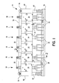
- Figure 1 is a front view of blow pin assemblies mounted at a blow station of a shuttle type blow molding machine;
- Figure 2 is a side view, partially broken away, taken
generally along
line 2--2 of Figure 1; and - Figures 3 and 4 are views like Figure 2 illustrating operation of the blow molding machine at the blow station.
-
- Shuttle
blow molding machine 10 includes twopart mold 12 defining a plurality ofcavities 14 for blow molding bottles when closed and a mold shift drive for shuttling the mold between a parison station where a parison is extruded down into the open mold for each mold cavity andblow station 16 where parisons captured in the mold cavities are blown to form aseptic bottles and are sealed closed to maintain sterility. The machine also includes a drive for opening and closing the molds. The mold shift drive and the opening and closing drive are conventional and are not illustrated. - Figure 1 illustrates a number of
blow pin assemblies 18 atblow station 16. Eachblow pin assembly 18 is located above amold cavity 14 and a captured parison in the cavity when the mold is at the blow station. - Each
assembly 18 includes anelongate blow pin 22 having an upper end mounted in ablock 24 and alower end 26 extending through the center of ablow pin housing 28. The blow pin is moveable axially relative to the housing from a retracted dwell position shown in Figure 2 wherepin end 26 is located in sterileannular chamber 30 and an extended blow position shown in Figure 4 where theend 26 of the pin projects below the housing. Theblow pin 22 includes an axialblow air tube 32 having a lower end forming adischarge mouth 34 at thelower end 26 of the blow pin.Tube 32 forms a blow air passage extending from a source of high-pressure, sterile blow air (not illustrated) through a control valve (not illustrated) and blowair inlet port 35 onblock 24 to the upper end oftube 32.Mouth 34 is recessed a short distance into the end of the blow pin to prevent contamination of the tube by contact with a non-sterile object. Contact could occur during setup, maintenance or modification of the blow molding machine. - An
annular discharge passage 36surrounds tube 32 in the blow pin and extends fromannular inlet 38, surroundingmouth 34 oftube 32 at the lower of the blow pin, along the length of the pin to block 24. The upper end ofpassage 36 is connected to a low-pressure vacuum port (not illustrated) which is connected to a low-pressure vacuum source (not illustrated) through a control valve (not illustrated) . -
Blow pin housing 28 includes lowercylindrical member 40 defining lower mouth 42, centralcylindrical member 44 and uppercylindrical member 46 defining anupper opening 47. The threemembers bolts 48engaging members Blow pin 22 includes acylindrical member 50 positioned adjacentcentral housing member 44 and moveable with the blow pin up and down relative tomember 44.Member 50 is held in place on the blow pin between cylindrical upper andlower clamps - Two impermeable
rolling diaphragms housing 28 and the blow pin to seal the upper end ofchamber 30 from atmospheric air outside the assembly and pin. As illustrated in Figure 2, the outer circumferential edge ofdiaphragm 56 is clamped betweenhousing members diaphragm 56 is clamped betweenmember 50 andlower clamp 54. The outer circumferential edge ofseal 58 is clamped betweenmembers seal 58 is clamped betweenmember 50 andupper clamp member 52. - Each
diaphragm member 44 and the outer surface ofmember 50 and rolls along the surfaces aspin 22 moves relative to thehousing 28. The 180 degree bends in the seals face each other and the portions of theseals engaging members - The two
diaphragm seals member 44 and the exterior surface ofmember 50 between the seals define a closedannular chamber 60 between the blow pin and housing. Sterileair inlet port 62 incentral member 44 communicateschamber 60 withvacuum source 64 throughvacuum line 66.Source 64 maintainschamber 60 below atmospheric pressure to assure that there is a pressure differential extending across each of the diaphragm seals. The differential pressure maintains flush engagement between the seals and the surfaces ofmembers member 50 are tapered slightly to facilitate flush engagement with the diaphragm seals.Seals - Other types of seals or even a single seal may be used, if desired.
- When
blow pin 22 is retracted as shown in Figure 2, the lower end of the pin is located inchamber 30.Opening 68 is formed inmember 40 and is connected to a source of low-pressuresterile air 70 throughline 72. Sterile air is continuously flowed throughpassage 68 tochamber 30. The sterile air surrounds the blow pin and flows axially along the blow pin in laminar flow and out the circular opening between the lower end of the blow pin and mouth 42. The sterile laminar flow adheres to the pin and, due to the Coanda effect, is drawn over the downwardly facing end of the blow pin to prevent atmospheric air from contaminating the pin. In this way, sterile air supplied throughpassage 68 protects the retracted blow pin from contamination by unsterile atmospheric air. Sterile air is flowed inchamber 30 when the pin is extended as shown in Figure 4. The diameter of the pin is slightly less than the diameter of mouth 42, permitting sterile air fromchamber 30 to flow down along the circumference of the extended pin and into the top ofmold cavity 14 as illustrated. This flow protects the extended blow pin from contamination. -
Block 24 in eachassembly 18 is mounted onhorizontal support block 76.Blow pin housings 28 are mounted onhorizontal plate 78, which is supported by two upwardly extendingguideposts 80 at the ends of the plate. Theposts 80 extend throughsleeve bearings 82 mounted onblock 76 to permit vertical movement ofplate 78 relative to block 76.Collars 79 onposts 80 prevent movement ofplate 78 below the position of Figure 1. Two fixed,vertical posts 84 supportadjustable stop members 86, shown in Figures 2-4. A pair ofstop fingers 88 onplate 78 engagestop members 86 to limit downward movement of the plate andblow pin housings 28 relative to block 76 and blocks 24. Gravity normally holdsplate 78 belowblock 76 withcollars 79 engaging bearings as shown in Figure 1. - A suitable blow pin drive (not illustrated) lowers and raises
block 76 to move theblow pin assemblies 18 down toward the two-part mold 12 and to withdraw blow pin assemblies up from the mold. During lowering,fingers 88 engage stops 86 with the blow pins withdrawn inchambers 30 and plate 78 a short distance above the mold. Continued lowering ofblock 76 and blocks 24 extends the blow pins into theneck portions 90 of the mold cavities to engage the parisons prior to blow molding, as shown in Figure 4. - During startup of
machine 10chambers 30, the surfaces of the blow pins located below rolling diaphragm seals 56, all blow air passages including theblow tubes 32,exhaust passages lines 72 are sterilized using high temperature steam. After initial sterilization, sterile air at a pressure less than 0.07 bar (one pound per square inch) is flowed fromsource 70 throughlines 72 intochambers 30. The low pressure sterile air completely fills the chambers belowseals 56 and establishes laminar axial flows of sterile air along the ends of the retracted blow pins and out through mouths 42. Low pressure air is required in order to achieve the desired laminar flow along the blow pin. Higher pressure air would create turbulent flow. Due to the Coanda effect, sterile air is drawn across the exposed ends of the pins overmouths 34 of theblow tubes 32 andmouths 38 ofexhaust passages 36. The continuous flow of sterile air intochambers 30 and around, along and over the ends of the retracted blow pins maintains the sterility of the blow pins by preventing atmospheric air, which may contain non-sterile contaminants, from contacting the retracted blow pin. Sterile air fillschambers 30 at a positive pressure. During the interval the blow pins are extended, sterile air flows out fromchambers 30 through 0.5 mm (0.02 inch) clearances between each side of the pin and mouth, as indicated byarrows 92 in Figure 4. This flow protects the extended pin from contamination. - A cycle of operation of
blow molding machine 10 will now be described. - The cycle starts with the
open mold 12 at the extrusion station and with parison extruders located above each open mold cavity extruding a parison down between the mold halves. The molds close over the parisons to capture each parison in a cavity. The captured parisons are severed from the remainders of the parisons and the closed mold is shifted to blowstation 16 with each closed cavity and parison located under ablow pin assembly 18.Assemblies 18 are in the elevated position as shown in Figure 2 withfingers 88 abovestop members 86. - Next, the blow pin drive lowers
block 76 to move the blow pins,plate 78 andpin housings 28 toward closedmold 12.Plate 78 andhousings 28 are lowered with the blow pins untilfingers 88 engage stops 86. This engagement stops lowering of plate 78 a short distance above the top of theclosed mold 12. - Further lowering of
support block 76 extends the blow pins outwardly fromchambers 30 and down into theneck portions 90 of the mold cavities. Figure 4 illustrates the position withplate 78 fully lowered,fingers 88 engagingstops 86 and the blow pins fully extended. Lower ends of the pins seal the parisons at the upper portions of the mold cavities. Blowtube mouths 34 andexhaust passage mouths 38 open into the captured parisons. - Blow air is then flowed through
blow tubes 32 and into the interior of the parisons to expand the molten parisons outwardly and form bottles having a shape defined by the shape of the mold cavities. The blow air, which may have a pressure of about 6 bar (88 pounds per square inch), holds the molten parisons against the walls of the cavities. The molds extract heat from the molten plastic so that the plastic quickly sets to form bottles. However, relatively large bodies of plastic at the bottom of the bottles remains molten after the remainder of the bottles are set. This plastic releases heat during cooling, prior to stabilization of the plastic. - After the bottle is blown and set, a valve between the source of blow air and blow
tubes 34 is closed and a valve in the line connecting ports 39 to a source of subatmospheric air, which may be at a pressure of about - 0.5 bar (- 7 PSI), is opened to extract blow air from the interior of the bottle. - The
exhaust passages 36 are connected to the source of low-pressure air for a period sufficient to reduce the pressure in the bottles to a desired pressure below atmospheric pressure. When this occurs, the mold opens and shuttles back to the extrusion station leaving the bottles suspended on the blow pins. Sealing tooling located in masking arms below the extended blow pins and above the necks of the bottles close to seal the interiors of the bottles as the arms grip the bottles. The plastic adjacent the sealing tooling is kept hot to facilitate sealing. The sealing tooling may be of the type shown in U.S. Patent No. 5,037,684. The negative pressure applied toexhaust passages 36 is deactivated after the bottles are sealed. - After the bottle is sealed closed at a subatmospheric pressure the masking arms hold the bottles and the blow pin drive lifts block 76 up to extract the blow pins from the tops of the bottles and return the blow pin assemblies to the start position shown in Figures 1-3. The arms transfer the bottle from the machine.
- During the time the blow pins are extended into the molds sterile air continues to be flowed into
chamber 30 and out of the chamber through the narrow gap between the blow pin and chamber mouth 42. This air floods the exposed blow pins to prevent atmospheric air from contaminating the blow pins. Additionally, the high temperature of the molten plastic in the parison, about 200 degrees Celsius (400 degrees F.), assists in maintaining sterility of the blow pin by heating the surface of the pin above a sterilizing temperature. - The set bottles withdrawn from the mold cavities contain bodies of molten or near molten plastic. These bodies gradually cool and release heat, which heats the subatmospheric air in the bottle and increases the pressure of the air in the bottle. When the latent heat is fully released from the plastic bodies the pressure in the bottle has been increased substantially to atmospheric pressure so that there is no significant pressure differential across the walls of the bottle and the bottle is in its desired molded shape when the plastic in the bottle stabilizes. Blowing of aseptic plastic bottles are sealed at subatmospheric pressure to avoid deformation of the bottle when fully stabilized is more fully explained in U.S. Patent No. 5,037,684.
- After the bottles are removed from the open mold, the mold is moved back to the parison station to complete the cycle of operation of molding
machine 10. -
Exhaust passage 36 is maintained at a negative pressure during evacuation of the bottle until the bottle is sealed closed at the desired negative pressure. The exhaust passage is separate from the blow passage so that exhaust air does not flow through the sterile blow passage. This is important in the case a ruptured parison or bottle is blow molded and permits contaminated air to flow into the bottle or parison through the rupture. This air may contain contaminants and is withdrawn throughexhaust passage 36. Contaminants in the exhaust air can render the exhaust passage nonsterile. Contaminates, however, cannot enterblow tube 32 because during exhaustion of blowgas exhaust passage 36 is maintained at a pressure lower than the pressure in the blow tube. This assures that a rupture bottle does not destroy the sterility of the blow pin. Contaminants in the blow passage could destroy sterility of the bottles. - During mold changeover, and modification or adjustment of the molding machine the sterility of retracted blow pins may be maintained by continuing to flow sterile air from
source 70 intochambers 30 and around the blow pins and out the chamber as previously described. Maintenance of the sterile flow of air around the blow pins permits startup of the machine after a mold change, adjustment or modification without the necessity to resterilize the pin assemblies. The lower ends of the blow tubes are located short distances above the bottom of the blow pins to further protect the sterility of the tubes. - Use of two rolling diaphragm seals 56 and 58 with a
vacuum chamber 60 between the seals provides redundant protection ofsterile chamber 30 from contamination by atmospheric air. A leak through the lowerblowing diaphragm seal 56 could result in sterile air fromchamber 30 flowing into the low-pressure chamber 60. This air would be drawn away from the machine tolow pressure source 64 without contamination. A leak through the upper rollingdiaphragm seal 58 would result in the flow of atmospheric air into the low-pressure chamber 60. Such flow, however, would likewise be drawn away to low-pressure source 64 without jeopardizing the sterility ofchamber 30. In the unlikely event of small leaks of bothseals pressure chamber 60 and safely away to low-pressure source 64 without contamination ofchamber 30. - The blow pins are maintained sterile by flowing sterile air into the blow pin housings, along the pins and around and ends of the pins. Obviously, the blow pins could be maintain sterile by flowing a sterile gas other than air into the housings and around the pins as described.
- While we have illustrated and described preferred embodiments of our invention, it is understood that this is capable of modification, and we therefore do not wish to be limited to the precise details set forth, but desire to avail ourselves of such changes and alterations as fall within the purview of the following claims.
Claims (17)
- A blow pin assembly (18) for use in blow molding aseptic plastic bottles, the assembly including:A) an elongate blow pin (22) having a blow end (26), the pin (22) including an internal blow air passage (32) extending along the pin (22) and having a blow mouth (34) at the blow end (26) of the pin (22);B) a blow pin housing (28) surrounding the blow pin (22), the housing (28) defining an upper opening (47) and a lower mouth (42), and a sterile gas inlet port opening (35) into a first circumferential chamber (30) between the housing (28) and the blow pin (22);C) a first circumferential seal (58) adjacent the upper opening (47), said first seal (58) extending between the housing (28) and the blow pin (22), said seal (58) closing the top of the chamber (30) and permitting axial movement of the blow pin (22) relative to the housing (28) between a retracted position where the blow end (26) of the pin (22) is adjacent the housing (28) and an extended position where the blow end (26) of the pin (22) is extended outwardly from the housing (28) in position to blow a parison held in a closed mold adjacent the housing (28), the surface of the pin (22) below the first seal (58) being sterile; andD) a drive for moving the blow pin (22) between the retracted and extended positions;E) wherein when the blow pin (22) is in the retracted position sterile gas flowed into the chamber (30) through the sterile gas inlet port (35) , flows along the blow pin (22) and across the blow end (26) of the pin (22) to shield the pin (22) from contamination by atmospheric air.
- The assembly as in claim 1 including a circumferential clearance between the blow pin (22) and the mouth of the housing (42) when the blow pin (22) is in the extended position wherein sterile gas from the chamber (30) flows through the clearance and around the extended blow pin (22) to shield the pin (22) from contamination by atmospheric air.
- The assembly as in claim 1 or claim 2 wherein the first circumferential seal (58) includes a first circumferential portion mounted on the blow pin (22), a second circumferential portion mounted on the housing (28) and a circumferential flexible portion extending between said first and second portions.
- The assembly as in claim 3 wherein said flexible portion comprises a diaphragm.
- The assembly as in claim 4 wherein the diaphragm includes a circumferential bend.
- The assembly as in claim 5 wherein said bend is located between two circumferential diaphragm portions, such portions extending away from said bend in the same direction.
- The assembly as in claim 6 wherein said diaphragm portions contact the blow pin (22) and housing (28), respectively.
- The assembly as in any preceding claim including a second seal (56) extending between the housing (28) and the blow pin (22), the second seal (56) comprising a flexible diaphragm spaced a distance along the pin (22) from the first seal (58); a circumferential chamber (60) located between said seals (56, 58), the blow pin (22) and the housing (28); and a vacuum port (62) opening into said annular chamber (60) wherein a source of vacuum (64) connected to the vacuum port (62) maintains the circumferential chamber (60) at subatmospheric pressure.
- The assembly as in any preceding claim wherein the blow pin (22) includes an exhaust passage (36) separate from the blow passage (32), the exhaust passage (36) extending along the pin (22) and having an exhaust mouth (38) at the blow end (26) of the pin (22) adjacent the blow mouth (34), wherein when the blow pin (22) is in the extended position sterile blow air is flowed into a parison through the sterile blow tube to blow the parison and, after blowing of the parison, blow air is exhausted from the bottle through the exhaust passage (36) only to prevent contamination of the sterile blow tube (32) by contaminated air flowing into the parison or bottle due to a rupture.
- The assembly as in any preceding claim wherein the blow tube mouth (34) is recessed in the end of the blow pin (22).
- The assembly as in any preceding claim including a source of sterile gas at a pressure of about 0.07 bar and a gas line connecting the source to the sterile gas to the inlet port (35) wherein sterile gas at said pressure is flowed through the port (35) into the chamber (30), around and along the blow pin (22).
- A blow molding machine comprising the blow pin assembly (18) as in anyone of claims 1 to 11.
- A method of blowing a sealed aseptic plastic bottle using a blow molding machine having a blow pin (22) with a blow end (26), a sterile internal blow passage (32) extending from a source of sterile blow gas through the blow pin (22) to the end (26) of the pin (22), a blow pin housing (28) surrounding the blow pin (22) and a blow pin drive to move the blow pin (22) between extended and retracted positions, including the steps of:A) moving the blow pin (22) to the retracted position to locate an end portion of the pin (22) in the housing (28), flowing sterile gas into a chamber (30) between the pin (22) and housing (28) so that the sterile gas surrounds the pin (22) and flows axially along the pin (22) over the end (26) of the pin (22) and the end (34) of the blow passage (32) to maintain sterility of the end of the pin (22) and the passage (32);B) locating a closed blow mold with a parison captured in a blow cavity (14) adjacent the blow pin (22);C) moving the blow pin (22) outwardly from the housing (28) to an extended position to locate the end (26) of the blow pin (22) in the mold in contact with the parison and with the end of (34) the blow passage (32) communicating with the interior of the parison while continuing to flow sterile air outwardly from the housing (28) and along the blow pin (22) to maintain sterility of the extended blow pin (22);D) blowing sterile gas through the sterile blow passage (32), out the end (34) of the passage (32) and into the parison to blow the parison and form a sterile bottle;E) removing blow gas from the interior of the blown bottle while maintaining the sterility of the blow passage to reduce the pressure within the bottle;F) sealing the bottle closed after blow gas has been removed from the bottle;G) separating the blow pin (22) from the bottle, moving the blow pin (22) back to the retracted position in the housing (28) and continuing to flow sterile gas along the pin (22) and around the end (26) of the pin (22) to maintain the sterility of the pin (22) ; andH) opening the mold and removing the blown bottle.
- The method of claim 13 including the step of:I) exhausting blow gas from the blown bottle through an exhaust passage (36) in the blow pin (22) separate from the blow air passage (32) without exhausting gas through the blow passage (32).
- The method of claim 13 or 14 including the step of :I) exhausting sufficient blow gas from the bottle to reduce the interior pressure of the bottle below atmospheric pressure and then sealing the bottle closed at subatmospheric pressure.
- The method of claims 13, 14 or 15 including the step of:I) flowing the sterile gas into the chamber (30) at a pressure of about 0.07 bar or less.
- The method of claims 13, 14, 15 or 16 including the steep of:I) flowing sterile gas along the pin (22) in laminar flow.
Applications Claiming Priority (2)
| Application Number | Priority Date | Filing Date | Title |
|---|---|---|---|
| US09/861,315 US6635216B2 (en) | 2001-05-18 | 2001-05-18 | Blow molding machine and method |
| US861315 | 2001-05-18 |
Publications (2)
| Publication Number | Publication Date |
|---|---|
| EP1258336A1 true EP1258336A1 (en) | 2002-11-20 |
| EP1258336B1 EP1258336B1 (en) | 2005-01-26 |
Family
ID=25335475
Family Applications (1)
| Application Number | Title | Priority Date | Filing Date |
|---|---|---|---|
| EP02010965A Expired - Lifetime EP1258336B1 (en) | 2001-05-18 | 2002-05-16 | Blow molding machine and method |
Country Status (6)
| Country | Link |
|---|---|
| US (1) | US6635216B2 (en) |
| EP (1) | EP1258336B1 (en) |
| JP (1) | JP2002361718A (en) |
| AT (1) | ATE287788T1 (en) |
| DE (1) | DE60202713T2 (en) |
| ES (1) | ES2232696T3 (en) |
Cited By (7)
| Publication number | Priority date | Publication date | Assignee | Title |
|---|---|---|---|---|
| CN102247610A (en) * | 2010-05-20 | 2011-11-23 | 克朗斯股份有限公司 | Blow mould capable of being sterilized |
| ITVI20120050A1 (en) * | 2012-03-01 | 2013-09-02 | Stk Stocchi Progetti S R L Uninomi Nale | APPARATUS AND FORMING PROCEDURE, PARTICULARLY FOR PLASTIC CONTAINERS. |
| EP2540473A3 (en) * | 2011-06-27 | 2014-10-08 | Krones AG | Device and method for deforming plastic preforms into plastic containers with moving stretching rod sealed by rolling membrane |
| WO2015024642A1 (en) * | 2013-08-19 | 2015-02-26 | Khs Corpoplast Gmbh | Method and device for blow-molding containers which are sterile at least in some areas |
| WO2015070991A1 (en) * | 2013-11-18 | 2015-05-21 | Khs Gmbh | Device and method for producing sterile containers |
| WO2019048563A1 (en) * | 2017-09-08 | 2019-03-14 | Khs Corpoplast Gmbh | Molding and filling station |
| CN111196005A (en) * | 2020-01-09 | 2020-05-26 | 杨保长 | Injection molding machine for plastic processing |
Families Citing this family (18)
| Publication number | Priority date | Publication date | Assignee | Title |
|---|---|---|---|---|
| US7669390B2 (en) * | 2004-03-08 | 2010-03-02 | Medical Instill Technologies, Inc. | Method for molding and assembling containers with stoppers and filling same |
| US7707807B2 (en) * | 2004-03-08 | 2010-05-04 | Medical Instill Technologies, Inc. | Apparatus for molding and assembling containers with stoppers and filling same |
| CN101001782A (en) | 2002-09-03 | 2007-07-18 | 因斯蒂尔医学技术有限公司 | Sealed containers and methods of making and filling same |
| DE10254762A1 (en) * | 2002-11-22 | 2004-06-09 | Transcoject Gesellschaft für medizinische Geräte mbH & Co. KG | Process for producing and / or handling a high-purity object |
| TW200533657A (en) * | 2004-02-17 | 2005-10-16 | Esteve Labor Dr | Substituted pyrazoline compounds, their preparation and use as medicaments |
| DE102004041973B3 (en) * | 2004-08-31 | 2006-01-19 | Krones Ag | Air recycling in the blow molding process |
| FR2889672B1 (en) * | 2005-08-12 | 2009-08-07 | Sidel Sas | FUNCTIONAL ASSEMBLY FOR INSTALLATION FOR BLOWING CONTAINERS AND INSTALLATION COMPRISING SUCH AN ASSEMBLY |
| DE102005042926B4 (en) * | 2005-09-08 | 2015-02-05 | Krones Aktiengesellschaft | Method and device for controlling and regulating a hollow body manufacturing unit |
| US8071009B2 (en) * | 2005-10-17 | 2011-12-06 | Medical Instill Technologies, Inc. | Sterile de-molding apparatus and method |
| US7905113B2 (en) * | 2006-12-15 | 2011-03-15 | Emhart Glass S.A. | Cooling tube mechanism for an I. S. Machine |
| US7856852B2 (en) * | 2006-12-15 | 2010-12-28 | Emhart Glass S.A. | Cooling tube mechanism for an I. S. Machine |
| EP2657185B1 (en) * | 2008-05-20 | 2015-09-02 | Dai Nippon Printing Co., Ltd. | Beverage filling apparatus |
| DE102011008132A1 (en) * | 2011-01-04 | 2012-07-05 | Khs Corpoplast Gmbh | Method and device for blow-molding sterile containers |
| DE102011013120A1 (en) | 2011-03-04 | 2012-09-06 | Krones Aktiengesellschaft | Blow molding machine with sterile room and sterile blast air supply |
| DE102011016448A1 (en) * | 2011-03-29 | 2012-10-04 | Khs Corpoplast Gmbh | Method for sterilizing and device for blow molding of containers |
| JP6439920B2 (en) * | 2013-11-14 | 2018-12-19 | 大日本印刷株式会社 | Bottle sterilization method and apparatus |
| DE102013114801B3 (en) | 2013-12-23 | 2015-03-05 | Krones Ag | Device for forming plastic preforms into plastic containers with bellows return function |
| AT521270B1 (en) * | 2018-06-05 | 2019-12-15 | Engel Austria Gmbh | sealing |
Citations (3)
| Publication number | Priority date | Publication date | Assignee | Title |
|---|---|---|---|---|
| FR2405809A1 (en) * | 1977-06-30 | 1979-05-11 | Air Liquide | Cooling system for blow-moulded containers - injects cryogenic fluid together with continuing flow of moulding air |
| JPS6049919A (en) * | 1983-08-30 | 1985-03-19 | Aida Eng Ltd | Sterilizer for blow and injection mandrel station of plastic container molding machine |
| US4946366A (en) * | 1989-06-22 | 1990-08-07 | Graham Engineering Corporation | Needle assembly for blow molding aseptic bottles |
Family Cites Families (31)
| Publication number | Priority date | Publication date | Assignee | Title |
|---|---|---|---|---|
| US3021559A (en) | 1958-07-31 | 1962-02-20 | Shipton & Company Ltd E | Method of and apparatus for the manufacture of hollow plastic articles |
| US3089185A (en) | 1961-03-27 | 1963-05-14 | Settembrini Antoine Di | Method and apparatus for manufacturing hollow plastic objects |
| US3492106A (en) | 1965-10-25 | 1970-01-27 | Phillips Petroleum Co | Two needle blow molding process and apparatus |
| FR2091884B1 (en) | 1970-03-27 | 1974-05-03 | Raffinage Cie Francaise | |
| GB1296612A (en) | 1970-05-12 | 1972-11-15 | ||
| US3694424A (en) | 1970-10-13 | 1972-09-26 | Hunkar Laboratories | Method of internally cooling a blow molded article |
| US3717429A (en) | 1971-01-04 | 1973-02-20 | Phillips Petroleum Co | Apparatus for cooling the blow pin and plastic molding material during blow molding operation |
| FR2125133B1 (en) | 1971-02-12 | 1977-04-15 | ||
| DE2134166A1 (en) | 1971-07-09 | 1973-01-18 | Pmd Entwicklungswerk | Hand over hand blow moulding sterile plastic containers - in which sleeve on extrusion nozzle isolates tube and moulding completely |
| US3819317A (en) | 1972-10-30 | 1974-06-25 | Haskon Inc | Apparatus for blow molding and injecting cooling gas |
| US4150689A (en) | 1973-01-26 | 1979-04-24 | Britten George C | Core rod construction for blow-molding apparatus |
| FR2264646B1 (en) | 1974-03-22 | 1978-06-16 | Remy & Cie E P | |
| US4208852A (en) * | 1974-11-08 | 1980-06-24 | Pont-A-Mousson S.A. | Process for the aseptic packing of products and machine employing said process |
| US4173447A (en) | 1978-09-05 | 1979-11-06 | Ethyl Development Corporation | Apparatus for contact cooling the neck moil of blown hollow containers |
| FR2502059A1 (en) | 1981-03-20 | 1982-09-24 | Mach Transformat Plastiques | DEVICE FOR BLOWING HOLLOW STERILE BODIES OF PLASTIC MATERIAL |
| US4699585A (en) | 1984-09-28 | 1987-10-13 | Kautex-Werke Reinold Hagen Ag | Blow molding apparatus |
| DE3435592A1 (en) | 1984-09-28 | 1986-04-03 | Kautex Werke Reinold Hagen AG, 5300 Bonn | METHOD FOR PRODUCING HOLLOW BODIES FROM THERMOPLASTIC PLASTIC |
| DE3614229A1 (en) | 1986-04-26 | 1987-11-05 | Battenfeld Fischer Blasform | Process and apparatus for blow-moulding hollow bodies from a tubular parison of plastic |
| US4880581A (en) * | 1986-12-24 | 1989-11-14 | Alcon Laboratories, Inc. | Means and method for aseptic particle-free production of articles |
| US4948356A (en) | 1989-07-19 | 1990-08-14 | Graham Engineering Corporation | Tooling for sealing blow molded bottle |
| US5022544A (en) | 1989-07-19 | 1991-06-11 | Graham Engineering Corporation | Sealed bottle |
| US5037684A (en) | 1989-07-19 | 1991-08-06 | Graham Engineering Corporation | Blow molded aseptic bottle and method |
| US4950153A (en) | 1989-07-19 | 1990-08-21 | Graham Engineering Corporation | Blow molding apparatus |
| US5068075A (en) | 1989-07-19 | 1991-11-26 | Graham Engineering Corporation | Method of blow molding aseptic bottles |
| US5182122A (en) | 1989-08-31 | 1993-01-26 | Nissei Asb Machine Co., Ltd. | Apparatus for stretch blow molding hollow heat-resistant container |
| JPH0647269B2 (en) | 1989-08-31 | 1994-06-22 | 日精エー・エス・ビー機械株式会社 | Method and apparatus for molding heat-resistant hollow container |
| US5474735A (en) | 1993-09-24 | 1995-12-12 | Continental Pet Technologies, Inc. | Pulse blow method for forming container with enhanced thermal stability |
| DE4405743C2 (en) | 1994-02-23 | 1998-01-29 | Bekum Maschf Gmbh | Process and device for the production of hollow bodies from thermoplastic materials in a blowing process |
| US6214282B1 (en) * | 1995-08-23 | 2001-04-10 | The Japan Steel Works, Ltd. | Simultaneous filling blow molding method and apparatus |
| US5759218A (en) * | 1996-10-24 | 1998-06-02 | Allergan | Point of fill air system |
| US5851479A (en) | 1996-12-24 | 1998-12-22 | Owens-Brockway Plastic Products Inc. | Method and apparatus for blow molding hollow articles |
-
2001
- 2001-05-18 US US09/861,315 patent/US6635216B2/en not_active Expired - Lifetime
-
2002
- 2002-05-16 DE DE60202713T patent/DE60202713T2/en not_active Expired - Lifetime
- 2002-05-16 ES ES02010965T patent/ES2232696T3/en not_active Expired - Lifetime
- 2002-05-16 EP EP02010965A patent/EP1258336B1/en not_active Expired - Lifetime
- 2002-05-16 AT AT02010965T patent/ATE287788T1/en not_active IP Right Cessation
- 2002-05-20 JP JP2002143935A patent/JP2002361718A/en active Pending
Patent Citations (3)
| Publication number | Priority date | Publication date | Assignee | Title |
|---|---|---|---|---|
| FR2405809A1 (en) * | 1977-06-30 | 1979-05-11 | Air Liquide | Cooling system for blow-moulded containers - injects cryogenic fluid together with continuing flow of moulding air |
| JPS6049919A (en) * | 1983-08-30 | 1985-03-19 | Aida Eng Ltd | Sterilizer for blow and injection mandrel station of plastic container molding machine |
| US4946366A (en) * | 1989-06-22 | 1990-08-07 | Graham Engineering Corporation | Needle assembly for blow molding aseptic bottles |
Non-Patent Citations (1)
| Title |
|---|
| PATENT ABSTRACTS OF JAPAN vol. 009, no. 183 (M - 400) 30 July 1985 (1985-07-30) * |
Cited By (12)
| Publication number | Priority date | Publication date | Assignee | Title |
|---|---|---|---|---|
| CN102247610A (en) * | 2010-05-20 | 2011-11-23 | 克朗斯股份有限公司 | Blow mould capable of being sterilized |
| CN102247610B (en) * | 2010-05-20 | 2013-12-25 | 克朗斯股份有限公司 | Method of treating devices of plant for production of plastics material containers and blow mould thereof |
| EP2388125A3 (en) * | 2010-05-20 | 2014-04-09 | Krones AG | Sterilisable blow mould |
| EP2540473A3 (en) * | 2011-06-27 | 2014-10-08 | Krones AG | Device and method for deforming plastic preforms into plastic containers with moving stretching rod sealed by rolling membrane |
| US9573315B2 (en) | 2011-06-27 | 2017-02-21 | Krones Ag | Apparatus and method of shaping plastics material pre-forms into plastics material containers with stretch bar movement sealed off by rolling diaphragm |
| ITVI20120050A1 (en) * | 2012-03-01 | 2013-09-02 | Stk Stocchi Progetti S R L Uninomi Nale | APPARATUS AND FORMING PROCEDURE, PARTICULARLY FOR PLASTIC CONTAINERS. |
| WO2015024642A1 (en) * | 2013-08-19 | 2015-02-26 | Khs Corpoplast Gmbh | Method and device for blow-molding containers which are sterile at least in some areas |
| US10882241B2 (en) | 2013-08-19 | 2021-01-05 | Khs Corpoplast Gmbh | Method and device for blow-molding containers which are sterile at least in some areas |
| WO2015070991A1 (en) * | 2013-11-18 | 2015-05-21 | Khs Gmbh | Device and method for producing sterile containers |
| US10286590B2 (en) | 2013-11-18 | 2019-05-14 | Khs Gmbh | Device and method for producing sterile containers |
| WO2019048563A1 (en) * | 2017-09-08 | 2019-03-14 | Khs Corpoplast Gmbh | Molding and filling station |
| CN111196005A (en) * | 2020-01-09 | 2020-05-26 | 杨保长 | Injection molding machine for plastic processing |
Also Published As
| Publication number | Publication date |
|---|---|
| ES2232696T3 (en) | 2005-06-01 |
| JP2002361718A (en) | 2002-12-18 |
| DE60202713T2 (en) | 2005-06-30 |
| ATE287788T1 (en) | 2005-02-15 |
| EP1258336B1 (en) | 2005-01-26 |
| DE60202713D1 (en) | 2005-03-03 |
| US20020171179A1 (en) | 2002-11-21 |
| US6635216B2 (en) | 2003-10-21 |
Similar Documents
| Publication | Publication Date | Title |
|---|---|---|
| US6635216B2 (en) | Blow molding machine and method | |
| BRPI0611260A2 (en) | Method and apparatus for blow molding aseptic containers | |
| US11345073B2 (en) | Method and device for producing and filling containers | |
| US7648662B2 (en) | Method and device for processing preforms | |
| US8309011B2 (en) | Auxiliary device and method for finishing preforms | |
| DK152837B (en) | PROCEDURE FOR THE MANUFACTURE OF HERMETIC CLOSED, STERILE CONTAINERS AND APPARATUS FOR EXERCISING THE PROCEDURE | |
| US4946366A (en) | Needle assembly for blow molding aseptic bottles | |
| TWI523751B (en) | Blown nozzles and blow molding machines | |
| JP6072431B2 (en) | Aseptic blow molding machine that removes air in a sterilized state | |
| JP4827732B2 (en) | Method and apparatus for producing vials in a sterile environment | |
| KR101454185B1 (en) | Device for minimizing oxygen content | |
| US20120326358A1 (en) | Apparatus and method for shaping plastics material preforms | |
| JPS61229530A (en) | Thermoplastic tube article and molding method and device thereof | |
| JP2013507264A (en) | Blow molding valve block for blow molding | |
| US10286590B2 (en) | Device and method for producing sterile containers | |
| KR100582337B1 (en) | Blow molding apparatus and method of making the same | |
| BR0213915B1 (en) | container blowing or stretching / blowing installation. | |
| KR20140106411A (en) | Blow molding process and apparatus | |
| EP3888884B1 (en) | Apparatus and process for aseptically forming containers starting from parisons made of a thermoplastic material | |
| JP6734480B2 (en) | Apparatus and method for aseptic molding of containers starting from a parison made of thermoplastic material | |
| EP3172028B1 (en) | Method for moulding and sterilizing a container made of plastic material, device for moulding and sterilizing a container made of plastic material and moulding and sterilizing machine | |
| JP2562807B2 (en) | Aseptic blow molding equipment | |
| CN113929041B (en) | Container filling mechanism suitable for blow filling and sealing all-in-one machine | |
| CN214395522U (en) | Mould heating structure and have its vulcanizer | |
| JP2013086169A (en) | Sealing structure, sealing method, casting system using the same, and casting method |
Legal Events
| Date | Code | Title | Description |
|---|---|---|---|
| PUAI | Public reference made under article 153(3) epc to a published international application that has entered the european phase |
Free format text: ORIGINAL CODE: 0009012 |
|
| AK | Designated contracting states |
Kind code of ref document: A1 Designated state(s): AT BE CH CY DE DK ES FI FR GB GR IE IT LI LU MC NL PT SE TR |
|
| AX | Request for extension of the european patent |
Free format text: AL;LT;LV;MK;RO;SI |
|
| 17P | Request for examination filed |
Effective date: 20021126 |
|
| 17Q | First examination report despatched |
Effective date: 20030429 |
|
| AKX | Designation fees paid |
Designated state(s): AT BE CH CY DE DK ES FI FR GB GR IE IT LI LU MC NL PT SE TR |
|
| GRAP | Despatch of communication of intention to grant a patent |
Free format text: ORIGINAL CODE: EPIDOSNIGR1 |
|
| GRAS | Grant fee paid |
Free format text: ORIGINAL CODE: EPIDOSNIGR3 |
|
| GRAA | (expected) grant |
Free format text: ORIGINAL CODE: 0009210 |
|
| AK | Designated contracting states |
Kind code of ref document: B1 Designated state(s): AT BE CH CY DE DK ES FI FR GB GR IE IT LI LU MC NL PT SE TR |
|
| PG25 | Lapsed in a contracting state [announced via postgrant information from national office to epo] |
Ref country code: NL Free format text: LAPSE BECAUSE OF FAILURE TO SUBMIT A TRANSLATION OF THE DESCRIPTION OR TO PAY THE FEE WITHIN THE PRESCRIBED TIME-LIMIT Effective date: 20050126 Ref country code: AT Free format text: LAPSE BECAUSE OF FAILURE TO SUBMIT A TRANSLATION OF THE DESCRIPTION OR TO PAY THE FEE WITHIN THE PRESCRIBED TIME-LIMIT Effective date: 20050126 Ref country code: CH Free format text: LAPSE BECAUSE OF FAILURE TO SUBMIT A TRANSLATION OF THE DESCRIPTION OR TO PAY THE FEE WITHIN THE PRESCRIBED TIME-LIMIT Effective date: 20050126 Ref country code: BE Free format text: LAPSE BECAUSE OF FAILURE TO SUBMIT A TRANSLATION OF THE DESCRIPTION OR TO PAY THE FEE WITHIN THE PRESCRIBED TIME-LIMIT Effective date: 20050126 Ref country code: LI Free format text: LAPSE BECAUSE OF FAILURE TO SUBMIT A TRANSLATION OF THE DESCRIPTION OR TO PAY THE FEE WITHIN THE PRESCRIBED TIME-LIMIT Effective date: 20050126 Ref country code: FI Free format text: LAPSE BECAUSE OF FAILURE TO SUBMIT A TRANSLATION OF THE DESCRIPTION OR TO PAY THE FEE WITHIN THE PRESCRIBED TIME-LIMIT Effective date: 20050126 Ref country code: TR Free format text: LAPSE BECAUSE OF FAILURE TO SUBMIT A TRANSLATION OF THE DESCRIPTION OR TO PAY THE FEE WITHIN THE PRESCRIBED TIME-LIMIT Effective date: 20050126 |
|
| REG | Reference to a national code |
Ref country code: GB Ref legal event code: FG4D |
|
| REG | Reference to a national code |
Ref country code: CH Ref legal event code: EP |
|
| REG | Reference to a national code |
Ref country code: IE Ref legal event code: FG4D |
|
| REF | Corresponds to: |
Ref document number: 60202713 Country of ref document: DE Date of ref document: 20050303 Kind code of ref document: P |
|
| PG25 | Lapsed in a contracting state [announced via postgrant information from national office to epo] |
Ref country code: DK Free format text: LAPSE BECAUSE OF FAILURE TO SUBMIT A TRANSLATION OF THE DESCRIPTION OR TO PAY THE FEE WITHIN THE PRESCRIBED TIME-LIMIT Effective date: 20050426 Ref country code: SE Free format text: LAPSE BECAUSE OF FAILURE TO SUBMIT A TRANSLATION OF THE DESCRIPTION OR TO PAY THE FEE WITHIN THE PRESCRIBED TIME-LIMIT Effective date: 20050426 Ref country code: GR Free format text: LAPSE BECAUSE OF FAILURE TO SUBMIT A TRANSLATION OF THE DESCRIPTION OR TO PAY THE FEE WITHIN THE PRESCRIBED TIME-LIMIT Effective date: 20050426 |
|
| PG25 | Lapsed in a contracting state [announced via postgrant information from national office to epo] |
Ref country code: LU Free format text: LAPSE BECAUSE OF NON-PAYMENT OF DUE FEES Effective date: 20050516 Ref country code: IE Free format text: LAPSE BECAUSE OF NON-PAYMENT OF DUE FEES Effective date: 20050516 Ref country code: CY Free format text: LAPSE BECAUSE OF FAILURE TO SUBMIT A TRANSLATION OF THE DESCRIPTION OR TO PAY THE FEE WITHIN THE PRESCRIBED TIME-LIMIT Effective date: 20050516 |
|
| PG25 | Lapsed in a contracting state [announced via postgrant information from national office to epo] |
Ref country code: MC Free format text: LAPSE BECAUSE OF NON-PAYMENT OF DUE FEES Effective date: 20050531 |
|
| REG | Reference to a national code |
Ref country code: ES Ref legal event code: FG2A Ref document number: 2232696 Country of ref document: ES Kind code of ref document: T3 |
|
| NLV1 | Nl: lapsed or annulled due to failure to fulfill the requirements of art. 29p and 29m of the patents act | ||
| REG | Reference to a national code |
Ref country code: CH Ref legal event code: PL |
|
| PLBE | No opposition filed within time limit |
Free format text: ORIGINAL CODE: 0009261 |
|
| STAA | Information on the status of an ep patent application or granted ep patent |
Free format text: STATUS: NO OPPOSITION FILED WITHIN TIME LIMIT |
|
| ET | Fr: translation filed | ||
| 26N | No opposition filed |
Effective date: 20051027 |
|
| REG | Reference to a national code |
Ref country code: IE Ref legal event code: MM4A |
|
| PG25 | Lapsed in a contracting state [announced via postgrant information from national office to epo] |
Ref country code: GB Free format text: LAPSE BECAUSE OF NON-PAYMENT OF DUE FEES Effective date: 20060516 |
|
| GBPC | Gb: european patent ceased through non-payment of renewal fee |
Effective date: 20060516 |
|
| PG25 | Lapsed in a contracting state [announced via postgrant information from national office to epo] |
Ref country code: PT Free format text: LAPSE BECAUSE OF NON-PAYMENT OF DUE FEES Effective date: 20050626 |
|
| PGFP | Annual fee paid to national office [announced via postgrant information from national office to epo] |
Ref country code: FR Payment date: 20110616 Year of fee payment: 10 Ref country code: ES Payment date: 20110524 Year of fee payment: 10 |
|
| PGFP | Annual fee paid to national office [announced via postgrant information from national office to epo] |
Ref country code: IT Payment date: 20110530 Year of fee payment: 10 |
|
| PGFP | Annual fee paid to national office [announced via postgrant information from national office to epo] |
Ref country code: DE Payment date: 20110801 Year of fee payment: 10 |
|
| PG25 | Lapsed in a contracting state [announced via postgrant information from national office to epo] |
Ref country code: IT Free format text: LAPSE BECAUSE OF NON-PAYMENT OF DUE FEES Effective date: 20120516 |
|
| REG | Reference to a national code |
Ref country code: FR Ref legal event code: ST Effective date: 20130131 |
|
| REG | Reference to a national code |
Ref country code: DE Ref legal event code: R119 Ref document number: 60202713 Country of ref document: DE Effective date: 20121201 |
|
| PG25 | Lapsed in a contracting state [announced via postgrant information from national office to epo] |
Ref country code: FR Free format text: LAPSE BECAUSE OF NON-PAYMENT OF DUE FEES Effective date: 20120531 |
|
| PG25 | Lapsed in a contracting state [announced via postgrant information from national office to epo] |
Ref country code: DE Free format text: LAPSE BECAUSE OF NON-PAYMENT OF DUE FEES Effective date: 20121201 |
|
| REG | Reference to a national code |
Ref country code: ES Ref legal event code: FD2A Effective date: 20130820 |
|
| PG25 | Lapsed in a contracting state [announced via postgrant information from national office to epo] |
Ref country code: ES Free format text: LAPSE BECAUSE OF NON-PAYMENT OF DUE FEES Effective date: 20120517 |