EP1257162A2 - Protection of electronic apparatus against static electricity and erroneous operations - Google Patents
Protection of electronic apparatus against static electricity and erroneous operations Download PDFInfo
- Publication number
- EP1257162A2 EP1257162A2 EP02252484A EP02252484A EP1257162A2 EP 1257162 A2 EP1257162 A2 EP 1257162A2 EP 02252484 A EP02252484 A EP 02252484A EP 02252484 A EP02252484 A EP 02252484A EP 1257162 A2 EP1257162 A2 EP 1257162A2
- Authority
- EP
- European Patent Office
- Prior art keywords
- hard disc
- recording medium
- unit
- electronic apparatus
- container
- Prior art date
- Legal status (The legal status is an assumption and is not a legal conclusion. Google has not performed a legal analysis and makes no representation as to the accuracy of the status listed.)
- Withdrawn
Links
- 230000005611 electricity Effects 0.000 title abstract description 27
- 230000003068 static effect Effects 0.000 title abstract description 27
- 238000003780 insertion Methods 0.000 claims description 51
- 230000037431 insertion Effects 0.000 claims description 51
- 238000000034 method Methods 0.000 claims description 6
- 239000004020 conductor Substances 0.000 claims description 2
- 239000000758 substrate Substances 0.000 description 8
- 238000012986 modification Methods 0.000 description 4
- 230000004048 modification Effects 0.000 description 4
- 238000005192 partition Methods 0.000 description 4
- 238000013461 design Methods 0.000 description 2
- 230000006870 function Effects 0.000 description 2
- 239000011347 resin Substances 0.000 description 2
- 229920005989 resin Polymers 0.000 description 2
- 230000004044 response Effects 0.000 description 2
- RYGMFSIKBFXOCR-UHFFFAOYSA-N Copper Chemical compound [Cu] RYGMFSIKBFXOCR-UHFFFAOYSA-N 0.000 description 1
- 229910045601 alloy Inorganic materials 0.000 description 1
- 239000000956 alloy Substances 0.000 description 1
- 238000005452 bending Methods 0.000 description 1
- 210000000078 claw Anatomy 0.000 description 1
- 229910052802 copper Inorganic materials 0.000 description 1
- 239000010949 copper Substances 0.000 description 1
- 238000001514 detection method Methods 0.000 description 1
- 238000010586 diagram Methods 0.000 description 1
- 238000004519 manufacturing process Methods 0.000 description 1
- 239000000463 material Substances 0.000 description 1
- 239000007769 metal material Substances 0.000 description 1
- 238000000926 separation method Methods 0.000 description 1
- 238000005476 soldering Methods 0.000 description 1
- 239000010935 stainless steel Substances 0.000 description 1
- 229910001220 stainless steel Inorganic materials 0.000 description 1
- 238000012546 transfer Methods 0.000 description 1
Images



Classifications
-
- G—PHYSICS
- G11—INFORMATION STORAGE
- G11B—INFORMATION STORAGE BASED ON RELATIVE MOVEMENT BETWEEN RECORD CARRIER AND TRANSDUCER
- G11B33/00—Constructional parts, details or accessories not provided for in the other groups of this subclass
- G11B33/12—Disposition of constructional parts in the apparatus, e.g. of power supply, of modules
- G11B33/121—Disposition of constructional parts in the apparatus, e.g. of power supply, of modules the apparatus comprising a single recording/reproducing device
- G11B33/122—Arrangements for providing electrical connections, e.g. connectors, cables, switches
-
- G—PHYSICS
- G11—INFORMATION STORAGE
- G11B—INFORMATION STORAGE BASED ON RELATIVE MOVEMENT BETWEEN RECORD CARRIER AND TRANSDUCER
- G11B33/00—Constructional parts, details or accessories not provided for in the other groups of this subclass
- G11B33/12—Disposition of constructional parts in the apparatus, e.g. of power supply, of modules
- G11B33/125—Disposition of constructional parts in the apparatus, e.g. of power supply, of modules the apparatus comprising a plurality of recording/reproducing devices, e.g. modular arrangements, arrays of disc drives
- G11B33/126—Arrangements for providing electrical connections, e.g. connectors, cables, switches
-
- G—PHYSICS
- G11—INFORMATION STORAGE
- G11B—INFORMATION STORAGE BASED ON RELATIVE MOVEMENT BETWEEN RECORD CARRIER AND TRANSDUCER
- G11B33/00—Constructional parts, details or accessories not provided for in the other groups of this subclass
- G11B33/14—Reducing influence of physical parameters, e.g. temperature change, moisture, dust
- G11B33/1493—Electro-Magnetic Interference [EMI] or Radio Frequency Interference [RFI] shielding; grounding of static charges
-
- H—ELECTRICITY
- H05—ELECTRIC TECHNIQUES NOT OTHERWISE PROVIDED FOR
- H05K—PRINTED CIRCUITS; CASINGS OR CONSTRUCTIONAL DETAILS OF ELECTRIC APPARATUS; MANUFACTURE OF ASSEMBLAGES OF ELECTRICAL COMPONENTS
- H05K9/00—Screening of apparatus or components against electric or magnetic fields
- H05K9/0067—Devices for protecting against damage from electrostatic discharge
Definitions
- the present invention relates to an electronic apparatus, and in particular, to an electronic apparatus equipped with a recording medium container into which a magnetic hard disc, which serves as a magnetic recording medium, is detachably contained.
- a navigation system which is an electronic apparatus that can be handled directly by crews, mounted on a car has become popular.
- a conventional navigation system uses an information recording medium to store map data, which is for instance a CD (Compact Disc)-ROM or a DVD (Digital Video Disc or Digital Versatile Disc)-ROM.
- CD-ROM or DVD-ROM Digital Video Disc or Digital Versatile Disc
- a recent trial is that an information recording medium, such a CD-ROM or DVD-ROM, is replaced by an inexpensive, higher-memory-capacity, and rewritable hard disc (i.e., hard disc unit) to store map data therein.
- the hard disc can be mounted, there are many advantages such that map data are easier to be updated because user's individual data as well as map data can be stored due to a large capacity of the memory.
- a problem concerning static electricity has been pointed out. To be specific, it is frequently required that users have to remove a hard disc (i.e., a hard disc unit; a casing in which a hard disc medium is incorporated) from a navigation system to rewrite its old map data into new ones. The hard disc unit of which map data have been updated is again loaded into the navigation system. During such unloading and loading operations, static electricity will be to some extent accumulated on the user's body surface. The static electricity is transferred and charged onto the outer surface of the hard disc unit, which may have undesired influence on data stored on the hard disc.
- the electric charge on the hard disc unit may create high voltage such hat it is applied to electronic parts mounted on a substrate of the hard disc unit. Due to the application of the high voltage, there is a possibility that the electronic parts are damaged.
- the conventional navigation system is provided with no means for preventing erroneous operations to its power supply.
- a user unloads a hard disc unit therefrom to rewrite new map data to its hard disc.
- the user then loads the hard disc unit into the navigation system, before attaching the dressed cover onto the disc insertion inlet.
- the foregoing unloading and loading operations may cause various problems.
- a practical problem may arise when the hard disc unit is loaded or unloaded to or from the navigation system with the navigation system powered. That is, such unloading or loading operations may happen to spoil data written on the hard disc. Moreover, it is pointed out that if the navigation system is powered with no hard disc unit loaded, the system may operate erroneously.
- the present invention has been made with due consideration to the foregoing drawbacks, and a first object of the present invention is to provide an electronic apparatus capable of avoiding a magnetic recording medium from being damaged due to static electricity when the medium is loaded into an objective system.
- a second object of the present invention is to provide an electronic apparatus that is able to protect data written on a magnetic recording medium as well as electronic parts from static electricity during unloading or loading the medium from or to an objective system.
- a third object of the present invention is to provide an electronic apparatus and a method for controlling power supply, which are able to protect data written on a magnetic recording medium from erroneous procedures in loading the medium into an objective system and to prevent the objective system from operating erroneously.
- the present invention provides an electronic apparatus comprising: a recording medium container into which a recording medium unit is detachably loaded and in which a guide passage for loading/unloading the recording medium unit is formed; and an earth-contacting member is disposed in the guide passage.
- the static electricity can securely be grounded via an earth-contacting member before the recording medium unit is connected to a connector attached in the recording medium container. That is, the static electricity passes directly to the earth, with data stored in a recording medium protected. Additionally, this grounding of the static electricity prevents other electronic parts incorporated in the electronic apparatus from being damaged.
- the recording medium container is a casing made of conductive material and the earth-contacting member is disposed at a predetermined position around the casing. It is also preferred that the earth-contacting member is a contacting piece formed on the casing, the contacting piece being made to come in contact with an outer surface of the recording medium unit to be loaded.
- the casing has an insertion inlet through which the recording medium unit is inserted and the contacting piece is formed in a vicinity of the insertion inlet.
- the recording medium unit is, for example, a hard disc unit including a hard disc on which information is magnetically recorded.
- the present invention provides an electronic apparatus comprising: a recording medium container into which a recording medium unit is detachably loaded and that has an insertion inlet through which the recording medium unit is loaded thereinto; a cover detachably attached to the insertion inlet of the recording medium container; a first detector configured to detect a first state in which the cover has removed from the insertion inlet; a second detector configured to detect a second state in which the recording medium unit has unloaded from the recording medium container; and stopping means configured to stop supplying power from a power supply to a load if at least one of the first and second detectors detect at least one of the first and second states.
- This configuration makes it possible that, when removal of the cover from the insertion inlet and/or unloading of the recording medium from the container are detected through the first and second detectors, the power from a power supply is forcibly stopped to be supplied.
- the recording medium unit is loaded or unloaded, data stored in its recording medium are protected from erroneous operations and the electronic apparatus is also avoided from being erroneously operated.
- the detectors are disposed in parallel at the insertion inlet. It is also preferred that the cover has a protrusion formed thereon and the first detector is configured to selectively detect either one of a contact to the protrusion and a non-contact from the protrusion. Still preferably, the recording medium has an overhanging member formed on a rear end of the recording medium and the second detector is configured to selectively detect either one of a contact to the overhanging member and a non-contact from the overhanging member.
- a method for controlling power supply in an electronic apparatus comprising a recording medium container into which a recording medium unit is detachably loaded and that has an insertion inlet through which the recording medium unit is loaded thereinto and a cover detachably attached to the insertion inlet of the recording medium container, the method comprising the steps of: first detecting a first state in which the cover has removed from the insertion inlet; second detecting a second state in which the recording medium unit has unloaded from the recording medium container; and stopping supplying power from a power supply to a load if at least one of the first and second states is detected.
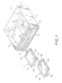
- Fig. 1 shows a navigation system to which one embodiment of an electronic apparatus according to the present invention is applied
- Fig. 2 is a front view of the navigation system.
- the navigation system shown by Figs. 1 and 2 has a not-shown front cover secured on a front panel thereof, but the navigation system is shown with the front cover removed, the front cover being able to be opened and closed freely.
- the navigation system includes a rectangular, box-like bottomed frame 1, which is for example incorporated within a recessed portion of the dashboard of a vehicle.
- a hard disc container serving as a recording medium container
- a PC card container 3 serving as a recording medium container
- a substrate/fan container 4 can be inserted into the PC card container 3.
- This PC card container 3 is positioned next to the hard disc container 2, while the substrate/fan container 4 is positioned at the side of the rears of both the hard disc container 2 and the PC card container 3.
- a ROM drive unit (not shown) to drive a CD-ROM or DVD-ROM is mounted above both of the hard disc container 2 and the PC card container 3.
- the PC card which serves as the foregoing card type of recording medium, can be used for storing information at both a home-use personal computer and the navigation system according to the present embodiment. Also, among a plurality of electronic apparatuses, the PC card can be used as a common recording medium to record pieces of information.
- a front panel 5 is secured as shown in Figs. 1 and 2.
- the front panel 5 can be seen after the front cover is removed.
- a dressed cover 6 is disposed.
- a hard disc insertion inlet 9 to load and unload two hard disc units 7 and 8 serving as magnetic recording medium units of the present invention can be seen.
- the hard disc units 7 and 8 include therein hard discs 7 h and 8h, respectively.
- the hard disc insertion inlet 9 is continuously coupled with the hard disc container 2.
- the navigation system is shown with the two hard disc units 7 and 8 unloaded.
- one hard disc unit 7 memorizes various types of data, such as map data and individual music data, while the remaining hard disc unit 8 memorizes data of, for example, music information recorded by a user for private use.
- the front panel 5 is formed to be almost perpendicular to the running direction of the vehicle.
- each of the hard disc units 7 and 8 On both the longitudinal sides of each of the hard disc units 7 and 8, as shown in Fig. 1, rod-like slide members 7a (8a) are secured along their sides. In addition, on the front side to be inserted ahead of each hard disc unit 7 (8), pluralities of pins 7b (8b) to be connected with a later-described connector are built. An overhanging piece 7c is fixedly arranged at one side end of the rear of the hard disc unit 7 to extend in its width direction thereof. On the rear of each of the hard disc units 7 and 8, an insulating and flexible handle 7d (8d) made of plastic material is mounted for holding in loading and unloading each hard disc unit 7 (8).
- a card insertion inlet 10 with a cover is formed, through which the not-shown PC card is loaded and unloaded.
- the cover can be opened when such loading and unloading is needed.
- the card insertion inlet 10 is continuously led to the PC card container 3.
- An ejection button 11 is arranged next to the card insertion inlet 10 to eject the PC card.
- a ROM insertion inlet 12 is opened at the frontal upper location of the front panel 5 so as to load and unload the CD-ROM or DVD-ROM.
- the ROM insertion inlet 12 is continuously led to the drive unit to drive the ROM.
- a further ejection button 13 is placed next to the ROM insertion inlet 12 so that the ROM can be ejected.
- the hard disc container 2 includes a casing 15, as shown in Figs. 3A and 3B, which serves as a conductive case.
- the casing 15 is formed by bending a plate-like member, made of a conductive metal material such as stainless steel, into a flat box shape, but no bottom. That is, the casing 15 is structured into one body including a ceiling portion 16 and wall portions 17 built at both ends of the ceiling portion 16.
- a rail member 18 is secured along the longitudinal direction thereof in such a manner that the rail members 18 on both the wall portions 17 are paired face to face.
- two upper and lower guide grooves 19 and 20 are formed along the longitudinal direction of each rail member.
- the foregoing slide members 7a (8a) on both the sides of each hard disc unit 7 (8) can be inserted into the guide grooves 19 (20), and slid therealong with its guide, so that each of the hard disc units 7 and 8 can be loaded and unloaded.
- a spacing surrounded by both the pair of rail members 18 and the ceiling portion 16 functions as a loading/unloading passage 21 for the hard disc unit 7.
- the upper partition constituting the upper guide groove 19 together with its lower partition shown in Fig. 3A is bent in the form of an arc (refer to Figs. 3A and 3B).
- the upper partition constituting the lower guide groove 20 together with its lower partition in Fig. 3A is formed to be an oblique shape. Both of the arc form and oblique shape make it easier to insert the slide members 7a and 8a of the hard disc units 7 and 8 into the individual guide grooves 19 and 20.
- a substrate 22 On the inner rear of the casing 15, a substrate 22 is mounted, and two connectors 23 are secured to lateral upper and lower locations on the substrate 22.
- Each connector 23 is equipped with a body 24 made of heat-resistance resin and fastened on the substrate 22 and a cover member 25 formed in an approximately M-shaped in section, made of heat-resistance resin, and attached to the body 24 so that the cover member 25 can be swung.
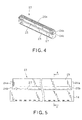
- each connector 23 With reference to Figs. 4 to 7, the structure of each connector 23 will be detailed.
- each connector 23 is formed into an approximately U-shape in section and standing-up walls 24a are integrally formed on both sides of the body 24 (refer to Figs. 4, 5 and 7). Through the root of each standing-up wall 24a, a slit 24 b is formed.
- the cover member 25 of each connector 23 is shaped into an approximately M-form in section, in which a plurality of through holes 25a into which a plurality of pins 7b or 8b are inserted are formed therethrough.
- protrusions 25b are formed to protrude in the longitudinal direction of the cover member 25.
- Each protrusion 25 is fitted with each slit 24b of the body 24.
- contact members 26 are placed through both the body 24 and the cover member 25.
- Each contact member 26 made of a gold-plated copper-based alloy is placed, one by one, toward each through hole 25a of the cover 25.
- One end of each contact member 26 extends up to almost each through hole 25a, while the other end thereof is taken out from the body 24 to be secured on the substrate by means of soldering.
- the pins 7b and 8b of the hard disc units 7 and 8 are inserted into the through holes 25a of the cover member 25, the pins 7b and 8b realize electrical contacts with the substrate 22 via the contact members 26.
- the cover member 25 is mounted to the body 24 with a slight spacing 27 left therebetween, wherein the protrusions 25a of each cover member 25 are fitted to the slits 24b of each body 24 and the plural contact members 26 are placed through both the body 24 and the cover member 25.
- the cover member 25 is coupled with the body 24 as a single structure, but can be swung in a direction shown by an arrow in Fig. 6.
- an approximate U-shaped notch 30 is formed at a certain location near to the hard disc insertion inlet 9 on the ceiling portion 16 of the casing 15.
- a contacting piece 31, which serves as a grounding contact member, is formed integrally with the notch 30 such that the contacting piece 31 slightly protrudes downward from the ceiling portion 16. Therefore, as illustrated in Fig. 8, when the hard disc unit 7 is inserted into the guide grooves 19, the contacting piece 31 will come into contact with the upper surface of the hard disc unit 7. This contact permits static electricity charged on the hard disc unit 7 to be grounded via the casing 15 to the frame 1, before the pins 7b of the hard disc unit 7 reach the through holes 25b of the cover member 25.
- switches 33a and 33b are arranged in line in the up-and-down direction.
- One switch 33a serves a first detector and the other switch 33b serves a second detector.
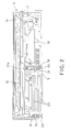
- These switches 33a and 33b have, as shown in Fig. 9, bodies 34a and 34b and operating pins 35a and 35b extendably protruding forward from the bodies 34a and 34b, respectively.
- design is made such that when the dressed cover 6 is mounted onto the hard disc insertion inlet 9, a protrusion 6a formed on the rear of the dressed cover 6 pushes the operating pins 35a to retract into its body 34a. Hence, the switch 33a (the first detector) is turned on. In contrast, when the dressed cover 6 is removed, the operating pin 35a becomes protruded from the body 34a, which makes the switch 33a turn off.
- the switch 33b (the second detector) is mounted such that, when the hard disc unit 7 is inserted along the guide grooves 19 and its pins 7b are inserted into the through holes 25a of the cover member 25 of the connector 23, the overhanging piece 7c mounted on the rear of the hard disc unit 7 pushes the operating pin 35b of the switch 33b. This makes the switch 33b turn on.
- the overhanging piece 7c separates from the switch 33b.
- the operating pin 35b restores to its protruded position, so that the switch 33b turns off.
- one switch 33a is in charge of detecting a contact or non-contact of the protrusion 6a mounted on the dressed cover 6 to the hard disc insertion inlet 9.
- the other switch 33b is in charge of detecting a contact or non-contact of the overhanging piece 7c mounted on the rear of the hard disc unit 7.
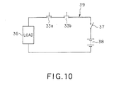
- Fig. 10 shows circuitry for protecting the power supply to which both the switches 33a and 33b are electrically connected.
- the switches 33a and 33b are connected in series to a load 36 consisting of one ore more drive units and connected to a backup power supply 38 via a main swatch 37, so that a serially connected loop 39 is formed among the switches 33a, 33b and 37, load 36, and backup power supply 38.
- This serially connected loop 39 functions as stopping means of the present invention.
- the turn-on of the main switch 37 will not allow the backup power supply 38 to supply power to the load 36.
- the load 36 will not be activated.
- the load 36 is not powered by the backup power supply 38 and is not driven, unless both of the switches 33a and 33b become turned on.
- map data stored in the navigation system be rewritten for update.
- a user is requested to remove the dressed cover 6, and holds the handle 7d of the hard disc unit 7 contained in the hard disc container 2 so that it is pulled out through the hard disc insertion inlet 9. Then the map data are rewritten for update.
- the operating pin 35a of the switch 33a extends outward, thus being turned off. Additionally, on drawing the hard disc unit 7 out from the hard disc insertion inlet 9, the overhanging piece 7c of the hard disc unit 7 separates from the switch 33b, so that its operating pin 35b extends outward to cause the switch 33b to turn off.
- the user who holds the handle 7d of the updated hard disc unit 7, then inserts it into the hard disc container 2 through the hard disc insertion inlet 9.
- the slide members 7a of the hard disc unit 7 are guided by the guide grooves 19 of the rail members 18 and slid therealong.
- the hard disc unit 7 slides with its upper surface in contact with the contacting piece 31.
- the charged static electricity on the hard disc unit 7 is obliged to flow to the frame 1 via the casing 15, before the pins of the hard disc unit 7 are inserted into the through holes 25a of the connector 23. That is, the charged static electricity is grounded directly to the dashboard of the vehicle through the frame 1.
- the dressed cover 6 is attached to the hard disc insertion inlet 9 as shown in Fig. 9, the protrusion 6a on the rear of the dressed cover 6 pushes the operating pin 35a of the switch 33a. This causes the switch 33a to turn on. Therefore, whenever the main switch is turned on after the turn-on of both the switches 33a and 33b, the backup power supply 38 is finally allowed to supply power to the load 36. This makes it possible to actuate the various drive units incorporated in the navigation system.
- the switches 33a and 33b are mutually connected in series, so that the backup power supply 38 is prohibited to supply power to the load 36 until the turn-on of both the switches is realized.
- the reason for the serial connection is as follows. For example, in cases where the switch 33a is disposed alone, only attaching the dressed cover 6 to the hard disc insertion inlet 9 allows the backup power supply 38 to operate to supply power to the load 36, even if the hard disc unit 7 has not been inserted in the hard disc container 2 yet. This gives rise to an inconvenience that the drive units operate without the hard disc unit 7.
- the arrangement of only the switch 33b will cause an undesirable situation under which the power supply from the backup power supply 38 to the loads 36 are still kept, even though the dressed cover 6 has already been removed.
- the foregoing inconveniences can be avoided by arranging the two switches mutually connected in series.
- the present invention is not restricted to the foregoing embodiment, but can be reduced into practice in other various modifications.
- the foregoing embodiment has adopted the contacting piece 31 (functioning as an earth-contacting member) arranged on the ceiling portion of the casing 15, but near to the hard disc insertion inlet 9.
- the contacting piece 31 is not limited to be arranged in such a position.
- the earth-contacting member is not always restricted to the shape of a claw, but may be formed as a linearly shaped piece.
- the earth-contacting member according to the present invention may be arranged for the hard disc unit 8, not limited to the configuration for the hard disc unit 7 described in the foregoing embodiment. Specifically, such earth-contacting member may be arranged in the loading/unloading passage 21 through which the hard disc unit 8 is inserted or ejected, so that, even when the hard disc unit 8 is loaded into the hard disc container 2 by an operator who is charged with static electricity, static electricity charged on the hard disc unit 8 is grounded through the earth-contacting member before the pins 8b of the hard disc unit 8 have inserted into the through holes 25a of the connector 23.
- switches 33a and 33b Another modification is concerned with the arrangement of the switches 33a and 33b.
- the forgoing embodiment has adopted the two switches 33a and 33b placed at the hard disc insertion inlet 9 in parallel in the up-and-down direction, they can be placed in the loading/unloading passage 21 that allows the hard disc unit 7 to be inserted or ejected. This mounting allows the switches 33a and 33b to turn on when the hard disc container 2 is loaded with the hard disc unit 7.
- the electronic apparatus described in the foregoing embodiment and its modifications is able to have various advantages.
- the contacting piece 31 serving as the earth-contacting member is disposed in the loading/unloading passage 21 for the hard disc unit 7.
- the static electricity charged on the hard disc unit 7 is securely grounded through the contacting piece 31 before the hard disc unit 7 is coupled with the connector 23.
- the data themselves stored in the hard disc unit 7 can be protected from the static electricity.
- other electronic parts can be avoided from receiving high voltage resulting from sparks caused by the static electricity.
- map data required for the navigation system is previously stored in the hard disc unit 7, the map data can be protected from being damaged by the static electricity. Additionally, when updating the map data of the hard disc unit 7, unloading and loading the hard disc unit 7 from and into the hard disc container 2 can be done with no electric influence on the main electric circuit of the system.
- the contacting piece 31 is designed to be disposed on the casing to contain the hard disc unit 7. It is therefore possible to make the disposal of the contacting piece 31 easier in its manufacture. Still, the contacting piece 31 formed on the casing 15 comes into contact with the outer surface of the hard disc unit 7 inserted into the container 2. This also makes it possible that the static electricity charged on the hard disc unit 7 via the contacting piece 31 is grounded in an easier and securer manner prior to the connection of the hard disc unit 7 to the connector 23.
- the contacting piece 31 is disposed nearer to the hard disc insertion inlet 9 on the casing 15. This makes it longer a distance (i.e., time) to allow the contacting piece 31 to contact the hard disc unit 7 during the insertion of the hard disc unit 7. Grounding the hard disc unit 7 can therefore be steadier.
- the insulating-material-made handles 7d and 8d that a user is able to grasp for insertion and ejection of the hard disc units 7 and 8 are attached to the hard disc units 7 and 8, respectively.
- the handles 7d and 8d are reluctant to an easier transfer of the static electricity from the user to the hard disc units 7 and 8.
- Each of the connectors 23 is made into one unit by fitting the cover 25 to the body 24 with the slight spacing 27 left therebetween and with the contact member 26 made to intervene therebetween, so that the cover 25 can be swung against the body 24. Therefore, if the pins 7b (8b) of the hard disc unit 7 (8) are positionally deviated to some extent from the through holes 25a of the connector 23 when the hard disc unit 7 (8) is inserted, the deviation can be absorbed by swings of the cover. Thus the hard disc unit 7 (8) can be inserted into the connector 23 with ease, facilitating user's operations necessary for such insertion.
- removing the dressed cover 6 from the hard disc insertion inlet 9 is detected by one switch 33a and unloading the hard disc unit 7 from the hard disc container 2 is detected by the other switch 33b.
- the backup power supply 38 is forcibly stopped to supply the power. Accordingly, if the hard disc unit 7 is inserted in a mistaken operation order, the electronic influence on the main circuit of the system can be avoided by the above automatic stop of the power supply. It is therefore possible to protect data stored in the hard disc unit 7 during the insertion and ejection thereof and erroneous operations toward the navigation system can be prevented steadily.
- switches 33a and 33b are disposed in parallel at the hard disc insertion inlet 9, so that they can be attached in an easier manner when being manufactured.
- one is disposed to detect contacts to the protrusion 6a formed on the dressed cover 6 and the other is disposed to detect contacts to the overhanging piece 7c at the rear of the hard disc unit 7. This disposal makes it possible to raise accuracy of the detection of the switches 33a and 33b.
Landscapes
- Engineering & Computer Science (AREA)
- Microelectronics & Electronic Packaging (AREA)
- Elimination Of Static Electricity (AREA)
- Fittings On The Vehicle Exterior For Carrying Loads, And Devices For Holding Or Mounting Articles (AREA)
- Details Of Connecting Devices For Male And Female Coupling (AREA)
- Navigation (AREA)
Abstract
Description
Claims (10)
- An electronic apparatus comprising a recording medium container (2) into which a recording medium unit (7) is detachably loaded and in which a guide passage (21) for loading/unloading the recording medium unit is formed, characterizing by comprising
an earth-contacting member (31) disposed in the guide passage. - The electronic apparatus of claim 1, wherein the recording medium container has a casing (15) made of conductive material and the earth-contacting member is disposed at a predetermined position around the casing.
- The electronic apparatus of either claim 1 or 2, wherein the earth-contacting member is a contacting piece (31) formed on the casing, the contacting piece being made to come in contact with an outer surface of the recording medium unit to be loaded.
- The electronic apparatus of claim 3, wherein the casing has an insertion inlet (9) through which the recording medium unit is inserted and the contacting piece is formed in a vicinity of the insertion inlet.
- The electronic apparatus of any of claims 1 to 4, wherein the recording medium unit is a hard disc unit (7) including a hard disc on which information is magnetically recorded.
- An electronic apparatus comprising a recording medium container (2) into which a recording medium unit (7) is detachably loaded and that has an insertion inlet (9) through which the recording medium unit is loaded thereinto, characterized by comprisinga cover (6) detachably attached to the insertion inlet of the recording medium container;a first detector (33a) configured to detect a first state in which the cover has removed from the insertion inlet;a second detector (33b) configured to detect a second state in which the recording medium unit has unloaded from the recording medium container; andstopping means (39) configured to stop supplying power from a power supply (38) to a load (36) if at least one of the first and second detectors detect at least one of the first and second states.
- The electronic apparatus of claim 6, wherein both of the detectors are disposed in parallel at the insertion inlet.
- The electronic apparatus of any claim 6 or 7, wherein the cover has a protrusion (6a) formed thereon and the first detector is configured to selectively detect either one of a contact to the protrusion and a non-contact from the protrusion.
- The electronic apparatus of any of claims 6 to 8, wherein the recording medium has an overhanging member (7c) formed on the recording medium and the second detector is configured to selectively detect either one of a contact to the overhanging member and a non-contact from the overhanging member.
- A method for controlling power supply in an electronic apparatus comprising a recording medium container (2) into which a recording medium unit (7) is detachably loaded and that has an insertion inlet (9) through which the recording medium unit is loaded thereinto and a cover (6) detachably attached to the insertion inlet of the recording medium container, the method comprising the steps of:first detecting a first state in which the cover has removed from the insertion inlet;second detecting a second state in which the recording medium unit has unloaded from the recording medium container; andstopping supplying power from a power supply (38) to a load (36) if at least one of the first and second states is detected.
Applications Claiming Priority (4)
| Application Number | Priority Date | Filing Date | Title |
|---|---|---|---|
| JP2001136413 | 2001-05-07 | ||
| JP2001136412A JP2002334570A (en) | 2001-05-07 | 2001-05-07 | Electronic equipment |
| JP2001136412 | 2001-05-07 | ||
| JP2001136413A JP4323729B2 (en) | 2001-05-07 | 2001-05-07 | Electronics |
Publications (2)
| Publication Number | Publication Date |
|---|---|
| EP1257162A2 true EP1257162A2 (en) | 2002-11-13 |
| EP1257162A3 EP1257162A3 (en) | 2003-08-13 |
Family
ID=26614707
Family Applications (1)
| Application Number | Title | Priority Date | Filing Date |
|---|---|---|---|
| EP02252484A Withdrawn EP1257162A3 (en) | 2001-05-07 | 2002-04-05 | Protection of electronic apparatus against static electricity and erroneous operations |
Country Status (2)
| Country | Link |
|---|---|
| US (2) | US6977795B2 (en) |
| EP (1) | EP1257162A3 (en) |
Cited By (3)
| Publication number | Priority date | Publication date | Assignee | Title |
|---|---|---|---|---|
| WO2005107352A1 (en) * | 2004-04-15 | 2005-11-10 | Thomson Licensing | Electromagnetic interference shield and heat sink apparatus |
| EP1619684A1 (en) * | 2004-07-21 | 2006-01-25 | Samsung Electronics Co., Ltd. | Data recording/reproducing apparatus |
| EP2598969A1 (en) * | 2010-07-30 | 2013-06-05 | Sagemcom Broadband SAS | Electronic apparatus comprising a recess for receiving an external module |
Families Citing this family (7)
| Publication number | Priority date | Publication date | Assignee | Title |
|---|---|---|---|---|
| AU2002351383A1 (en) * | 2002-12-16 | 2004-07-22 | Columbia Data Products, Inc. | Initiation sequences for performing protected computer operations |
| KR100640711B1 (en) * | 2004-02-19 | 2006-10-31 | 알프스 덴키 가부시키가이샤 | An apparatus for mounting a record medium |
| TWM283386U (en) * | 2005-05-27 | 2005-12-11 | Hon Hai Prec Ind Co Ltd | Electrical card connector |
| JP4921006B2 (en) * | 2006-03-20 | 2012-04-18 | 富士通株式会社 | Electronic equipment and unit products |
| TWM297564U (en) * | 2006-03-24 | 2006-09-11 | Advanced Connectek Inc | Connector of memory-card card |
| US20070263068A1 (en) * | 2006-04-07 | 2007-11-15 | Nesa International Incorporated | Mobile audio-video receiver with external memory receptacle |
| FR2939232B1 (en) * | 2008-11-28 | 2015-09-18 | Sagem Comm | DEVICE FOR HOSTING A HARD DISK AND ELECTRONIC EQUIPMENT PROVIDED WITH SUCH A DEVICE |
Family Cites Families (10)
| Publication number | Priority date | Publication date | Assignee | Title |
|---|---|---|---|---|
| US5122914A (en) * | 1984-01-17 | 1992-06-16 | Norand Corporation | Disk drive system with transportable carrier and mounting assembly |
| US4833554A (en) * | 1987-02-25 | 1989-05-23 | Tandon Corporation | Hard disk drive module and receptacle therefor |
| US5590047A (en) * | 1993-08-05 | 1996-12-31 | Clarion Co., Ltd. | Information processing apparatus |
| EP0717472A3 (en) * | 1994-12-13 | 1999-03-31 | Molex Incorporated | Grounding clip for IC-cards |
| US5643001A (en) * | 1996-07-26 | 1997-07-01 | The Whitaker Corporation | Memory card connector |
| DE69612747T2 (en) * | 1996-10-03 | 2001-08-23 | Hewlett-Packard Co. (N.D.Ges.D.Staates Delaware), Palo Alto | Mounting arrangement for fastening a system unit |
| US6088222A (en) * | 1996-11-14 | 2000-07-11 | Dell Usa, L.P. | Computer peripheral chassis frame structure having a split lance for location, electrical grounding, and load bearing of chassis carriers |
| US6262961B1 (en) * | 1997-11-18 | 2001-07-17 | Matsushita Electric Industrial Co., Ltd. | Disk loading device and disk cartridge |
| US6215666B1 (en) * | 1998-10-08 | 2001-04-10 | Sun Microsystems, Inc. | Giga-bit interface convertor bracket with enhanced grounding |
| US6557751B2 (en) * | 2001-06-12 | 2003-05-06 | Russell Anthony Puerini | Recyclable beverage container handle |
-
2002
- 2002-04-05 EP EP02252484A patent/EP1257162A3/en not_active Withdrawn
- 2002-04-10 US US10/119,117 patent/US6977795B2/en not_active Expired - Fee Related
-
2004
- 2004-06-09 US US10/863,236 patent/US6987641B2/en not_active Expired - Fee Related
Cited By (6)
| Publication number | Priority date | Publication date | Assignee | Title |
|---|---|---|---|---|
| WO2005107352A1 (en) * | 2004-04-15 | 2005-11-10 | Thomson Licensing | Electromagnetic interference shield and heat sink apparatus |
| US7529092B2 (en) | 2004-04-15 | 2009-05-05 | Thomson Licensing | Electromagnetic interference shield and heat sink apparatus |
| EP1619684A1 (en) * | 2004-07-21 | 2006-01-25 | Samsung Electronics Co., Ltd. | Data recording/reproducing apparatus |
| US7430751B2 (en) | 2004-07-21 | 2008-09-30 | Samsung Electronics Co., Ltd. | Data recording/reproducing apparatus with an improved structure for securely supporting a front panel |
| CN100426414C (en) * | 2004-07-21 | 2008-10-15 | 三星电子株式会社 | Data recording/reproducing apparatus |
| EP2598969A1 (en) * | 2010-07-30 | 2013-06-05 | Sagemcom Broadband SAS | Electronic apparatus comprising a recess for receiving an external module |
Also Published As
| Publication number | Publication date |
|---|---|
| US6977795B2 (en) | 2005-12-20 |
| US6987641B2 (en) | 2006-01-17 |
| EP1257162A3 (en) | 2003-08-13 |
| US20040223421A1 (en) | 2004-11-11 |
| US20020163757A1 (en) | 2002-11-07 |
Similar Documents
| Publication | Publication Date | Title |
|---|---|---|
| US6977795B2 (en) | Protection of electronic apparatus against static electricity by grounding | |
| US6594154B1 (en) | Key chain holders for small electronic circuit cards | |
| CN100492716C (en) | Battery device and electronic apparatus | |
| US7233489B2 (en) | Memory card drive and portable memory card drive | |
| US5768098A (en) | Portable electronic apparatus having receptacle for detachably storing card-type electronic component | |
| US7118421B2 (en) | Adapter device for electronic equipment | |
| US20060240713A1 (en) | Card connector | |
| EP0774727B1 (en) | IC Card reading/writing device | |
| JP5207196B2 (en) | Card connector with removal function | |
| CN1650319B (en) | Memory card connector with card misinsertion protection | |
| EP0106474B1 (en) | Magnetic bubble cassette | |
| JP4323729B2 (en) | Electronics | |
| CA1290023C (en) | Housing structure for paging receiver | |
| JP2002334570A (en) | Electronic equipment | |
| KR200440659Y1 (en) | USB memory device with sliding cover | |
| CN100356394C (en) | Loading device for storage medium having connection terminal | |
| JP2000174466A (en) | External device storage bay | |
| JP2003123028A (en) | Memory card loading device | |
| JPS6375888A (en) | Memory card insertion/extraction intention confirming device for information terminal equipment | |
| JP2544757B2 (en) | Information recording / playback device | |
| JPH0714294A (en) | Disk drive device | |
| JPH03102591A (en) | Reader writer for ic card | |
| HK1117988B (en) | Battery device and electronic apparatus | |
| JPH09179956A (en) | Ic card and ic card device using the same | |
| HK1120930B (en) | Battery device and electronic apparatus |
Legal Events
| Date | Code | Title | Description |
|---|---|---|---|
| PUAI | Public reference made under article 153(3) epc to a published international application that has entered the european phase |
Free format text: ORIGINAL CODE: 0009012 |
|
| AK | Designated contracting states |
Kind code of ref document: A2 Designated state(s): AT BE CH CY DE DK ES FI FR GB GR IE IT LI LU MC NL PT SE TR |
|
| AX | Request for extension of the european patent |
Free format text: AL;LT;LV;MK;RO;SI |
|
| PUAL | Search report despatched |
Free format text: ORIGINAL CODE: 0009013 |
|
| AK | Designated contracting states |
Designated state(s): AT BE CH CY DE DK ES FI FR GB GR IE IT LI LU MC NL PT SE TR |
|
| AX | Request for extension of the european patent |
Extension state: AL LT LV MK RO SI |
|
| RIC1 | Information provided on ipc code assigned before grant |
Ipc: 7G 11B 33/14 B Ipc: 7H 05K 9/00 A |
|
| 17P | Request for examination filed |
Effective date: 20030807 |
|
| AKX | Designation fees paid |
Designated state(s): DE FR GB |
|
| 17Q | First examination report despatched |
Effective date: 20090824 |
|
| STAA | Information on the status of an ep patent application or granted ep patent |
Free format text: STATUS: THE APPLICATION IS DEEMED TO BE WITHDRAWN |
|
| 18D | Application deemed to be withdrawn |
Effective date: 20091103 |