EP1257117A2 - Visual sensor - Google Patents
Visual sensor Download PDFInfo
- Publication number
- EP1257117A2 EP1257117A2 EP02253239A EP02253239A EP1257117A2 EP 1257117 A2 EP1257117 A2 EP 1257117A2 EP 02253239 A EP02253239 A EP 02253239A EP 02253239 A EP02253239 A EP 02253239A EP 1257117 A2 EP1257117 A2 EP 1257117A2
- Authority
- EP
- European Patent Office
- Prior art keywords
- image
- visual sensor
- reference light
- sensor according
- density
- Prior art date
- Legal status (The legal status is an assumption and is not a legal conclusion. Google has not performed a legal analysis and makes no representation as to the accuracy of the status listed.)
- Granted
Links
- 230000000007 visual effect Effects 0.000 title claims abstract description 59
- 239000002131 composite material Substances 0.000 claims description 39
- 239000006185 dispersion Substances 0.000 claims description 12
- 239000004065 semiconductor Substances 0.000 claims description 6
- 238000001514 detection method Methods 0.000 abstract description 4
- 230000009466 transformation Effects 0.000 description 23
- 238000000034 method Methods 0.000 description 9
- 230000015654 memory Effects 0.000 description 7
- 239000000203 mixture Substances 0.000 description 6
- 230000003321 amplification Effects 0.000 description 5
- 238000003199 nucleic acid amplification method Methods 0.000 description 5
- 101100328887 Caenorhabditis elegans col-34 gene Proteins 0.000 description 3
- RRLHMJHRFMHVNM-BQVXCWBNSA-N [(2s,3r,6r)-6-[5-[5-hydroxy-3-(4-hydroxyphenyl)-4-oxochromen-7-yl]oxypentoxy]-2-methyl-3,6-dihydro-2h-pyran-3-yl] acetate Chemical compound C1=C[C@@H](OC(C)=O)[C@H](C)O[C@H]1OCCCCCOC1=CC(O)=C2C(=O)C(C=3C=CC(O)=CC=3)=COC2=C1 RRLHMJHRFMHVNM-BQVXCWBNSA-N 0.000 description 3
- 230000005284 excitation Effects 0.000 description 3
- 230000006870 function Effects 0.000 description 2
- 229920006395 saturated elastomer Polymers 0.000 description 2
- 238000006243 chemical reaction Methods 0.000 description 1
- 230000003247 decreasing effect Effects 0.000 description 1
- 238000010586 diagram Methods 0.000 description 1
- 230000000694 effects Effects 0.000 description 1
- 239000004973 liquid crystal related substance Substances 0.000 description 1
- 238000006467 substitution reaction Methods 0.000 description 1
- 230000001360 synchronised effect Effects 0.000 description 1
Images


Classifications
-
- H—ELECTRICITY
- H04—ELECTRIC COMMUNICATION TECHNIQUE
- H04N—PICTORIAL COMMUNICATION, e.g. TELEVISION
- H04N23/00—Cameras or camera modules comprising electronic image sensors; Control thereof
- H04N23/70—Circuitry for compensating brightness variation in the scene
-
- H—ELECTRICITY
- H04—ELECTRIC COMMUNICATION TECHNIQUE
- H04N—PICTORIAL COMMUNICATION, e.g. TELEVISION
- H04N23/00—Cameras or camera modules comprising electronic image sensors; Control thereof
- H04N23/70—Circuitry for compensating brightness variation in the scene
- H04N23/74—Circuitry for compensating brightness variation in the scene by influencing the scene brightness using illuminating means
Definitions
- the present invention relates to a visual sensor using light receiving elements and a reference light beam such as laser beam in combination.
- the method disclosed in these Publications requires the density transformation of each pixel for adjusting densities of all pixels in a plurality of images, and comparison and substitution processing of the densities for obtaining a composite image.
- processing of multiplication and division based on a density ratio between the corresponding pixels in the plurality of images is required to burden a heavy load of arithmetic processing to a processor.
- Another method is known in which brightness of an incident light on each pixel is subjected to a logarithm transformation to determine density of each pixel in a view of processing for obtaining an edge image by differences between densities of adjacent pixels.
- a dynamic range of brightness of the incident light is compressed in this transformation.
- this method solves a problem of dependency of the definition of an edge image upon an intensity of lighting and a reflectance of an object, i.e., the definition of an edge image in a dark area in the captured image is low and the definition of an edge image in a bright area in the captured image is high to cause imbalance of image.
- Japanese Patent Publication No. 5-314253 describes the logarithm transformation of brightness in which a linear proportional transformation is applied in an area having a low brightness instead of the logarithm transformation in order to improve efficiency of usage of an image memory in the logarithm transformation of brightness.
- processing for the logarithm transformation of brightness is necessary for each pixel, to produce a considerable amount of arithmetic operation load to a processor.
- Japanese Patent Publication No. 9-311927 discloses a technique of reducing halation by extending a low brightness range (increasing density) and compressing a high brightness range (decreasing density) for respective pixels using a brightness transformation table.
- This method has an advantage in reducing arithmetic operation load but it is necessary to prepare brightness transformation tables for various applications and thus is not advantageous in general purpose. Further, it is difficult to find out theory in preparing the transformation table and thus is prepared based solely on experience.
- an intensity of light incident on the visual sensor varies in dependence upon a brightness of an object which changes in accordance with ambient such as intensity of lighting or sunshine and a deviation of placement of an object (relative position/posture between the object and the visual sensor). Therefore, there is a case of causing halation in an area necessary for detection or including useful information can not be obtained because of darkness of the image. It has been desired to expand a dynamic range of the visual sensor with respect to brightness of the object.
- An object of the present invention is to realize the logarithm transformation of brightness capable of expanding a dynamic range of a visual sensor by expanding a low brightness region and compressing a high brightness region with a little load of processing for arithmetic operations on a processor.
- Another object of the present invention is to perform a stable detection by the logarithm transformation of brightness in accordance with ON/OFF state of projection of a reference light beam such as laser beam in capturing images of an object using the reference light.
- the visual sensor comprises: image capturing means for capturing two-dimensional images of an object with controllable exposure periods; reference light projecting means for projecting reference light; storing means for storing parameters for altering the exposure period for capturing two-dimensional images by the image capturing means; image processing means for processing images captured by the image capturing means; reference light control means for controlling ON/OFF of the light projection by the reference light projecting means; and exposure period control means for controlling the exposure period so that the image capturing means captures images with different exposure periods in accordance with ON/OFF state of the light projection using the parameters stored in the storing means.
- the visual sensor comprises: the image capturing means; the reference light projecting means; the storing means; the image processing means; and the reference light control means; and exposure period control means for controlling the exposure period in capturing two-dimensional images by the image capturing means in accordance with a density of a part of the two-dimensional image corresponding a lightened part of the object when the light projection is ON, and controlling the exposure period in capturing two-dimensional images by the image capturing means in accordance with a density of a part or a whole area of the two-dimensional image when the light projection is OFF using the parameters stored in the storing means.
- the image processing means may include image composing means for producing a composite image based on densities of each pixel in a plurality of two-dimensional images captured with different exposure periods by the image capturing means.
- the visual sensor comprises: image capturing means for capturing a two-dimensional image of an object with a controllable gain of brightness; the reference light projecting means; storing means for storing parameters for altering the gain of brightness in capturing two-dimensional images by the image capturing means; the image processing means; the reference light control means; and gain control means for controlling the gain of brightness so that the image capturing means captures images with different gains of brightness in accordance with ON/OFF state of the light projection using the parameters stored in the storing means.
- the visual sensor comprises: the image capturing means for capturing a two-dimensional image of an object with a controllable gain of brightness; the reference light projecting means; the storing means for storing parameters for altering the gain of brightness in capturing two-dimensional images by said image capturing means; the image processing means; the reference light control means; and gain control means for controlling the gain of brightness in capturing two-dimensional images by the image capturing means in accordance with density of a part of the two-dimensional image corresponding a lightened part of the object when the light projection is ON, and controlling the exposure period in capturing two-dimensional images by the image capturing means in accordance with density of a part or a whole area of the two-dimensional image when the light projection is OFF using the parameters stored in the storing means.
- the image processing means may include image composing means for producing a composite image based on densities of each pixel in a plurality of two-dimensional images captured with different gains of brightness by said image capturing means.
- the image composing means obtains a characteristic value representing at least a part of a range of the density of the captured two-dimensional images, and normalize density of the composite image based on the range of density represented by the characteristic value.
- the characteristic value may be one of a maximum value, a minimum value, a mean value, a standard deviation, a dispersion, a median and a mode of brightness of at least a part of the two-dimensional images, or any combination of the maximum value, the minimum value, the mean value, the standard deviation, the dispersion, the median and the mode.
- the reference light projecting means may project spot light or slit light.
- the image capturing means may comprise a camera having light receiving elements in the form of semiconductor.
- the visual sensor may be connected to a robot and in this case the reference light control means controls ON/OFF of the light projection by the reference light projecting means in accordance with an operation of the robot or an operation program of the robot.
- FIG. 1 schematically shows a configuration of a visual sensor according to an embodiment of the present invention.
- the visual sensor is generally controlled by a CPU1 connected to a frame memories 2, a ROM 3, a RAM 4 and a nonvolatile RAM 5 through a bus 10.
- the ROM 3 stores programs for the visual sensor including a program for composite image processing particular in the present invention.
- the RAM 4 is used for temporary storage of data in the execution of the program.
- set values for execution of the programs including parameters of magnification of an exposure period or a rate of change of a gain of brightness particularly in the present invention are stored.
- a camera interface 6, a monitor interface 7, an external device interface 8 and a communication interface 9 are connected to the bus 10, and a camera 11 as two-dimensional image capturing device is connected to the camera interface 6.
- a monitor 12 such as a liquid crystal display (LCD) and a cathode lay tube (CRT) is connected with the monitor interface 7.
- a keyboard 13 and a laser excitation power source 14 for a laser oscillator 15 as a reference light beam projector are connected to the external device interface 8.
- An operator may input various parameter values including values of the exposure period through the keyboard 13.
- a robot controller is connectable to the communication interface 9.
- the camera interface 6 has a function of issuing synchronized signals for controlling an exposure in capturing an image to the camera 11 and a function of altering a gain of amplification of signals received from the camera 11.
- Signal representing images captured by the camera 11 are subjected to an A/D conversion at the camera interface 6 and temporarily stored in the frame memory 2 as digital image data.
- the CPU 1 performs processing of the digital image data stored in the frame memory 2 based on the program stored in the ROM 3 using the set data stored in the non-volatile RAM 5 and the RAM 4, and stores the processed image data in the frame memory 2 again.
- the processed image data stored in the frame memory 2 are transferred to the monitor interface 7 on demand of the CPU 1 and images are displayed based on the processed image data on the monitor 12 to be confirmed by an operator.
- a robot controller For capturing images of an workpiece as an object of operation of a robot by the camera 11 attached to a distal end of the robot, a robot controller is connected to the communication interface 9, as shown in FIG. 1.
- the visual sensor sends the detected data to the robot controller upon receipt of commands of capturing image and image processing from the robot controller.
- the laser excitation power source 14 for exciting the laser oscillator 15 is connected to the external device interface 8, as shown in FIG. 1, so that ON/OFF of projection of a laser beam is controlled by an ON/OFF signal from the CPU 1.
- the laser oscillator 14 is mounted on a distal end of a robot arm and projects a spot beam or slit beams. The projection of the light beam is controlled in accordance with the operation of the robot or based on a robot control program.
- the robot controller issues a light projection enable signal to the visual sensor only when the light beam from the laser oscillator 15 at the distal end of the robot arm is directed to a predetermined area, to allow the light projection upon receiving a light projection command only when the light projection enable signal is issued.
- the light beam is projected only in a direction within the predetermined area to prevent projection of the light beam in a direction of no use or causing danger.
- the light projection enable signal may be issued to the visual sensor based on the operation program of the robot, to enable the laser oscillator 15 to project the light beam only when the robot takes a predetermined position/posture. Further, the light projection signal may be issued only when the robot is stopped so as to inhibit projection of the light beam while the robot is moving.
- a value of the exposure period is successively reduced by being multiplied by (1/A: A>1) in each time of capturing an image and density of image on each pixel in the captured images are summed to obtain a final image to be outputted based on the sums of the densities of respective pixels.
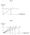
- a relationship between a brightness X of an incident light on a pixel of the light receiving element and a density Y of the pixel in an image captured with the slowest shutter speed (longest exposure period) S0 is expressed by the following equation (1) by normalizing the brightness X and the density Y such that a dynamic range of the density Y is 0 ⁇ Y ⁇ 1.
- Y X (0 ⁇ X ⁇ 1)
- Y 1 (1 ⁇ X)
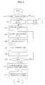
- a relationship between the brightness X and the density Y of the pixel of an image captured with a shutter speed (exposure period) S1 obtained by multiplying the exposure period S0 by (1/A) is expressed by the following equation (2).
- Y X (0 ⁇ X ⁇ A)
- Y 1 (A ⁇ X)
- a relationship between the brightness X and the density Y of the pixel of an image captured with a shutter speed (exposure period) Si obtained by multiplying the exposure period S0 by (1/A i ) is expressed by the following equation (3).
- Y X (0 ⁇ X ⁇ A i )
- Y 1 (A i ⁇ X)
- FIG. 3 A graph showing the above relationships is shown in FIG. 3.
- a stun Z(x) of density of each pixel in N images captured with the exposure period varied stepwise from the longest shutter speed S0 to the shortest shutter speed Sn is expressed by the following set of equations (4);
- Z(X) X + (X/A) + (X/A 2 ) + ... + (X/A N-1 ) (0 ⁇ X ⁇ 1)
- Z(X) 1 + (X/A) + (X/A 2 ) + ... + (X/A N-1 ) (1 ⁇ X ⁇ A)
- Z(X) 1 + 1 + (X/A 2 ) + ... + (X/A N-1 ) (A ⁇ X ⁇ A 2 )
- Z(X) 1 + 1 + 1 + 1 + 1 + ⁇ + (X/A N-1 ) (A N-2 ⁇ X ⁇ A N-1 )
- the equations (4) are represented by a line graph divided into N sections depending on the value of X.
- a section including a certain value X and a section including a value AX as a product of "A" and "X" are consequentially adjacent to each other.
- a value 0.5 of X fulfilling the first equation of the above set of equations (4) in the first section and a value 0.5A of AX fulfils the second equation of the above set of equations (4).
- the following equation (5) is obtained from the above set of equations (4).
- Z(AX) - Z(X) 1 - (X/A N-1 ) (0 ⁇ X ⁇ A N-2 )
- the equation (6) means that Z(X) of the pixel captured with the shutter speed varying from S0 to Si by multiplying (1/A) has characteristics approximated by values obtained by subjecting the brightness X to a logarithm transformation in a range where the brightness of an incident light is smaller than a range obtained by multiplying the dynamic range with the shutter speed S0 by A i .
- the density of each pixel is adjusted according to the equation (7) using the constants B and C.
- the composite density Z' of each pixel to be outputted is obtained according to the equation (7) using the determined values of the constants B and C.
- the constants B and C for adjusting the density are obtained using the maximum value Zmax and the minimum value Zmin of the values of Z(X) for all the pixels.
- the constants B and C may be determined based solely on the maximum value Zmax, solely on the minimum value Zmin, on a mean value Zmean, on a median, on a mode, and on a combination of the mean value Zmean and a standard deviation (or dispersion) of the summed composite value Z(X).
- the minimum value Zmin is set to "0" in the equation (9) to determine the constant C to be "0”
- the constant B is determined according to the equation (8) using the maximum value Zmax and the determined value "0" of the constant C.
- the composite value Z(X) is standardized so that the brightness of incident light from "0" to Zmax is within a range from "0" to "1".
- the ideal maximum value A N-1 is adopted as the minimum value Zmax in the equation (8) to determine the constants B and C according to the equations (8) and (9) using the ideal maximum value A N-1 as the maximum value Zmax and the minimum value Zmin.
- the constant C is determined as the mean value Zmean of the densities
- the constant B is determined according to the equation (8) by setting the maximum value Zmax to the ideal maximum value A N-1 .
- the constant'B is determined according to the equation (9) by setting the minimum value Zmin to "0".
- Zmean-Zmin( 0)
- of a difference between the mean value and the minimum value is compared with an absolute value
- Zmean-Zmin( 0)
- Zmax( AN-1)-Zmean
- Zmean-Zmin( 0)
- Zmax( AN-1) -Zmean
- the constant B is determined using one of the Zmin and Zmax which has a larger difference with respect to the mean value Zmean, to eliminate the saturation of the final image.
- the median or the mode may be used in place of the mean value Zmean.
- the median is obtained by (Zmax-Zmin)/2, and the mode is determined as a median in an range where frequency of the composite value Z(X) is the most in a plurality of ranges obtained by dividing a variation range of the composite value Z(X).
- the mean value Zmean and the standard deviation ⁇ (or dispersion) of the composite value Z(X) are obtained on an assumption that the frequency of the composite value Z(X) has the normal distribution, to determine the constants B and C such that the composite value Z(x) in a certain range is within a range from "0" to "1".
- Zmax Zmean+2 ⁇
- Zmin Zmean-2 ⁇ .
- Zmax Zmean+ ⁇
- Zmin Zmean-2 ⁇ .
- FIG. 4 shows processing for obtaining the composite image using the visual sensor having the two-dimensional image capturing device such as the camera 11 and the light projecting device for projecting the laser beam (spot beam or slit beam) according to the embodiment.
- the visual sensor having the two-dimensional image capturing device such as the camera 11 and the light projecting device for projecting the laser beam (spot beam or slit beam) according to the embodiment.
- Characteristics of the above density transformation are different in both cases. Different values are set to the parameter A for altering magnification of the exposure period in capturing an image in accordance with the case where the laser beam is ON and the case where the laser beam is OFF.
- a value P is set to the parameter A in capturing an image while the laser beam is on and a vale Q is set to the parameter A in capturing an image while the laser beam is off.
- a value Np is set to the number N of times of image capturing while the laser beam is on and a vale Np is set to the number N while the laser beam is off.
- the value Np and the value Np may be the same.
- Step 101 it is determined whether or not a light projection command is issued to the laser excitation power source 14 (Step 101). If the light projection command is issued, the value P for ON state of the laser beam is set to the parameter A, and the value Np for ON state of the laser beam is set to the number N (Step 102). If the light projection command is not issued, the value Q for OFF state of the laser beam is set to the parameter A, and the value Nq for OFF state of the laser beam is set to the number N (Step 103).
- a register for storing a composite image Z of each pixel is set to "0" and an index i is set to "0" (Step 104).
- Step 105 a value of the shutter speed is multiplied by (1/A i ) (Step 105) and an image of the object is captured by the camera 11 with the shutter speed and the captured image is stored in the frame memory (Step 106).
- a density Y of each pixel is added to the register for storing the composite image Z (Step 107)
- the index i is incrementally increased by "1" (Step 108) and it is determined whether or not the index i is equal or greater than the set value of the number N of times of image capturing (Step 109).
- the processing from Steps 105 to Step 109 is repeatedly executed until the index i reaches the set value of the number N.
- each image is captured with the shutter speed obtained by multiplying the shutter speed in the image capturing immediately before each image capturing by (1/A i ).
- the composite image Z' of each pixel for outputting is obtained by the arithmetic operation according to the equation (7) using the composite image value Z of each pixel using the obtained constants B and C (Step 111), to terminate the processing of obtaining the composite image.
- FIG. 5 shows the processing of obtaining the composite image according to a second embodiment.
- the parameter A for altering magnification of the exposure period is changed in accordance with brightness of an image initially captured (a reference image), to obtain the optimum composite image.
- the parameter A for the case where the projection of the laser beam is on and for the case where the projection of the laser beam is off is classified into three ranks in accordance with brightness of the reference image.
- parameter values P1, P2 and P3 in projecting the laser beam and parameter values Q1, Q2 and Q3 in not projecting the laser beam are set in advance.
- the number N of times of image capturing may be changed in accordance with the ranks of images. In this embodiment, however, the value Np in projecting the laser beam and the value Np in not projecting the laser beam are set.
- an image of an object is captured under an predetermined initial condition (Step 201). It is determined whether or not the projection of laser beam is ON or not (Step 202). If the light projection is ON, the density of a part of the captured image of the object receiving the light beam is read (Step 203) and it is determined whether or not the density is equal or lower than a first reference value Ysa1 (Step 204). If the density is equal or lower than the first reference value Ysa1, a first parameter value P1 for the ON state of the light projection is set to the parameter A for altering magnification of the exposure period, and the predetermined value Np for the ON state of the light projection is set to the number N of times of capturing images (Step 205). Then, the same processing as that of Steps 104 and the subsequent Steps in FIG. 4 is executed.
- Step 206 it is further determined whether or not the density Y is equal or greater than a second reference value Ysa2 which is greater than the first reference value Ysa1 (Step 206). If it is determined that the density Y is smaller than the second reference value Ysa2 and thus positioned between the first reference value Ysa1 and the second reference value Ysa2, a second predetermined value P2 is set to the parameter A for altering magnification of the exposure period, and the predetermined value Np for the ON state of light projection is set to the number N of times of image capturing (Step 207). If it is determined that the density Y is equal or greater than the second reference value Ysa2, a third parameter value P3 is set to the parameter A and the predetermined value Np is set to the number N of times of image capturing (Step 208).
- the density Y of whole region of the captured image is read (Step 209) and compared with the first and second reference values Ysb1 and Ysb2 (Step 210, Step 212). If the density Y is not greater than the first reference value Ysb1, a first predetermined value Q1 is set to the parameter A (Step 211). If the density Y is between the first reference value Ysb1 and the second reference value Ysb2, the second predetermined value Q2 is set to the parameter A (Step 213). If the density Y is equal or greater than the second reference value Ysb2, the third predetermined value Q3 is set to the parameter A (Step 214).
- the predetermined value Np for the OFF-state of the light projection is set to the number N of times of image capturing.
- Steps 104 and the subsequent Steps in FIG. 4 After determining the parameter A for altering magnification of the exposure period, the same processing as that of Steps 104 and the subsequent Steps in FIG. 4 is performed, to obtain the final image Z' for output.
- the constants B and C in the equation (7) for obtaining the ultimate composite image Z' are obtained based on the maximum value Zmax and the minimum value Zmin of densities of all pixels.
- the constants B and C may be determined based solely on the maximum value Zmax, solely on the minimum value Zmin, the mean value Zmean, a combination of the mean value Zmean and the standard deviation, for obtaining the final output image Z' using the determined constants B and C.
- the processing of Step 110 is modified to the processing as described.
- the exposure in capturing each image is altered by changing the shutter speed, i.e. the exposure period in the foregoing embodiments.
- a gain of brightness of the image may be changed by changing a gain of amplification of a signal from the camera 11 or a gain of amplification in the camera 11 connected to the camera interface. Since changing the gain of brightness is substantially equal to changing the exposure period, substantially the same effect is obtained by changing the exposure period and by changing the gain of brightness.
- a gain of amplification of a signal from the camera may be successively multiplied by (1/A i ) instead of the processing of multiplying the shutter speed by (1/A i ) in Step 105.
- the predetermined values P, Q, P1-P3 and Q1-Q3 are modified to be appropriate to the amplification of gain.
- a dynamic range of a visual sensor is improved in accordance with various conditions of image capturing such as variation of lightning and posture of an object, so that a visual sensor performs a stable detection not affected by variation of ambience and conditions. Further, a load on a processor for performing arithmetic operations for obtaining a composite image is reduced. Furthermore, the undesirable non-continuousness of density of adjacent pixels of images captured in different conditions, which has been caused in the conventional art, is not produced according to the present invention.
Landscapes
- Engineering & Computer Science (AREA)
- Multimedia (AREA)
- Signal Processing (AREA)
- Image Processing (AREA)
- Studio Devices (AREA)
- Manipulator (AREA)
- Image Input (AREA)
- Transforming Light Signals Into Electric Signals (AREA)
- Mechanical Optical Scanning Systems (AREA)
- Photometry And Measurement Of Optical Pulse Characteristics (AREA)
Abstract
Description
Claims (28)
- A visual sensor comprising:image capturing means for capturing two-dimensional images of an object with controllable exposure periods;reference light projecting means for projecting reference light;storing means for storing parameters for altering the exposure period for capturing two-dimensional images by said image capturing means;image processing means for processing images captured by said image capturing means;reference light control means for controlling ON/OFF of the light projection by said reference light projecting means; andexposure period control means for controlling the exposure period so that said image capturing means captures images with different exposure periods in accordance with ON/OFF state of the light projection using the parameters stored in said storing means.
- A visual sensor according to claim 1, wherein said image processing means includes image composing means for producing a composite image based on densities of each pixel in a plurality of two-dimensional images captured with different exposure periods by said image capturing means.
- A visual sensor according to claim 2, wherein said image composing means obtains a characteristic value representing at least a part of a range of the density of the captured two-dimensional images, and normalize density of the composite image based on the range of density represented by the characteristic value.
- A visual sensor according to claim 3, wherein said characteristic value is one of a maximum value, a minimum value, a mean value, a standard deviation, a dispersion, a median and a mode of brightness of at least a part of the two-dimensional images, or any combination of the maximum value, the minimum value, the mean value, the standard deviation, the dispersion, the median and the mode.
- A visual sensor according to claim 1, wherein said reference light projecting means projects spot light or slit light.
- A visual sensor according to claim 1, wherein said image capturing means comprises a camera having light receiving elements in the form of semiconductor device.
- A visual sensor according to claim 1, wherein said visual sensor is connected to a robot and said reference light control means controls ON/OFF of the light projection by said reference light projecting means in accordance with an operation of the robot or an operation program of the robot.
- A visual sensor comprising:image capturing means for capturing two-dimensional images of an object with controllable exposure periods;reference light projecting means for projecting reference light;storing means for storing parameters for altering the exposure period for capturing two-dimensional images by said image capturing means;image processing means for processing images captured by said image capturing means;reference light control means for controlling ON/OFF of light projection by the reference light projecting means; andexposure period control means for controlling the exposure period in capturing two-dimensional images by said image capturing means in accordance with a density of a part of the two-dimensional image corresponding a lightened part of the object when the light projection is ON, and controlling the exposure period in capturing two-dimensional images by said image capturing means in accordance with a density of a part or a whole area of the two-dimensional image when the light projection is OFF using the parameters stored in said storing means.
- A visual sensor according to claim 8, wherein said image processing means includes image composing means for producing a composite image based on densities of each pixel in a plurality of two-dimensional images captured with different exposure periods by said image capturing means.
- A visual sensor according to claim 9, wherein said image composing means obtains a characteristic value representing at least a part of a range of the density of the captured two-dimensional images, and normalize density of the composite image based on the range of density represented by the characteristic value.
- A visual sensor according to claim 10, wherein said characteristic value is one of a maximum value, a minimum value, a mean value, a standard deviation, a dispersion, a median and a mode of brightness of at least a part of the two-dimensional images, or any combination of the maximum value, the minimum value, the mean value, the standard deviation, the dispersion, the median and the mode.
- A visual sensor according to claim 8, wherein said reference light projecting means projects spot light or slit light.
- A visual sensor according to claim 11, wherein said image capturing means comprises a camera having light receiving elements in the form of semiconductor device.
- A visual sensor according to claim 11, wherein said visual sensor is connected to a robot and said reference light control means controls ON/OFF of the light projection by said reference light projecting means in accordance with an operation of the robot or an operation program of the robot.
- A visual sensor comprising:image capturing means for capturing a two-dimensional image of an object with a controllable gain of brightness;reference light projecting means for projecting reference light;storing means for storing parameters for altering the gain of brightness in capturing two-dimensional images by said image capturing means;image processing means for processing images captured by said image capturing means;reference light control means for controlling ON/OFF of the light projection by said reference light projecting means; andgain control means for controlling the gain of brightness so that said image capturing means captures images with different gains of brightness in accordance with ON/OFF state of the light projection using the parameters stored in said storing means.
- A visual sensor according to claim 15, wherein said image processing means includes image composing means for producing a composite image based on densities of each pixel in a plurality of two-dimensional images captured with different gains of brightness by said image capturing means.
- A visual sensor according to claim 16, wherein said image composing means obtains a characteristic value representing at least a part of a range of the density of the captured two-dimensional images, and normalize density of the composite image based on the range of density represented by the characteristic value.
- A visual sensor according to claim 17, wherein said characteristic value is one of a maximum value, a minimum value, a mean value, a standard deviation, a dispersion, a median and a mode of brightness of at least a part of the two-dimensional images, or any combination of the maximum value, the minimum value, the mean value, the standard deviation, the dispersion, the median and the mode.
- A visual sensor according to claim 15, wherein said reference light projecting means projects spot light or slit light.
- A visual sensor according to claim 15, wherein said image capturing means comprises a camera having light receiving elements in the form of semiconductor device.
- A visual sensor according to claim 15, wherein said visual sensor is connected to a robot and said reference light control means controls ON/OFF of the light projection by said reference light projecting means in accordance with an operation of the robot or an operation program of the robot.
- A visual sensor comprising:image capturing means for capturing a two-dimensional image of an object with a controllable gain of brightness;reference light projecting means for projecting reference light;storing means for storing parameters for altering the gain of brightness in capturing two-dimensional images by said image capturing means;image processing means for processing images captured by said image capturing means;reference light control means for controlling ON/OFF of the light projection by said reference light projecting means; andgain control means for controlling the gain of brightness in capturing two-dimensional images by said image capturing means in accordance with density of a part of the two-dimensional image corresponding a lightened part of the object when the light projection is ON, and controlling the exposure period in capturing two-dimensional images by said image capturing means in accordance with density of a part or a whole area of the two-dimensional image when the light projection is OFF using the parameters stored in said storing means.
- A visual sensor according to claim 22, wherein said image processing means includes image composing means for producing a composite image based on densities of each pixel in a plurality of two-dimensional images captured with different gains of brightness by said image capturing means.
- A visual sensor according to claim 23, wherein said image composing means obtains a characteristic value representing at least a part of a range of the density of the captured two-dimensional images, and normalize density of the composite image based on the range of density represented by the characteristic value.
- A visual sensor according to claim 24, wherein said characteristic value is one of a maximum value, a minimum value, a mean value, a standard deviation, a dispersion, a median and a mode of brightness of at least a part of the two-dimensional images, or any combination of the maximum value, the minimum value, the mean value, the standard deviation, the dispersion, the median and the mode.
- A visual sensor according to claim 22, wherein said reference light projecting means projects spot light or slit light.
- A visual sensor according to claim 22, wherein said image capturing means comprises a camera having light receiving elements in the form of semiconductor device.
- A visual sensor according to claim 22, wherein said visual sensor is connected to a robot and said reference light control means controls ON/OFF of the light projection by said reference light projecting means in accordance with an operation of the robot or an operation program of the robot.
Applications Claiming Priority (2)
| Application Number | Priority Date | Filing Date | Title |
|---|---|---|---|
| JP2001139112 | 2001-05-09 | ||
| JP2001139112A JP3780178B2 (en) | 2001-05-09 | 2001-05-09 | Visual sensor |
Publications (3)
| Publication Number | Publication Date |
|---|---|
| EP1257117A2 true EP1257117A2 (en) | 2002-11-13 |
| EP1257117A3 EP1257117A3 (en) | 2004-12-15 |
| EP1257117B1 EP1257117B1 (en) | 2006-06-14 |
Family
ID=18985944
Family Applications (1)
| Application Number | Title | Priority Date | Filing Date |
|---|---|---|---|
| EP02253239A Expired - Lifetime EP1257117B1 (en) | 2001-05-09 | 2002-05-09 | Visual sensor |
Country Status (4)
| Country | Link |
|---|---|
| US (1) | US7190402B2 (en) |
| EP (1) | EP1257117B1 (en) |
| JP (1) | JP3780178B2 (en) |
| DE (1) | DE60212254T2 (en) |
Cited By (2)
| Publication number | Priority date | Publication date | Assignee | Title |
|---|---|---|---|---|
| WO2008157150A3 (en) * | 2007-06-15 | 2009-02-19 | Micron Technology Inc | Imagers with high speed digital frame transfer and frame processing |
| EP2056591A3 (en) * | 2007-10-31 | 2011-05-18 | Omron Corporation | Image processing apparatus |
Families Citing this family (40)
| Publication number | Priority date | Publication date | Assignee | Title |
|---|---|---|---|---|
| JP4392492B2 (en) * | 2003-06-02 | 2010-01-06 | 国立大学法人静岡大学 | Wide dynamic range image sensor |
| JP2005252711A (en) * | 2004-03-04 | 2005-09-15 | Fuji Photo Film Co Ltd | Imaging system using digital still camera and imaging control method |
| JP4556722B2 (en) | 2004-05-31 | 2010-10-06 | コニカミノルタホールディングス株式会社 | Imaging device |
| JP2005348005A (en) * | 2004-06-02 | 2005-12-15 | Konica Minolta Holdings Inc | Imaging apparatus, imaging system, and imaging system operation program |
| US20060018013A1 (en) * | 2004-07-07 | 2006-01-26 | Yoshimasa Suzuki | Microscope imaging apparatus and biological-specimen examination system |
| US8000837B2 (en) | 2004-10-05 | 2011-08-16 | J&L Group International, Llc | Programmable load forming system, components thereof, and methods of use |
| JP4747065B2 (en) * | 2006-09-29 | 2011-08-10 | 富士通株式会社 | Image generation apparatus, image generation method, and image generation program |
| KR20090028013A (en) * | 2007-09-13 | 2009-03-18 | 삼성전자주식회사 | Drive integrated circuit for display device, display device having same and setting data program method thereof |
| JP2009224971A (en) * | 2008-03-14 | 2009-10-01 | Omron Corp | Image processing device |
| JP4946928B2 (en) * | 2008-03-14 | 2012-06-06 | オムロン株式会社 | Image processing apparatus and image processing method |
| US7999861B2 (en) | 2008-03-14 | 2011-08-16 | Omron Corporation | Image processing apparatus for generating composite image with luminance range optimized for a designated area |
| US20100149393A1 (en) * | 2008-05-22 | 2010-06-17 | Panavision Imaging, Llc | Increasing the resolution of color sub-pixel arrays |
| US8035711B2 (en) * | 2008-05-22 | 2011-10-11 | Panavision Imaging, Llc | Sub-pixel array optical sensor |
| US20090290052A1 (en) * | 2008-05-23 | 2009-11-26 | Panavision Imaging, Llc | Color Pixel Pattern Scheme for High Dynamic Range Optical Sensor |
| JP5181970B2 (en) | 2008-09-25 | 2013-04-10 | オムロン株式会社 | Image processing apparatus and image processing method |
| JP5370056B2 (en) | 2008-11-04 | 2013-12-18 | オムロン株式会社 | Image processing device |
| JP5257375B2 (en) * | 2009-03-13 | 2013-08-07 | オムロン株式会社 | Image processing apparatus and image processing method |
| US20110205384A1 (en) * | 2010-02-24 | 2011-08-25 | Panavision Imaging, Llc | Variable active image area image sensor |
| JP2014050042A (en) * | 2012-09-03 | 2014-03-17 | Toshiba Corp | Image processor and solid-state imaging device |
| US9294686B2 (en) * | 2012-09-25 | 2016-03-22 | Nissan Motor Co., Ltd. | Image capture apparatus and image capture method |
| JP6537231B2 (en) * | 2014-08-11 | 2019-07-03 | キヤノン株式会社 | Image processing apparatus, image processing method and program |
| WO2016172619A1 (en) | 2015-04-23 | 2016-10-27 | Apple Inc. | Digital viewfinder user interface for multiple cameras |
| US10009536B2 (en) | 2016-06-12 | 2018-06-26 | Apple Inc. | Applying a simulated optical effect based on data received from multiple camera sensors |
| DK180859B1 (en) | 2017-06-04 | 2022-05-23 | Apple Inc | USER INTERFACE CAMERA EFFECTS |
| US11112964B2 (en) | 2018-02-09 | 2021-09-07 | Apple Inc. | Media capture lock affordance for graphical user interface |
| US11722764B2 (en) | 2018-05-07 | 2023-08-08 | Apple Inc. | Creative camera |
| DK201870623A1 (en) | 2018-09-11 | 2020-04-15 | Apple Inc. | USER INTERFACES FOR SIMULATED DEPTH EFFECTS |
| US11321857B2 (en) | 2018-09-28 | 2022-05-03 | Apple Inc. | Displaying and editing images with depth information |
| US11128792B2 (en) | 2018-09-28 | 2021-09-21 | Apple Inc. | Capturing and displaying images with multiple focal planes |
| CN111901480B (en) * | 2019-05-06 | 2021-05-28 | 苹果公司 | User interface for capturing and managing visual media |
| US11706521B2 (en) | 2019-05-06 | 2023-07-18 | Apple Inc. | User interfaces for capturing and managing visual media |
| US11770601B2 (en) | 2019-05-06 | 2023-09-26 | Apple Inc. | User interfaces for capturing and managing visual media |
| US11054973B1 (en) | 2020-06-01 | 2021-07-06 | Apple Inc. | User interfaces for managing media |
| US11212449B1 (en) | 2020-09-25 | 2021-12-28 | Apple Inc. | User interfaces for media capture and management |
| US11539876B2 (en) | 2021-04-30 | 2022-12-27 | Apple Inc. | User interfaces for altering visual media |
| US11778339B2 (en) | 2021-04-30 | 2023-10-03 | Apple Inc. | User interfaces for altering visual media |
| US12112024B2 (en) | 2021-06-01 | 2024-10-08 | Apple Inc. | User interfaces for managing media styles |
| US12506953B2 (en) | 2021-12-03 | 2025-12-23 | Apple Inc. | Device, methods, and graphical user interfaces for capturing and displaying media |
| US12401889B2 (en) | 2023-05-05 | 2025-08-26 | Apple Inc. | User interfaces for controlling media capture settings |
| US12602154B2 (en) | 2024-01-18 | 2026-04-14 | Apple Inc. | User interfaces integrating hardware buttons |
Family Cites Families (19)
| Publication number | Priority date | Publication date | Assignee | Title |
|---|---|---|---|---|
| EP0312046B1 (en) * | 1987-10-14 | 1994-07-27 | Hitachi, Ltd. | Apparatus and method for inspecting defect of mounted component with slit light |
| US5264940A (en) * | 1990-10-08 | 1993-11-23 | Olympus Optical Co., Ltd. | Image sensing apparatus having exposure level and dynamic range control circuit |
| JP3394019B2 (en) * | 1990-10-08 | 2003-04-07 | オリンパス光学工業株式会社 | Exposure control circuit of image input device |
| JPH05314253A (en) | 1992-05-12 | 1993-11-26 | Toyota Central Res & Dev Lab Inc | Image converter |
| JPH08279900A (en) | 1995-04-07 | 1996-10-22 | Mitsubishi Electric Corp | Scanner device |
| JPH09311927A (en) | 1996-05-24 | 1997-12-02 | De-Shisu:Kk | Parked vehicle detection device and parked vehicle detection method |
| JPH1021378A (en) | 1996-07-01 | 1998-01-23 | Toyo Commun Equip Co Ltd | Imaging device and imaging method |
| JP3432705B2 (en) | 1997-06-23 | 2003-08-04 | 三菱電機株式会社 | Imaging device |
| JPH1166279A (en) | 1997-08-20 | 1999-03-09 | Canon Inc | Image processing apparatus and image processing method |
| JPH11134505A (en) | 1997-10-31 | 1999-05-21 | Terumo Corp | Image extracting device and image display device using same |
| JPH11167635A (en) | 1997-12-02 | 1999-06-22 | Dainippon Screen Mfg Co Ltd | Plotting deciding device |
| JPH11187199A (en) | 1997-12-17 | 1999-07-09 | Fuji Photo Film Co Ltd | Image input device |
| JPH11218415A (en) | 1998-02-03 | 1999-08-10 | Nikon Corp | Imaging pick up device for three dementional shape measurement |
| JPH11355787A (en) | 1998-06-09 | 1999-12-24 | Konica Corp | Picture processor and picture output device |
| JP4111592B2 (en) * | 1998-06-18 | 2008-07-02 | コニカミノルタセンシング株式会社 | 3D input device |
| JP2000050160A (en) | 1998-08-03 | 2000-02-18 | Ricoh Co Ltd | Image combining apparatus, image combining method, and storage medium storing image combining method |
| JP2000217040A (en) | 1999-01-25 | 2000-08-04 | Nikon Corp | Electronic shutter control device and imaging device using the same |
| JP4292679B2 (en) | 1999-05-10 | 2009-07-08 | コニカミノルタホールディングス株式会社 | Solid-state imaging device |
| JP4186347B2 (en) * | 1999-10-14 | 2008-11-26 | コニカミノルタセンシング株式会社 | Three-dimensional input method and apparatus |
-
2001
- 2001-05-09 JP JP2001139112A patent/JP3780178B2/en not_active Expired - Fee Related
-
2002
- 2002-05-09 EP EP02253239A patent/EP1257117B1/en not_active Expired - Lifetime
- 2002-05-09 US US10/140,998 patent/US7190402B2/en not_active Expired - Lifetime
- 2002-05-09 DE DE60212254T patent/DE60212254T2/en not_active Expired - Lifetime
Cited By (5)
| Publication number | Priority date | Publication date | Assignee | Title |
|---|---|---|---|---|
| WO2008157150A3 (en) * | 2007-06-15 | 2009-02-19 | Micron Technology Inc | Imagers with high speed digital frame transfer and frame processing |
| GB2463222A (en) * | 2007-06-15 | 2010-03-10 | Aptina Imaging Corp | Imagers with high speed digital frame transfer and frame processing |
| US7884871B2 (en) | 2007-06-15 | 2011-02-08 | Aptina Imaging Corporation | Images with high speed digital frame transfer and frame processing |
| EP2056591A3 (en) * | 2007-10-31 | 2011-05-18 | Omron Corporation | Image processing apparatus |
| US8115830B2 (en) | 2007-10-31 | 2012-02-14 | Omron Corporation | Image processing apparatus |
Also Published As
| Publication number | Publication date |
|---|---|
| US7190402B2 (en) | 2007-03-13 |
| US20020167604A1 (en) | 2002-11-14 |
| JP2002334326A (en) | 2002-11-22 |
| DE60212254T2 (en) | 2006-10-05 |
| JP3780178B2 (en) | 2006-05-31 |
| EP1257117B1 (en) | 2006-06-14 |
| DE60212254D1 (en) | 2006-07-27 |
| EP1257117A3 (en) | 2004-12-15 |
Similar Documents
| Publication | Publication Date | Title |
|---|---|---|
| EP1257117B1 (en) | Visual sensor | |
| US8195000B2 (en) | Image pickup apparatus | |
| US8026962B2 (en) | Image synthesizing apparatus and image pickup apparatus with a brightness adjusting processing | |
| US20020171852A1 (en) | System and method for digital image tone mapping using an adaptive sigmoidal function based on perceptual preference guidelines | |
| EP1708490B1 (en) | Image processing device for controlling intensity of noise removal in a screen, image processing program, image processing method, and electronic camera | |
| US9554058B2 (en) | Method, apparatus, and system for generating high dynamic range image | |
| US9398282B2 (en) | Image processing apparatus, control method, and computer-readable medium | |
| CN112783460B (en) | Display control method and device, electronic equipment and readable storage medium | |
| CN113992863B (en) | Automatic exposure method, device, electronic equipment and computer readable storage medium | |
| US8989510B2 (en) | Contrast enhancement using gradation conversion processing | |
| KR100752850B1 (en) | Digital Imaging Device and Method | |
| US20070097228A1 (en) | Image-processing devices, methods, and programs, and electronic cameras and the like comprising same | |
| CN113170040B (en) | Shake correction control device, working method of shake correction control device, storage medium, and imaging device | |
| KR102818837B1 (en) | Method and device for setting optimal exposure of 3d camera | |
| US7702146B2 (en) | Color characterization using color value clipping | |
| US5905533A (en) | Image processing apparatus | |
| JP3494518B2 (en) | Image recognition device using the light section method | |
| CN118102112A (en) | Self-adaptive rapid exposure adjusting method, system, equipment and storage medium | |
| JP2002077619A (en) | Image processing device | |
| TWI698010B (en) | Circuit for controlling image capturing device and associated control method | |
| JP2009044628A (en) | Image processing apparatus and image processing method | |
| CN118828221A (en) | Exposure convergence method and related image processing equipment | |
| KR100277212B1 (en) | Adaptive Digital Signal Processing Unit | |
| US20260038098A1 (en) | Image processing apparatus and method | |
| EP4020972B1 (en) | Image capture device and image capture method |
Legal Events
| Date | Code | Title | Description |
|---|---|---|---|
| PUAI | Public reference made under article 153(3) epc to a published international application that has entered the european phase |
Free format text: ORIGINAL CODE: 0009012 |
|
| AK | Designated contracting states |
Kind code of ref document: A2 Designated state(s): AT BE CH CY DE DK ES FI FR GB GR IE IT LI LU MC NL PT SE TR |
|
| AX | Request for extension of the european patent |
Free format text: AL;LT;LV;MK;RO;SI |
|
| PUAL | Search report despatched |
Free format text: ORIGINAL CODE: 0009013 |
|
| AK | Designated contracting states |
Kind code of ref document: A3 Designated state(s): AT BE CH CY DE DK ES FI FR GB GR IE IT LI LU MC NL PT SE TR |
|
| AX | Request for extension of the european patent |
Extension state: AL LT LV MK RO SI |
|
| 17P | Request for examination filed |
Effective date: 20050309 |
|
| 17Q | First examination report despatched |
Effective date: 20050601 |
|
| AKX | Designation fees paid |
Designated state(s): DE |
|
| GRAP | Despatch of communication of intention to grant a patent |
Free format text: ORIGINAL CODE: EPIDOSNIGR1 |
|
| GRAS | Grant fee paid |
Free format text: ORIGINAL CODE: EPIDOSNIGR3 |
|
| GRAA | (expected) grant |
Free format text: ORIGINAL CODE: 0009210 |
|
| AK | Designated contracting states |
Kind code of ref document: B1 Designated state(s): DE |
|
| REF | Corresponds to: |
Ref document number: 60212254 Country of ref document: DE Date of ref document: 20060727 Kind code of ref document: P |
|
| PLBE | No opposition filed within time limit |
Free format text: ORIGINAL CODE: 0009261 |
|
| STAA | Information on the status of an ep patent application or granted ep patent |
Free format text: STATUS: NO OPPOSITION FILED WITHIN TIME LIMIT |
|
| 26N | No opposition filed |
Effective date: 20070315 |
|
| REG | Reference to a national code |
Ref country code: DE Ref legal event code: R082 Ref document number: 60212254 Country of ref document: DE Representative=s name: HASELTINE LAKE LLP, DE |
|
| PGFP | Annual fee paid to national office [announced via postgrant information from national office to epo] |
Ref country code: DE Payment date: 20180424 Year of fee payment: 17 |
|
| REG | Reference to a national code |
Ref country code: DE Ref legal event code: R119 Ref document number: 60212254 Country of ref document: DE |
|
| PG25 | Lapsed in a contracting state [announced via postgrant information from national office to epo] |
Ref country code: DE Free format text: LAPSE BECAUSE OF NON-PAYMENT OF DUE FEES Effective date: 20191203 |