EP1257080A2 - Encoding/decoding apparatus and method in a CDMA mobile communication system - Google Patents
Encoding/decoding apparatus and method in a CDMA mobile communication system Download PDFInfo
- Publication number
- EP1257080A2 EP1257080A2 EP02010614A EP02010614A EP1257080A2 EP 1257080 A2 EP1257080 A2 EP 1257080A2 EP 02010614 A EP02010614 A EP 02010614A EP 02010614 A EP02010614 A EP 02010614A EP 1257080 A2 EP1257080 A2 EP 1257080A2
- Authority
- EP
- European Patent Office
- Prior art keywords
- input information
- symbol
- coded
- positions
- information bits
- Prior art date
- Legal status (The legal status is an assumption and is not a legal conclusion. Google has not performed a legal analysis and makes no representation as to the accuracy of the status listed.)
- Granted
Links
Images






Classifications
-
- H—ELECTRICITY
- H03—ELECTRONIC CIRCUITRY
- H03M—CODING; DECODING; CODE CONVERSION IN GENERAL
- H03M13/00—Coding, decoding or code conversion, for error detection or error correction; Coding theory basic assumptions; Coding bounds; Error probability evaluation methods; Channel models; Simulation or testing of codes
-
- H—ELECTRICITY
- H04—ELECTRIC COMMUNICATION TECHNIQUE
- H04L—TRANSMISSION OF DIGITAL INFORMATION, e.g. TELEGRAPHIC COMMUNICATION
- H04L1/00—Arrangements for detecting or preventing errors in the information received
- H04L1/004—Arrangements for detecting or preventing errors in the information received by using forward error control
- H04L1/0056—Systems characterized by the type of code used
- H04L1/0067—Rate matching
- H04L1/0068—Rate matching by puncturing
- H04L1/0069—Puncturing patterns
-
- H—ELECTRICITY
- H04—ELECTRIC COMMUNICATION TECHNIQUE
- H04L—TRANSMISSION OF DIGITAL INFORMATION, e.g. TELEGRAPHIC COMMUNICATION
- H04L1/00—Arrangements for detecting or preventing errors in the information received
- H04L1/004—Arrangements for detecting or preventing errors in the information received by using forward error control
- H04L1/0041—Arrangements at the transmitter end
- H04L1/0043—Realisations of complexity reduction techniques, e.g. use of look-up tables
-
- H—ELECTRICITY
- H04—ELECTRIC COMMUNICATION TECHNIQUE
- H04L—TRANSMISSION OF DIGITAL INFORMATION, e.g. TELEGRAPHIC COMMUNICATION
- H04L1/00—Arrangements for detecting or preventing errors in the information received
- H04L1/004—Arrangements for detecting or preventing errors in the information received by using forward error control
- H04L1/0056—Systems characterized by the type of code used
- H04L1/0057—Block codes
-
- H—ELECTRICITY
- H04—ELECTRIC COMMUNICATION TECHNIQUE
- H04L—TRANSMISSION OF DIGITAL INFORMATION, e.g. TELEGRAPHIC COMMUNICATION
- H04L1/00—Arrangements for detecting or preventing errors in the information received
- H04L1/004—Arrangements for detecting or preventing errors in the information received by using forward error control
- H04L1/0072—Error control for data other than payload data, e.g. control data
-
- H—ELECTRICITY
- H04—ELECTRIC COMMUNICATION TECHNIQUE
- H04L—TRANSMISSION OF DIGITAL INFORMATION, e.g. TELEGRAPHIC COMMUNICATION
- H04L1/00—Arrangements for detecting or preventing errors in the information received
- H04L1/0001—Systems modifying transmission characteristics according to link quality, e.g. power backoff
- H04L1/0002—Systems modifying transmission characteristics according to link quality, e.g. power backoff by adapting the transmission rate
-
- H—ELECTRICITY
- H04—ELECTRIC COMMUNICATION TECHNIQUE
- H04L—TRANSMISSION OF DIGITAL INFORMATION, e.g. TELEGRAPHIC COMMUNICATION
- H04L1/00—Arrangements for detecting or preventing errors in the information received
- H04L1/08—Arrangements for detecting or preventing errors in the information received by repeating transmission, e.g. Verdan system
Definitions
- the present invention relates generally to an encoding/decoding apparatus and method in a CDMA (Code Division Multiple Access) mobile communication system, and in particular, to an apparatus and method for transmitting a reverse rate indicator channel (R-RICH) used in a synchronous mobile communication system.
- CDMA Code Division Multiple Access
- R-RICH reverse rate indicator channel
- a reverse supplemental channel fundamentally supports a variable rate transmission scheme.
- a mobile station varies its transmission rate arbitrarily.
- a change in a data rate causes a change in a code rate of error correcting codes used in constructing a frame, a symbol repetition frequency, and a length and type of Walsh codes for spreading. Therefore, the mobile station should inform a base station of a data rate of the currently transmitted reverse supplemental channel, so that a base station receiver can correctly receive the reverse supplemental channel.
- a channel defined for this use is called a reverse rate indicator channel (R-RICH).
- the number of kinds of data rates that can be transmitted by the mobile station over the reverse supplemental channel depends upon the number of reverse supplemental channels that can be simultaneously used by the mobile station.
- the number of the reverse supplemental channels is determined by the base station considering an amount of data to be transmitted over a reverse link during call setup, and then reported to the mobile station. Therefore, the number of information bits transmitted over the reverse rate indictor channel varies depending on the number of the reverse supplemental channels. That is, when the number of the reverse supplemental channels is 1, the mobile station informs a reverse data rate using 4 bits. Further, when the number of the reverse supplemental channels is 2, the mobile station informs the reverse data rate using 7 bits.
- the mobile station Since the number of the reverse supplemental channels that can be simultaneously used by the mobile station cannot be changed until a separate command is received from the base station, the mobile station transmits either 4-bit information or 7-bit information over the reverse rate indicator channel. That is, the mobile station will never transmit both the 4-bit information and the 7-bit information at the same time.
- a (24,4) or (24,7) code is defined as an error correcting code to be used in the reverse rate indicator channel.
- R-RICH reverse rate indicator channel
- the number of bits transmitted for transmission of the reverse rates depends upon only the number of the reverse supplemental channels. That is, the number of different data rates that can be transmitted by the mobile station over the reverse supplemental channel is not considered in determining the number of bits transmitted over the reverse supplemental channel.
- the mobile station may transmit more bits than actually required bits. For example, when the number of reverse supplemental channels is 1 and the number of different (or "kinds of") data rates that can be transmitted by the mobile station over the reverse supplemental channel is 4, the minimum number of bits needed for transmitting the data rates is 2.
- the minimum number of the bits required for transmitting the data rates is 4.
- the number of the bits transmitted over the reverse rate indicator channel is larger than needed. Transmitting unnecessarily large number of the bits over the reverse rate indicator channel causes an increase in a code rate of an encoder, making it difficult to apply an optimal encoding method.
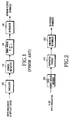
- FIG. 1 illustrates a structure of an R-RICH transmitter.
- an encoder 100 encodes a 4-bit or 7-bit input rate indicator and outputs 24 coded symbols.
- a symbol repeater 110 repeats 16 times the 24 coded symbols provided from the encoder 100.
- a signal mapper 120 performs signal mapping on the coded symbols output from the symbol repeater 110 by mapping 0 to 1 and 1 to -1.
- a spreader 130 spreads the signal-mapped symbols.
- the rate indicator has 4 bits or 7 bits, and encoded into 24 coded symbols before transmission.
- the rate indicator may incorrectly indicate the code rate of the corresponding reverse supplemental channel, the symbol repetition frequency, and the length and type of the spread Walsh code.
- the receiver cannot correctly analyze the reverse supplemental channel. Therefore, the rate indicator should be encoded by a (24,4) or (24,7) encoder having good performance.
- the rate indicator should be decoded as fast as possible in order to analyze the corresponding supplemental channel.
- an encoding method in a mobile communication system for receiving 1 to 7 input information bits and outputting a coded symbol stream having 24 coded symbols depending on a predetermined number of the input information bits.
- the encoding method comprises (a) encoding the input information bits with Walsh codes W1, W2, W4, W8 and W16, and masks M1 and M2, all having a predetermined length, and outputting a coded symbol stream having a predetermined number of coded symbols; (b) previously determining a plurality of sets of puncturing positions corresponding to each of possible numbers of the input information bits, and determining puncturing positions corresponding to the number of the input information bits among the previously determined sets of the puncturing positions; and (c) puncturing coded symbols in the determined puncturing positions from the coded symbol stream having the predetermined number of coded symbols, and outputting the coded symbol stream having 24 coded symbols.
- an encoding apparatus in a mobile communication system, for receiving 1 to 7 input information bits and outputting a coded symbol stream having 24 coded symbols depending on a predetermined number of input information bits.
- the encoding apparatus comprises a Walsh code generator for generating 5 different Walsh codes W1, W2, W4, W8 and W16 having a predetermined length; a mask generator for generating 2 different masks M1 and M2; a plurality of multipliers for multiplying the input information bits by the Walsh codes W1, W2, W4, W8 and W16 and the masks M1 and M2 on a one-to-one basis and outputting a predetermined number of coded symbol streams; an XOR operator for XORing the coded symbol streams from the multipliers and outputting one coded symbol stream; and a puncturer for determining puncturing positions corresponding to the number of the input information bits among a plurality of sets of puncturing positions corresponding to each of possible numbers of the input information bits, puncturing coded symbols in the
- a decoding method in a mobile communication system for receiving a coded symbol stream having 24 coded symbols and outputting 1 to 7 input information bits from the coded symbol stream.
- the decoding method comprises determining puncturing positions according to length information of the input information bits; inserting zero (0) in the determined puncturing positions for the coded symbol stream and outputting a coded symbol stream having a predetermined number of coded symbols; measuring correlation values of the zero-inserted coded symbol stream by the Walsh codes W1, W2, W4, W8 and W16 and the masks M1 and M2 having a length determined depending on the length information of the input information bits; and outputting the input information bits from the measured correlation values.
- a decoding apparatus in a mobile communication system, for receiving a coded symbol stream having 24 coded symbols and outputting 1 to 7 input information bits from the coded symbol stream.
- the decoding apparatus comprises a zero inserter for inserting zero (0) in different puncturing positions of the coded symbol stream depending on length information of the input information bits; a correlation measurer for measuring correlation values of the zero-inserted coded symbol stream by the Walsh codes W1, W2, W4, W8 and W16 and the masks M1 and M2 having a length determined depending on the length information of the input information bits; and a correlation comparator for outputting the input information bits from the measured correlation values.
- Hamming distance distribution for codewords of the error correcting codes serve as a measure indicating the performance of linear error correcting codes.
- the "Hamming distance” indicates the number of non-zero symbols in a codeword. That is, for a certain codeword '0111', the number of 1's included in the codeword is 3, so the Hamming distance is 3.
- the least value among the Hamming distance values is called a "minimum distance d min ", and an increase in the minimum distance of the codeword improves the error correcting performance of the error correcting codes.
- the "optimal code” means a code having the optimal error correcting performance.
- FIG. 10 illustrates a structure of an R-RICH transmitter for minimizing the number of bits assigned to a rate indicator according to an embodiment of the present invention.
- an encoder 1200 encodes a k-bit rate indicator and outputs a coded symbol stream comprised of 24 coded symbols.
- the number k of the bits assigned to the rate indicator is determined depending on the number of kinds of the data rates that can be transmitted by the mobile station over the reverse supplemental channel.
- the encoder 1200 serves as one of (24,1) encoder, (24,2) encoder, (24,3) encoder, (24,4) encoder, (24,5) encoder, (24,6) encoder and (24,7) encoder depending on the number k of input bits.
- a symbol repeater 1210 repeats 16 times the 24 coded symbols provided from the encoder 1200.
- a signal mapper 1220 performs signal mapping on the coded symbols output from the symbol repeater 1210 by mapping 0 to 1 and 1 to -1.
- a spreader 1230 spreads the signal-mapped symbols.
- minimizing the number of bits assigned to the rate indicator causes a decrease in a code rate of the encoder, thereby improving performance of the rate indicator channel.
- the encoder for encoding the rate indicator channel includes (24,1) encoder, (24,2) encoder, (24,3) encoder, (24,4) encoder, (24,5) encoder, (24,6) encoder and (24,7) encoder.
- an optimal (24,1) linear encoder with 1 input bit and 24 output bits has a maximum distance 24
- an optimal (24,2) linear encoder with 2 input bits and 24 output bits has a maximum distance 16
- an optimal (24,3) linear encoder with 3 input bits and 24 output bits has a maximum distance 13
- an optimal (24,4) linear encoder with 4 input bits and 24 output bits has a maximum distance 12
- an optimal (24,5) linear encoder with 5 input bits and 24 output bits has a maximum distance 12
- an optimal (24,6) linear encoder with 6 input bits and 24 output bits has a maximum distance 10
- an optimal (24,7) linear encoder with 7 input bits and 24 output bits has a maximum distance 10.
- the (24,1) encoder to the (24,7) encoder for encoding the rate indicator will be described in turn.
- the (24,1) encoder provided by the invention is constructed to generate an optimal (24,1) code by repeating a (2,1) Reed-Muller code 32 times and then puncturing 40 symbols from the repeated code.
- an optimal codeword in terms of error correcting performance by utilizing a method of puncturing a first order Reed-Muller code according to an embodiment of the present invention. It will be assumed that the embodiment of the present invention generates the error correcting codes using the Reed-Muller code. Also, it is possible to minimize the hardware complexity by minimizing a length of the Reed-Muller code before puncturing.
- the (24,1) encoder outputs coded symbols of length 24 by repeating 32 times 2 coded symbols output from a (2,1) Reed-Muller code generator and then puncturing 40 symbols from the repeated coded symbols.
- a change in the puncturing positions where the 40 symbols are punctured from the repeated coded symbols of length 64 causes a change in the minimum distance d min of the codeword. Therefore, in order to make a (24,1) encoder with excellent error correcting performance in the coded symbols of length 64, it is important to calculate the puncturing positions where the largest minimum distance can be obtained.
- the simplest puncturing pattern for the 40 puncturing positions needed to generate an optimal (24,1) linear code is ⁇ even-numbered puncturing positions and positions 1,3,5,7,9,11,13,15 ⁇ .
- a transmitter and a receiver of the mobile communication system transmitting the 1 information bit using the encoding/decoding method according to the present invention previously exchange or otherwise pre-store the 40 puncturing positions.
- the puncturing positions are generally defined in a communication protocol.
- the transmitter may previously provide information on the puncturing positions.
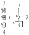
- FIG. 11 illustrates a structure of an encoder included in a transmitter according to an embodiment of the present invention.
- one input information bit a0 is applied to a (2,1) Reed-Muller encoder 1300.
- the input information bit a0 constitutes a rate indicator.
- the Reed-Muller encoder 1300 encodes the input information bit a0 and outputs coded symbols of length 2 (or a coded symbol stream).
- the coded symbols constitute a Reed-Muller code.
- the 2 coded symbols are provided to a repeater 1310.
- the repeater 1310 outputs 64 coded symbols by repeating the received 2 coded symbols 32 times.
- a puncturer 1320 punctures coded symbols in the 40 optimal puncturing positions from the received 64 coded symbols, and outputs coded symbols of length 24.
- the puncturer 1320 punctures the even-numbered symbols and the 1 st , 3 rd , 5 th , 7 th , 9 th , 11 th , 13 th and 15 th symbols in the above-stated 40 optimal puncturing positions from the received 64 coded symbols, and then outputs 24 coded symbols.
- a general code theory defines a generating matrix in order to show a mapping relation between the input information and the coded symbols.
- a generating matrix for a final (24,1) encoder is represented by
- the generating matrix of Equation 1 selects 24 symbols in a first row if the 1-bit input signal is 1, and selects no symbol if the 1-bit input signal is 0. When no symbol is selected, the symbol stream is comprised of 24 0's.
- FIG. 12 illustrates a (24,1) encoder based on the above generating matrix.
- an input information bit a0 having a value of 0 or 1 is applied to a multiplier 1410.
- the multiplier 1410 then multiplies the symbols of the symbol stream R1 by the input information bit a0, and outputs a coded symbol stream of length 24.
- the (24,2) encoder provided by the invention is constructed to generate an optimal (24,2) code by repeating a (4,2) Reed-Muller code 8 times and then puncturing 8 symbols from the repeated code.
- an optimal codeword in terms of error correcting performance by utilizing a method of puncturing a first order Reed-Muller code according to an embodiment of the present invention. It will be assumed that the embodiment of the present invention generates the error correcting codes using the Reed-Muller code. Also, it is possible to minimize the hardware complexity by minimizing a length of the Reed-Muller code before puncturing.
- the (24,2) encoder outputs coded symbols of length 24 by repeating 8 times 4 coded symbols output from a (4,2) Reed-Muller code generator and then puncturing 8 symbols from the repeated coded symbols.
- a change in the puncturing positions where the 8 symbols are punctured from the repeated coded symbols of length 32 causes a change in the minimum distance d min of the codeword. Therefore, in order to make a (24,2) encoder with excellent error correcting performance in the coded symbols of length 32, it is important to calculate the puncturing positions where the largest minimum distance can be obtained.
- the simplest puncturing pattern for the 8 puncturing positions needed to generate an optimal (24,2) linear code is ⁇ 0,4,8,12,16,20,24,28 ⁇ .
- a transmitter and a receiver of the mobile communication system transmitting 2 information bits using the encoding/decoding method according to the present invention previously exchange or otherwise pre-store the 8 puncturing positions.
- the puncturing positions are generally defined in a communication protocol.
- the transmitter may previously provide information on the puncturing positions.
- FIG. 13 illustrates a structure of an encoder included in a transmitter according to an embodiment of the present invention.
- 2 input information bits a0 and a1 are applied to a (4,2) Reed-Muller encoder 1500.
- the input information bits a0 and a1 constitute a rate indicator.
- the Reed-Muller encoder 1500 encodes the input information bits a0 and a1, and outputs coded symbols of length 4 (or a coded symbol stream).
- the coded symbols constitute a Reed-Muller code.
- the 4 coded symbols are provided to a repeater 1510.
- the repeater 1510 outputs 32 coded symbols by repeating 8 times the received coded symbols of length 4.
- a puncturer 1520 punctures 0 th , 4 th , 8 th , 12 th , 16 th , 20 th , 24 th and 28 th symbols in the 8 optimal puncturing positions from the 32 coded symbols, and thus outputs 24 coded symbols.
- a general code theory defines a generating matrix in order to show a mapping relation between the input information and the coded symbols.
- a generating matrix for a final (24,2) encoder is represented by
- the generating matrix of Equation 2 selects 24 symbols in a first row if the first input information bit of the 2 input information bits is 1, and selects no symbol if the first input information bit is 0.
- the generating matrix selects 24 symbols in a second row if the second input information bit of the 2 input information bits is 1, and selects no symbols if the second input information bit is 0.
- a coded symbol stream for the input information bits is generated by XORing all the selected streams in a symbol unit.
- FIG. 14 illustrates a (24,2) encoder based on the above generating matrix.
- the input information bit a0 is applied to a multiplier 1620
- the input information bit a1 is applied to a multiplier 1622, respectively.
- the multiplier 1620 then multiplies the symbols of the symbol stream R1 by the input information bit a0, and outputs a symbol stream of length 24 to an XOR operator 1640.
- the multiplier 1622 multiplies the symbols of the symbol stream R2 by the input information bit a1, and outputs a symbol stream of length 24 to the XOR operator 1640.
- the XOR operator 1640 then XORs the received 2 symbol streams of length 24 in a symbol unit, and outputs a coded symbol stream of length 24.
- the (24,3) encoder provided by the invention is constructed to generate an optimal (24,3) code by repeating a (8,3) Reed-Muller code 4 times and then puncturing 8 symbols from the repeated code.
- the (24,3) code it is possible not only to minimize hardware complexity but also to create an optimal codeword in terms of error correcting performance by utilizing a method of puncturing a first order Reed-Muller code according to an embodiment of the present invention. It will be assumed that the embodiment of the present invention generates the error correcting codes using the Reed-Muller code. Also, it is possible to minimize the hardware complexity by minimizing a length of the Reed-Muller code before puncturing.
- the (24,3) encoder outputs coded symbols of length 24 by repeating 4 times 8 coded symbols output from a (8,3) Reed-Muller code generator and then puncturing 8 symbols from the repeated coded symbols.
- a change in the puncturing positions where the 8 symbols are punctured from the coded symbols of length 32 causes a change in the minimum distance d min of the codeword. Therefore, in order to make a (24,3) encoder with excellent error correcting performance in the coded symbols of length 32, it is important to calculate the puncturing positions where the largest minimum distance can be obtained.
- the simplest puncturing pattern for the 8 puncturing positions needed to generate an optimal (24,3) linear code is ⁇ 0,3,5,6,7,8,16,24 ⁇ .
- a transmitter and a receiver of the mobile communication system transmitting 3 information bits using the encoding/decoding method according to the present invention previously exhange or otherwise pre-store the 8 puncturing positions.
- the puncturing positions are generally defined in a communication protocol.
- the transmitter may previously provide information on the puncturing positions.
- FIG. 15 illustrates a structure of an encoder included in a transmitter according to an embodiment of the present invention.
- 3 input information bits a0, a1 and a2 are applied to a (8,3) Reed-Muller encoder 1700.
- the input information bits a0, a1 and a2 constitute a rate indicator.
- the Reed-Muller encoder 1700 encodes the input information bits a0, a1, and a2, and outputs coded symbols of length 8 (or a coded symbol stream).
- the coded symbols constitute a Reed-Muller code.
- the 8 coded symbols are provided to a repeater 1710.
- the repeater 1710 outputs 32 coded symbols by repeating 4 times the received coded symbols of length 8.
- a puncturer 1720 punctures 0 th , 3 rd , 5 th , 6 th , 7 th , 8 th , 16 th and 24 th symbols in the 8 optimal puncturing positions from the 32 coded symbols, and outputs 24 coded symbols.
- a general code theory defines a generating matrix in order to show a mapping relation between the input information and the coded symbols.
- a generating matrix for a final (24,3) encoder is represented by
- the generating matrix of Equation 3 selects 24 symbols in a first row if the first input information bit among the 3 input information bits is 1, and selects no symbol if the first input information bit is 0.
- the generating matrix selects 24 symbols in a second row if the second input information bit among the 3 input information bits is 1, and selects no symbols if the second input information bit is 0. Further, the generating matrix selects 24 symbols in a third row if the third input information bit among the 3 input information bits is 1, and selects no symbols if the third input information bit is 0.
- a coded symbol stream for the input information bits is generated by XORing all the selected streams in a symbol unit.
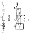
- FIG. 16 illustrates a (24,3) encoder based on the above generating matrix.
- the input information bit a0 is applied to a multiplier 1820
- the input information bit a1 is applied to a multiplier 1822
- the input information bit a2 is applied to a multiplier 1824, respectively.
- a signal generator 1800 provides three symbol streams constituting the generating matrix, stored in a memory, to the associated multipliers.
- the multiplier 1820 then multiplies the symbols of the symbol stream R1 by the input information bit a0, and outputs a symbol stream of length 24 to an XOR operator 1840.
- the multiplier 1822 multiplies the symbols of the symbol stream R2 by the input information bit a1, and outputs a symbol stream of length 24 to the XOR operator 1840.
- the multiplier 1824 multiplies the symbols of the symbol stream R3 by the input information bit a2, and outputs a symbol stream of length 24 to the XOR operator 1840.
- the XOR operator 1840 then XORs the received 3 symbol streams of length 24 in a symbol unit, and outputs a coded symbol stream of length 24.
- the (24,4) encoder provided by the invention is constructed to generate an optimal (24,4) code by repeating a (16,4) Reed-Muller code 4 times and then puncturing 8 symbols from the repeated code.
- an optimal codeword in terms of error correcting performance by utilizing a method of puncturing a first order Reed-Muller code according to an embodiment of the present invention.
- the (24,4) encoder outputs coded symbols of length 24 by repeating twice 16 coded symbols output from a (16,4) Reed-Muller code generator and then puncturing 8 symbols from the repeated coded symbols.
- a change in the puncturing positions where the 8 symbols are punctured from the coded symbols of length 32 causes a change in the minimum distance d min of the codeword. Therefore, in order to make a (24,4) encoder with excellent error correcting performance in the coded symbols of length 32, it is important to calculate the puncturing positions where the largest minimum distance can be obtained.
- the simplest puncturing pattern for the 8 puncturing positions needed to generate an optimal (24,4) linear code is ⁇ 0,1,2,3,4,5,6,16 ⁇ .
- a transmitter and a receiver of the mobile communication system transmitting 4 information bits using the encoding/decoding method according to the present invention should previously agree on the 8 puncturing positions.
- the puncturing positions are generally defined in a communication protocol.
- the transmitter may previously provide information on the puncturing positions.
- FIG. 2 illustrates a structure of an encoder included in a transmitter according to an embodiment of the present invention.
- 4 input information bits a0, a1, a2 and a3 are applied to a (16,4) Reed-Muller encoder 200.
- the input information bits a0, a1, a2 and a3 constitute a rate indicator.
- the Reed-Muller encoder 200 encodes the input information bits a0, a1, a2 and a3, and outputs coded symbols of length 16 (or a coded symbol stream).
- the coded symbols constitute a Reed-Muller code.
- the 16 coded symbols are provided to a repeater 210.
- the repeater 210 outputs 32 coded symbols by repeating twice the received coded symbols of length 16.
- a puncturer 220 punctures 0 th , 1 st , 2 nd 3 rd , 4 th , 5 th , 6 th and 16 th symbols in the 8 optimal puncturing positions from the 32 coded symbols, and outputs 24 coded symbols.
- a general code theory defines a generating matrix in order to show a mapping relation between the input information and the coded symbols.
- a generating matrix for a final (24,4) encoder is represented by
- the generating matrix of Equation 4 selects 24 symbols in a first row if the first input information bit among the 4 input information bits is 1, and selects no symbol if the first input information bit is 0.
- the generating matrix selects 24 symbols in a second row if the second input information bit among the 4 input information bits is 1, and selects no symbols if the second input information bit is 0.
- the generating matrix selects 24 symbols in a third row if the third input information bit among the 4 input information bits is 1, and selects no symbols if the third input information bit is 0.
- the generating matrix selects 24 symbols in a fourth row if the fourth input information bit among the 4 input information bits is 1, and selects no symbols if the fourth input information bit is 0.
- a coded symbol stream for the input information bits is generated by XORing all the selected streams in a symbol unit.
- FIG. 7 illustrates a (24,4) encoder based on the above generating matrix.
- the input information bit a0 is applied to a multiplier 920
- the input information bit a1 is applied to a multiplier 922
- the input information bit a2 is applied to a multiplier 924
- the input information bit a3 is applied to a multiplier 926, respectively.
- a signal generator 900 provides 4 symbol streams R1-R4 constituting the generating matrix, stored in a memory, to the multipliers 920-926, respectively.
- the multiplier 924 multiplies the symbols of the symbol stream R3 by the input information bit a2, and outputs a symbol stream of length 24 to the XOR operator 940.
- the multiplier 926 multiplies the symbols of the symbol stream R4 by the input information bit a3, and outputs a symbol stream of length 24 to the XOR operator 940.
- the XOR operator 940 then XORs the 4 symbol streams of length 24 in a symbol unit, and outputs a coded symbol stream of length 24.
- the (24,5) encoder provided by the invention is constructed to generate an optimal (24,5) code by puncturing 8 symbols from a (32,5) first order Reed-Muller code.
- the (24,5) code it is possible not only to minimize hardware complexity but also to create an optimal codeword in terms of error correcting performance by utilizing a method of puncturing a first order Reed-Muller code according to an embodiment of the present invention. It will be assumed that the embodiment of the present invention generates the error correcting codes using the Reed-Muller code. Also, it is possible to minimize the hardware complexity by minimizing a length of the Reed-Muller code before puncturing.
- the (24,5) encoder outputs coded symbols of length 24 by outputting 32 coded symbols generated by a (32,5) Reed-Muller code generator and then puncturing 8 symbols from the 32 coded symbols.
- a change in the puncturing positions where the 8 symbols are punctured from the coded symbols of length 32 causes a change in the minimum distance d min of the codeword. Therefore, in order to make a (24,5) encoder with excellent error correcting performance in the (32,5) first order Reed-Muller code, it is important to calculate the puncturing positions where the largest minimum distance can be obtained.
- the simplest puncturing pattern for the 8 puncturing positions needed to generate an optimal (24,5) linear code is ⁇ 0,1,2,3,4,5,6,7 ⁇ .
- a transmitter and a receiver of the mobile communication system transmitting 5 information bits using the encoding/decoding method according to the present invention previously exchange or otherwise pre-store the 8 puncturing positions.
- the puncturing positions are generally defined in a communication protocol.
- the transmitter may previously provide information on the puncturing positions.
- FIG. 17 illustrates a structure of an encoder included in a transmitter according to an embodiment of the present invention.
- 5 input information bits a0, a1, a2, a3 and a4 are applied to a (32,5) Reed-Muller encoder 1900.
- the input information bits a0, a1, a2, a3 and a4 constitute a rate indicator.
- the Reed-Muller encoder 1900 encodes the input information bits a0, a1, a2, a3 and a4, and outputs coded symbols of length 32 (or a coded symbol stream).
- a punctures 1920 punctures 0 th , 1 st , 2 nd 3 rd , 4 th , 5 th , 6 th and 7 th symbols in the 8 optimal puncturing positions from the 32 coded symbols, and outputs 24 coded symbols.
- a general code theory defines a generating matrix in order to show a mapping relation between the input information and the coded symbols.
- a generating matrix for a final (24,5) encoder is represented by
- the generating matrix of Equation 5 selects 24 symbols in a first row if the first input information bit among the 5 input information bits is 1, and selects no symbol if the first input information bit is 0.
- the generating matrix selects 24 symbols in a second row if the second input information bit among the 5 input information bits is 1, and selects no symbols if the second input information bit is 0.
- the generating matrix selects 24 symbols in a third row if the third input information bit among the 5 input information bits is 1, and selects no symbols if the third input information bit is 0.
- the generating matrix selects 24 symbols in a fourth row if the fourth input information bit among the 5 input information bits is 1, and selects no symbols if the fourth input information bit is 0.
- the generating matrix selects 24 symbols in a fifth row if the fifth input information bit among the 5 input information bits is 1, and selects no symbols if the fifth input information bit is 0.
- a coded symbol stream for the input information bits is generated by XORing all the selected streams in a symbol unit.
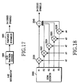
- FIG. 18 illustrates a (24,5) encoder based on the above generating matrix.
- the input information bit a0 is applied to a multiplier 2020
- the input information bit a1 is applied to a multiplier 2022
- the input information bit a2 is applied to a multiplier 2024
- the input information bit a3 is applied to a multiplier 2026
- the input information bit a4 is applied to a multiplier 2028, respectively.
- a signal generator 2000 provides 5 symbol streams R1-R5 constituting the generating matrix, stored in a memory, to the multipliers 2020-2026, respectively.
- the multiplier 2022 multiplies the symbols of the symbol stream R2 by the input information bit a1, and outputs a symbol stream of length 24 to the XOR operator 2040.
- the multiplier 2024 multiplies the symbols of the symbol stream R3 by the input information bit a2, and outputs a symbol stream of length 24 to the XOR operator 2040.
- the multiplier 2026 multiplies the symbols of the symbol stream R4 by the input information bit a3, and outputs a symbol stream of length 24 to the XOR operator 2040.
- the multiplier 2028 multiplies the symbols of the symbol stream R5 by the input information bit a4, and outputs a symbol stream of length 24 to the XOR operator 2040.
- the XOR operator 2040 then XORs the 5 symbol streams of length 24 in a symbol unit, and outputs a coded symbol stream of length 24.
- the (24,6) encoder provided by the invention is constructed to generate an optimal (24,6) code by puncturing 8 symbols from an extended orthogonal code obtained by extending a codeword using one mask function for a (32,5) orthogonal code (or first order Reed-Muller code).
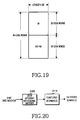
- FIG. 19 illustrates a structure of the extended orthogonal code.
- M1 is the mask function in use
- 32 orthogonal codewords W of length 32 are used for the upper 32 codewords
- the mask function for optimizing a (24,6) code is determined experimentally .
- the mask function M1 is as follows.
- the (24,6) codeword is generated by puncturing 8 symbols from the 32 coded symbols output from a (32,6) extended code generator.
- a change in the puncturing positions where the 8 symbols are punctured from the 32 extended coded symbols causes a change in the minimum distance d min of the codeword. Therefore, in order to make a (24,6) encoder with excellent error correcting performance in the (32,6) extended orthogonal code, it is important to calculate the puncturing positions where the largest minimum distance can be obtained.
- the 8 puncturing positions needed for generating an optimal (24,6) linear code are calculated through experimentation.
- the simplest puncturing pattern is ⁇ 0,1,2,3,4,5,6,7 ⁇ .
- a transmitter and a receiver of the mobile communication system transmitting the 6 information bits using the encoding/decoding method according to the present invention previously exchange or otherwise pre-store the 8 puncturing positions.
- the puncturing positions are generally defined in a communication protocol. Alternatively, the transmitter may previously provide information on the puncturing positions.
- FIG. 20 illustrates a structure of an optimal (24,6) encoder included in the transmitter according to an embodiment of the present invention.
- 6 input information bits a0, a1, a2, a3, a4 and a5 are applied to a (32,6) extended orthogonal encoder 2100.
- the 6 input information bits a0 a1, a2, a3, a4 and a5 constitute a rate indicator.
- the extended orthogonal encoder 2100 encodes the 6 input information bits a0, a1, a2, a3, a4 and a5, and outputs coded symbols of length 32 (or a coded symbol stream).
- the 32 coded symbols output from the extended orthogonal encoder 2100 are provided to a puncturer 2110.
- the puncturer 2110 punctures 0 th , 1 st , 2 nd , 3 rd , 4 th , 5 th , 6 th and 7 th symbols in the 8 optimal puncturing positions from the 32 coded symbols, and outputs 24 coded symbols.
- a general code theory defines a generating matrix to show a mapping relation between the input information and the coded symbols.
- a generating matrix for a final (24,6) encoder is represented by
- the generating matrix of Equation 6 selects 24 symbols in a first row if the first input information bit among the 6 input information bits is 1, and selects no symbol if the first input information bit is 0.
- the generating matrix selects 24 symbols in a second row if the second input information bit among the 6 input information bits is 1, and selects no symbol if the second input information bit is 0.
- the generating matrix selects 24 symbols in a third row if the third input information bit among the 6 input information bits is 1, and selects no symbol if the third input information bit is 0.
- the generating matrix selects 24 symbols in a fourth row if the fourth input information bit among the 6 input information bits is 1, and selects no symbol if the fourth input information bit is 0.
- the generating matrix selects 24 symbols in a fifth row if the fifth input information bit among the 6 input information bits is 1, and selects no symbol if the fifth input information bit is 0. Finally, the generating matrix selects 24 symbols in a sixth row if the sixth input information bit among the 6 input information bits is 1, and selects no symbol if the sixth input information bit is 0.
- a coded symbol stream for the input information bits is generated by XORing all the selected streams in a symbol unit.
- FIG. 21 illustrates a (24,6) encoder based on the above generating matrix.
- an input information bit a0 is applied to a multiplier 2220
- an input information bit a1 is applied to a multiplier 2222
- an input information bit a2 is applied to a multiplier 2224
- an input information bit a3 is applied to a multiplier 2226
- an input information bit a4 is applied to a multiplier 2228
- an input information bit a5 is applied to a multiplier 2230, respectively.
- a signal generator 2200 provides 6 symbol streams R1-R6 constituting the generating matrix, stored in a memory, to the multipliers 2220-2230, respectively.
- the multiplier 2224 multiplies the symbols of the received symbol stream R3 by the input information bit a2, and outputs a symbol stream of length 24 to the XOR operator 2240.
- the multiplier 2226 multiplies the symbols of the received symbol stream R4 by the input information bit a3, and outputs a symbol stream of length 24 to the XOR operator 2240.
- the multiplier 2228 multiplies the symbols of the received symbol stream R5 by the input information bit a4, and outputs a symbol stream of length 24 to the XOR operator 2240.
- the multiplier 2230 multiplies the symbols of the received symbol stream R6 by the input information bit a5, and outputs a symbol stream of length 24 to the XOR operator 2240.
- the XOR operator 2240 then XORs the 6 symbol streams of length 24 in a symbol unit, and outputs a coded symbol stream of length 24.
- the (24,7) encoder provided by the invention is constructed to generate an optimal (24,7) code by puncturing 8 symbols from an extended orthogonal code obtained by extending a codeword using 2 mask functions for a (32,5) orthogonal code (or first order Reed-Muller code).
- FIG. 3 illustrates a structure of the extended orthogonal code.
- the 2 mask functions for optimizing a (24,7) code are determined experimentally.
- the 2 mask functions M1 and M2 are as follows.
- the (24,7) codeword is generated by puncturing 8 symbols from the 32 coded symbols output from a (32,7) extended code generator.
- a change in the puncturing positions where the 8 symbols are punctured from the 32 extended coded symbols causes a change in the minimum distance d min of the codeword. Therefore, in order to make a (24,7) encoder with excellent error correcting performance in the (32,7) extended orthogonal code, it is important to calculate the puncturing positions where the largest minimum distance can be obtained.
- the 8 puncturing positions needed for generating an optimal (24,7) linear code can be calculated through experimentation.
- the simplest puncturing pattern is ⁇ 0,4,8,12,16,20,24,28 ⁇ or ⁇ 0, 1, 2, 3, 4, 5, 6, 7 ⁇ .
- a transmitter and a receiver of the mobile communication system transmitting the 7 information bits using the encoding/decoding method according to the present invention previously exchange or otherwise pre-store the 8 puncturing positions.
- the puncturing positions are generally defined in a communication protocol. Alternatively, the transmitter may previously provide information on the puncturing positions.
- FIG. 4 illustrates a structure of an optimal (24,7) encoder included in the transmitter according to an embodiment of the present invention.
- 7 input information bits a0, a1, a2, a3, a4, a5 and a6 are applied to a (32,7) extended orthogonal encoder 400.
- the 7 input information bits a0, a1, a2, a3, a4, a5 and a6 constitute a rate indicator.
- the extended orthogonal encoder 400 encodes the 7 input information bits a0, a1, a2, a3, a4, a5 and a6, and outputs coded symbols (or a coded symbol stream) of length 32.
- the 32 coded symbols output from the extended orthogonal encoder 400 are provided to a puncturer 410.
- the puncturer 410 punctures 0 th , 4 th , 8 th , 12 th , 16 th , 20 th , 24 th and 28 th symbols or 0 th , 1 st , 2 nd , 3 rd , 4 th , 5 th , 6 th and 7 th symbols in the 8 optimal puncturing positions from the 32 coded symbols, and outputs 24 coded symbols.
- a general code theory defines a generating matrix to show a mapping relation between the input information and the coded symbols.
- a generating matrix for a final (24,7) encoder is represented by
- the generating matrix of Equation 7 selects 24 symbols in a first row if the first input information bit among the 7 input information bits is 1, and selects no symbol if the first input information bit is 0.
- the generating matrix selects 24 symbols in a second row if the second input information bit among the 7 input information bits is 1, and selects no symbol if the second input information bit is 0.
- the generating matrix selects 24 symbols in a third row if the third input information bit among the 7 input information bits is 1, and selects no symbol if the third input information bit is 0.
- the generating matrix selects 24 symbols in a fourth row if the fourth input information bit among the 7 input information bits is 1, and selects no symbol if the fourth input information bit is 0.
- the generating matrix selects 24 symbols in a fifth row if the fifth input information bit among the 7 input information bits is 1, and selects no symbol if the fifth input information bit is 0.
- the generating matrix selects 24 symbols in a sixth row if the sixth input information bit among the 7 input information bits is 1, and selects no symbol if the sixth input information bit is 0.
- the generating matrix selects 24 symbols in a seventh row if the seventh input information bit among the 7 input information bits is 1, and selects no symbol if the seventh input information bit is 0.
- a coded symbol stream for the input information bits is generated by XORing all of the selected rows in a symbol unit.
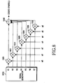
- FIG. 8 illustrates a (24,7) encoder based on the above generating matrix.
- an input information bit a0 is applied to a multiplier 1020
- an input information bit a1 is applied to a multiplier 1022
- an input information bit a2 is applied to a multiplier 1024
- an input information bit a3 is applied to a multiplier 1026
- an input information bit a4 is applied to a multiplier 1028
- an input information bit a5 is applied to a multiplier 1030
- an input information bit a6 is applied to a multiplier 1032, respectively.
- a signal generator 1000 provides 7 symbol streams R1-R7 constituting the generating matrix, stored in a memory, to the multipliers 1020-1032, respectively.
- the multiplier 1022 multiplies the symbols of the symbol stream R2 by the input information bit a1, and outputs a symbol stream of length 24 to the XOR operator 1040.
- the multiplier 1024 multiplies the symbols of the symbol stream R3 by the input information bit a2, and outputs a symbol stream of length 24 to the XOR operator 1040.
- the multiplier 1026 multiplies the symbols of the symbol stream R4 by the input information bit a3, and outputs a symbol stream of length 24 to the XOR operator 1040.
- the multiplier 1028 multiplies the symbols of the symbol stream R5 by the input information bit a4, and outputs a symbol stream of length 24 to the XOR operator 1040.
- the multiplier 1030 multiplies the symbols of the symbol stream R6 by the input information bit a5, and outputs a symbol stream of length 24 to the XOR operator 1040.
- the multiplier 1032 multiplies the symbols of the symbol stream R7 by the input information bit a6, and outputs a symbol stream of length 24 to the XOR operator 1040.
- the XOR operator 1040 then XORs the 7 symbol streams of length 24 in a symbol unit, and outputs a coded symbol stream of length 24.
- the above (24,1) encoder, (24,2) encoder, (24,3) encoder, (24,4) encoder, (24,5) encoder, (24,6) encoder and (24,7) encoder have something in common with one another in that they can be analogized from the structure of the orthogonal code in the light of the structure of the encoder. That is, the (24,1) encoder uses the (2,1) orthogonal code, the (24,2) encoder uses the (4,2) orthogonal code, the (24,3) encoder uses the (8,3) orthogonal code, the (24,4) encoder uses the (16,4) orthogonal code, and the (24,5) encoder uses the (32,5) orthogonal code.
- the (32,6) extended orthogonal code used in the (24,6) encoder is an orthogonal code extended by the (32,5) encoder using a basis (mask function) of one additional codeword.
- the (32,7) extended orthogonal code used in the (24,7) encoder is an orthogonal code extended by the (32,5) encoder using bases (mask functions) of two additional codewords. Therefore, the (24,1) encoder, (24,2) encoder, (24,3) encoder, (24,4) encoder, (24,5) encoder, (24,6) encoder and (24,7) encoder have the above-stated common point.
- a first embodiment of the present invention provides a single encoder capable of serving as all of the (24,1) encoder, (24,2) encoder, (24,3) encoder, (24,4) encoder, (24,5) encoder, (24,6) encoder and (24,7) encoder having different sizes.
- FIG. 5 illustrates a structure of an encoder serving as all of the (24,1) encoder, (24,2) encoder, (24,3) encoder, (24,4) encoder, (24,5) encoder, (24,6) encoder and (24,7) encoder having different lengths. That is, the encoder of FIG. 5 encodes 1 to 7 input information bits with different Walsh codes or masks having a length of 2, 4, 8, 16 or 32, and outputs a coded symbol stream having 24 coded symbols.
- a controller 510 controls an encoding operation by determining the number of the input information bits. That is, when the number of the input information bits is 1, the controller 510 controls a Walsh code generator 500 to generate one Walsh code having a length of 2. Further, the controller 510 sets a repetition frequency of a repeater 550 to 32, and controls a puncturer 560 to puncture symbols in the 40 puncturing positions corresponding to the one input information bit. When the number of the input information bits is 2, the controller 510 controls the Walsh code generator 500 to generate 2 different Walsh codes having a length of 4. Further, the controller 510 sets a repetition frequency of the repeater 550 to 8, and controls the puncturer 560 to puncture symbols in the 8 puncturing positions corresponding to the 2 input information bits.
- the controller 510 controls the Walsh code generator 500 to generate 3 different Walsh codes having a length of 8. Further, the controller 510 sets a repetition frequency of the repeater 550 to 4, and controls the puncturer 560 to puncture symbols in the 8 puncturing positions corresponding to the 3 input information bits. When the number of the input information bits is 4, the controller 510 controls the Walsh code generator 500 to generate 4 different Walsh codes having a length of 16. Further, the controller 510 sets a repetition frequency of the repeater 550 to 2, and controls the puncturer 560 to puncture symbols in the 8 puncturing positions corresponding to the 4 input information bits. When the number of the input information bits is 5, the controller 510 controls the Walsh code generator 500 to generate 5 different Walsh codes having a length of 32.
- the controller 510 sets a repetition frequency of the repeater 550 to 1, and controls the puncturer 560 to puncture symbols in the 8 puncturing positions corresponding to the 5 input information bits.
- the controller 510 controls the Walsh code generator 500 and a mask generator 505 to generate 5 different Walsh codes and one mask, all having a length of 32, respectively.
- the controller 510 sets a repetition frequency of the repeater 550 to 1, and controls the puncturer 560 to puncture symbols in the 8 puncturing positions corresponding to the 6 input information bits.
- the controller 510 controls the Walsh code generator 500 and the mask generator 505 to generate 5 different Walsh codes and 2 different masks, all having a length of 32, respectively.
- the controller 510 sets a repetition frequency of the repeater 550 to 1, and controls the puncturer 560 to puncture symbols in the 8 puncturing positions corresponding to the 7 input information bits.
- the Walsh code generator 500 under the control of the controller 510, selectively generates different Walsh codes of length 2, 4, 8, 16 or 32. For example, upon receiving one input information bit, the Walsh code generator 500 generates one Walsh code of length 2 under the control of the controller 510. Upon receiving 2 input information bits, the Walsh code generator 500 generates 2 different Walsh codes of length 4 under the control of the controller 510. Upon receiving 3 input information bits, the Walsh code generator 500 generates 3 different Walsh codes of length 8 under the control of the controller 510. Upon receiving 4 input information bits, the Walsh code generator 500 generates 4 different Walsh codes of length 16 under the control of the controller 510. Upon receiving 5 to 7 input information bits, the Walsh code generator 500 generates 5 different Walsh codes of length 32 under the control of the controller 510.
- the mask generator 505 selectively generates masks of length 32 under the control of the controller 510. For example, upon receiving 1 to 5 input information bits, the mask generator 505 generates no mask under the control of the controller 510. However, upon receiving 6 input information bits, the mask generator 505 generates one mask of length 32 under the control of the controller 510. Further, upon receiving 7 input information bits, the mask generator 505 generates two different masks of length 32 under the control of the controller 510. Alternatively, the mask generator 505 may be designed to continuously generate 2 different masks, without being controlled by the controller 510. In this case, 0's are input as the input information bits in order not to affect the output of the XOR operator 540.
- Multipliers 520-532 multiply the 1 to 7 input information bits by the Walsh codes and the masks from the Walsh code generator 500 and the mask generator 505 on a one-to-one basis, and output coded symbol streams each having 2, 4, 8, 16 or 32 coded symbols.
- coded symbol streams each having 2, 4, 8, 16 or 32 coded symbols.
- the repeater 550 repeats the coded symbol stream from the XOR operator 540 a predetermined number of times, and outputs a coded symbol stream having 64 coded symbols. For example, when one input bit is received as the input information bit, the repeater 550 repeats 32 times the 2 coded symbols output from the XOR operator 540 under the control of the controller 510, and outputs a coded symbol stream having 64 coded symbols. However, when 2 to 7 input bits are received as the input information bits, the repeater 550 repeats 8, 4, 2 or 1 times the 4, 8, 16 or 32 coded symbols output from the XOR operator 540 under the control of the controller 510, and outputs a coded symbol stream having 32 coded symbols.
- a memory 570 stores 8 puncturing positions corresponding to each of the 1 to 7 input information bits.
- the 40 puncturing positions corresponding to the 1 input information bit, stored in the memory 570 are all the even-numbered symbol positions and 1 st , 3 rd , 5 th , 7 th , 9 th , 11 th , 13 th and 15 th symbol positions.
- the 8 puncturing positions corresponding to the 2 input information bit, stored in the memory 570 are 0 th , 4 th , 8 th , 12 th , 16 th , 20 th , 24 th and 28 th symbol positions.
- the 8 puncturing positions corresponding to the 3 input information bit, stored in the memory 570 are 0 th , 3 rd , 5 th , 6 th , 7 th , 8 th , 16 th and 24 th symbol positions.
- the 8 puncturing positions corresponding to the 4 input information bits, stored in the memory 570 are 0 th , 1 st , 2 nd , 3 rd , 4 th , 5 th , 6 th and 16 th symbol positions.
- the 8 puncturing positions corresponding to the 5 input information bits, stored in the memory 570 are 0 th , 1 st , 2 nd , 3 rd , 4 th , 5 th , 6 th and 7 th symbol positions.
- the 8 puncturing positions corresponding to the 6 input information bits, stored in the memory 570 are 0 th , 1 st , 2 nd , 3 rd , 4 th , 5 th , 6 th and 7 th symbol positions.
- the 8 puncturing positions corresponding to the 7 input information bits, stored in the memory 570, are 0 th , 1 st , 2 nd , 3 rd , 4 th , 5 th , 6 th and 7 th symbol positions.
- the puncturer 560 receives the coded symbol stream having 32 or 64 coded symbols from the repeater 550, punctures coded symbols in the 8 or 40 puncturing positions read from the memory 570 from the 32 or 64 coded symbols under the control of the controller 510, and outputs a coded symbol stream having 24 coded symbols. That is, if the number of the input information bits is 1, the puncturer 560 punctures the coded symbols in the 40 puncturing positions read from the memory 570 among the 64 coded symbols output from the repeater 550 under the control of the controller 510, and outputs a coded symbol stream having 24 coded symbols.
- the puncturer 560 punctures the coded symbols in the 8 puncturing positionsread from the memory 570 among the 32 coded symbols output from the repeater 550 under the control of the controller 510, and outputs a coded symbol stream having 24 coded symbols. Specifically, if the number of the input information bits is 1, the puncturer 560 punctures all the even-numbered coded symbols and the 1 st , 3 rd , 5 th , 7 th , 9 th , 11 th , 13 th and 15 th coded symbols (as shown in Table 1) from the 64 coded symbols output from the repeater 550, and outputs a coded symbol stream having 24 coded symbols.
- the puncturer 560 punctures the 0 th , 4 th , 8 th , 12 th , 16 th , 20 th , 24 th and 28 th coded symbols from the 32 coded symbols output from the repeater 550, and outputs a coded symbol stream having 24 coded symbols. If the number of the input information bits is 3, the puncturer 560 punctures the 0 th , 3 rd , 5 th , 6 th , 7 th , 8 th , 16 th and 24 th coded symbols from the 32 coded symbols output from the repeater 550, and outputs a coded symbol stream having 24 coded symbols.
- the puncturer 560 punctures the 0 th , 1 st , 2 nd , 3 rd , 4 th , 5 th , 6 th and 16 th coded symbols from the 32 coded symbols output from the repeater 550, and outputs a coded symbol stream having 24 coded symbols.
- the puncturer 560 punctures the 0 th , 4 th , 8 th , 12 th , 16 th , 20 th , 24 th and 28 th coded symbols or the 0 th , 1 st , 2 nd , 3 rd , 4 th , 5 th , 6 th and 7 th coded symbols from the 32 coded symbols output from the repeater 550, and outputs a coded symbol stream having 24 coded symbols.
- the puncturer 560 punctures the 0 th , 4 th , 8 th , 12 th , 16 th , 20 th , 24 th and 28 th coded symbols or the 0 th , 1 st , 2 nd , 3 rd , 4 th , 5 th , 6 th and 7 th coded symbols from the 32 coded symbols output from the repeater 550, and outputs a coded symbol stream having 24 coded symbols.
- the puncturer 560 punctures the 0 th , 4 th , 8 th , 12 th , 16 th , 20 th , 24 th and 28 th coded symbols or the 0 th , 1 st , 2 nd , 3 rd , 4 th , 5 th , 6 th and 7 th coded symbols from the 32 coded symbols output from the repeater 550, and outputs a coded symbol stream having 24 coded symbols.
- the encoder serves as a (24,1) encoder to a (24,7) encoder. It will be assumed herein that the input information bits applied to the encoder constitute a rate indicator.
- the encoder serves as the (24,7) encoder.
- a 7-bit rate indicator of a0, a1, a2, a3, a4, a5 and a6 is applied to the encoder, and at the same time, bit information indicating that the 7-bit rate indicator is applied to the encoder is provided to the controller 510.
- the controller 510 then provides the Walsh code generator 500 with a control signal instructing it to generate Walsh codes of length 32.
- the Walsh code generator 500 Upon receiving the control signal, the Walsh code generator 500 generates Walsh codes W1, W2, W4, W8 and W16 of length 32, and provides the generated Walsh codes W1, W2, W4, W8 and W16 to the associated multipliers, respectively.
- the Walsh code W1 is provided to the multiplier 520, the Walsh code W2 to the multiplier 522, the Walsh code W4 to the multiplier 524, the Walsh code W8 to the multiplier 526, and the Walsh code W16 to the multiplier 528.
- Shown in Table 2 are the Walsh codes of length 32 generated by the Walsh code generator 500.
- Table 4 shows the input information bits and the Walsh codes or masks provided to the respective multipliers.
- the multipliers multiply the input information bits by the Walsh codes or masks, provided thereto as shown in Table 4, and provide their outputs to the XOR operator 540.
- the multiplier 520 multiplies the input information bit a0 by the Walsh code W1 every symbol (i.e., in a symbol unit), and provides its output to the XOR operator 540.
- the multiplier 522 multiplies the input information bit a1 by the Walsh code W2 every symbol, and provides its output to the XOR operator 540.
- the multiplier 524 multiplies the input information bit a2 by the Walsh code W4 every symbol, and provides its output to the XOR operator 540.
- the multiplier 526 multiplies the input information bit a3 by the Walsh code W8 every symbol, and provides its output to the XOR operator 540.
- the multiplier 528 multiplies the input information bit a4 by the Walsh code W16 every symbol, and provides its output to the XOR operator 540.
- the multiplier 530 multiplies the input information bit a5 by the mask M1 every symbol, and provides its output to the XOR operator 540.
- the multiplier 532 multiplies the input information bit a6 by the mask M2 every symbol, and provides its output to the XOR operator 540.
- the XOR operator 540 then XORs the symbol streams of length 32 output from the multipliers 520, 522, 524, 526, 528, 530 and 532 in a symbol unit, and provides its output to the repeater 550.
- the controller 510 provides the repeater 550 with a control signal for controlling a repetition frequency over the output of the XOR operator 540.
- the repeater 550 does not perform repetition (herein, defined as one-time repetition).
- the controller 510 provides the repeater 550 with a control signal instructing it to output the intact input signal.
- the repeater 550 provides the puncturer 560 with the intact symbol stream of length 32 output from the XOR operator 540.
- the controller 510 provides the puncturer 560 with a control signal instructing it to puncture symbols in the puncturing positions for the (24,7) code.
- the controller 510 may provide the puncturer 560 with length information (7 bits) of the rate indicator as the control signal.
- the puncturer 560 then receives 8 puncturing positions corresponding to the 7 input information bits of the rate indicator from the memory 570, and punctures coded symbols in the 8 puncturing positions from the coded symbols of length 32 provided from the repeater 550. That is, the puncturer 560 punctures 8 symbols in the puncturing positions read from the memory 570 among the coded symbols of length 32 provided from the repeater 550.
- the puncturer 560 punctures 0 th , 4 th , 8 th , 12 th , 16 th , 20 th , 24 th and 28 th coded symbols from the coded symbols of length 32, and outputs 24 coded symbols.
- the encoder may puncture the 0 th , 1 st , 2 nd , 3 rd , 4 th , 5 th , 6 th and 7 th coded symbols from the coded symbol stream of length 32 in order to reduce hardware complexity.
- the encoder serves as the (24,6) encoder.
- a 6-bit rate indicator of a0, a1, a2, a3, a4 and a5 is applied to the encoder, and the remaining rate indicator bit a6 is initialized to 0 and applied to the encoder.
- bit information indicating that the 6-bit rate indicator is applied to the encoder is provided to the controller 510.
- the controller 510 then provides the Walsh code generator 500 with a control signal instructing it to generate Walsh codes of length 32.
- the Walsh code generator 500 Upon receiving the control signal, the Walsh code generator 500 generates Walsh codes W1, W2, W4, W8 and W16 of length 32, and provides the generated Walsh codes W1, W2, W4, W8 and W16 to the associated multipliers, respectively.
- the Walsh code W1 is provided to the multiplier 520, the Walsh code W2 to the multiplier 522, the Walsh code W4 to the multiplier 524, the Walsh code W8 to the multiplier 526, and the Walsh code W16 to the multiplier 528. Shown in Table 5 are the Walsh codes of length 32 generated by the Walsh code generator 500.
- Table 7 are the input information bits and the Walsh codes or mask provided to the respective multipliers.
- the multipliers multiply the input information bits by the Walsh codes or mask, provided thereto as shown in Table 7, and provide their outputs to the XOR operator 540.
- the multiplier 520 multiplies the input information bit a0 by the Walsh code W1 every symbol (i.e., in a symbol unit), and provides its output to the XOR operator 540.
- the multiplier 522 multiplies the input information bit a1 by the Walsh code W2 every symbol, and provides its output to the XOR operator 540.
- the multiplier 524 multiplies the input information bit a2 by the Walsh code W4 every symbol, and provides its output to the XOR operator 540.
- the multiplier 526 multiplies the input information bit a3 by the Walsh code W8 every symbol, and provides its output to the XOR operator 540.
- the multiplier 528 multiplies the input information bit a4 by the Walsh code W16 every symbol, and provides its output to the XOR operator 540.
- the multiplier 530 multiplies the input information bit a5 by the mask M1 every symbol, and provides its output to the XOR operator 540.
- an output of the multiplier 532 does not affect the output of the XOR operator 540 regardless of the mask M2 from the mask generator 505. That is, the multiplier 532 outputs a symbol stream comprised of coded symbols all having a value '0' regardless of symbol values of the symbol stream from the mask generator 505. Therefore, the output of the multiplier 532 does not affect the output of the XOR operator 540.
- Initializing the input information bit a6 to 0 is equivalent to a switching operation for cutting off the output of the multiplier 532.
- the XOR operator 540 then XORs the symbol streams of length 32 output from the multipliers 520, 522, 524, 526, 528, 530 and 532 in a symbol unit, and provides its output to the repeater 550.
- the controller 510 provides the repeater 550 with a control signal for controlling a repetition frequency over the output of the XOR operator 540.
- the repeater 550 has a repetition frequency of 1. Therefore, the controller 510 provides die repeater 550 with a control signal instructing it to repeat the input signal once (i.e., to output the intact input signal).
- the repeater 550 provides the puncturer 560 with the intact symbol stream of length 32 output from the XOR operator 540.
- the controller 510 provides the puncturer 560 with a control signal instructing it to puncture symbols in the puncturing positions for the (24,6) code.
- the controller 510 provides the puncturer 560 with length information (6 bits) of the rate indicator as the control signal.
- the puncturer 560 then receives 8 puncturing positions corresponding to the 6 input information bits of the rate indicator from the memory 570, and punctures coded symbols in the 8 puncturing positions from the coded symbols of length 32 provided from the repeater 550. That is, the puncturer 560 punctures 8 symbols in the puncturing positions read from the memory 570 among the coded symbols of length 32 provided from the repeater 550.
- the puncturer 560 punctures 0 th , 4 th , 8 th , 12 th , 16 th , 20 th , 24 th and 28 th coded symbols from the coded symbols of length 32, and outputs 24 coded symbols.
- the encoder may puncture the 0 th , 1 st , 2 nd , 3 rd , 4 th , 5 th , 6 th and 7 th coded symbols from the coded symbol stream of length 32 in order to reduce hardware complexity.
- the encoder serves as the (24,5) encoder.
- a 5-bit rate indicator of a0, a1, a2, a3 and a4 is applied to the encoder, and the remaining rate indicator bits a5 and a6 are initialized to 0 and applied to the encoder.
- bit information indicating that the 5-bit rate indicator is applied to the encoder is provided to the controller 510.
- the controller 510 then provides the Walsh code generator 500 with a control signal instructing it to generate Walsh codes of length 32.
- the Walsh code generator 500 Upon receiving the control signal, the Walsh code generator 500 generates Walsh codes W1, W2, W4, W8 and W16 of length 32, and provides the generated Walsh codes W1, W2, W4, W8 and W16 to the associated multipliers, respectively.
- the Walsh code W1 is provided to the multiplier 520, the Walsh code W2 to the multiplier 522, the Walsh code W4 to the multiplier 524, the Walsh code W8 to the multiplier 526, and the Walsh code W16 to the multiplier 528.
- Shown in Table 8 are the Walsh codes of length 32 generated by the Walsh code generator 500.
- Table 10 are the input information bits and the Walsh codes provided to the respective multipliers.
- the multipliers multiply the input information bits by the Walsh codes, provided thereto as shown in Table 10, and provide their outputs to the XOR operator 540.
- the multiplier 520 multiplies the input information bit a0 by the Walsh code W1 every symbol (i.e., in a symbol unit), and provides its output to the XOR operator 540.
- the multiplier 522 multiplies the input information bit a1 by the Walsh code W2 every symbol, and provides its output to the XOR operator 540.
- the multiplier 524 multiplies the input information bit a2 by the Walsh code W4 every symbol, and provides its output to the XOR operator 540.
- the multiplier 526 multiplies the input information bit a3 by the Walsh code W8 every symbol, and provides its output to the XOR operator 540.
- the multiplier 528 multiplies the input information bit a4 by the Walsh code W16 every symbol, and provides its output to the XOR operator 540.
- the XOR operator 540 then XORs the symbol streams of length 32 output from the multipliers 520, 522, 524, 526, 528, 530 and 532 in a symbol unit, and provides its output to the repeater 550.
- the controller 510 provides the repeater 550 with a control signal for controlling a repetition frequency over the output of the XOR operator 540.
- the repeater 550 has a repetition frequency of 1. Therefore, the controller 510 provides the repeater 550 with a control signal instructing it to repeat the input signal once (i.e., to output the intact input signal).
- the repeater 550 provides the puncturer 560 with the intact symbol stream of length 32 output from the XOR operator 540.
- the controller 510 provides the puncturer 560 with a control signal instructing it to puncture symbols in the puncturing positions for the (24,5) code.
- the puncturer 560 then receives 8 puncturing positions read from the memory 570, and punctures coded symbols in the 8 puncturing positions from the coded symbols of length 32 provided from the repeater 550. That is, the puncturer 560 punctures 8 symbols in the puncturing positions read from the memory 570 among the coded symbols of length 32 provided from the repeater 550.
- the punctures 560 punctures 0 th , 4 th , 8 th , 12 th , 16 th , 20 th , 24 th and 28 th coded symbols from the coded symbols of length 32, and outputs 24 coded symbols.
- the encoder may puncture the 0 th , 1 st , 2 nd , 3 rd , 4 th , 5 th , 6 th and 7 th coded symbols from the coded symbol stream of length 32 in order to reduce hardware complexity.
- the encoder serves as the (24,4) encoder.
- a 4-bit rate indicator of a0, a1, a2 and a3 is applied to the encoder, and the remaining input information bits a4, a5 and a6 are initialized to '0'.
- bit information indicating that the 4-bit rate indicator is applied to the encoder is provided to the controller 510.
- the controller 510 then provides the Walsh code generator 500 with a control signal instructing it to generate Walsh codes of length 16.
- the Walsh code generator 500 Upon receiving the control signal, the Walsh code generator 500 generates Walsh codes W1, W2, W4 and W8 of length 16, and provides the generated Walsh codes W1, W2, W4 and W8 to the associated multipliers, respectively.
- the Walsh code W1 is provided to the multiplier 520, the Walsh code W2 to the multiplier 522, the Walsh code W4 to the multiplier 524, and the Walsh code W8 to the multiplier 526. Shown in Table 11 are the Walsh codes of length 16 generated by the Walsh code generator 500.
- Table 13 are the input information bits and the Walsh codes provided to the respective multipliers.
- the multipliers multiply the input information bits by the Walsh codes, provided thereto as shown in Table 13, and provide their outputs to the XOR operator 540.
- the multiplier 520 multiplies the input information bit a0 by the Walsh code W1 every symbol, and provides its output to the XOR operator 540.
- the multiplier 522 multiplies the input information bit a1 by the Walsh code W2 every symbol, and provides its output to the XOR operator 540.
- the multiplier 524 multiplies the input information bit a2 by the Walsh code W4 every symbol, and provides its output to the XOR operator 540.
- the multiplier 526 multiplies the input information bit a3 by the Walsh code W8 every symbol, and provides its output to the XOR operator 540.
- the multipliers 528, 530 and 532 receive the input information bits a4, a5 and a6 initialized to '0', the outputs of the multipliers 528, 530 and 532 do not affect the output of the XOR operator 540 regardless of the Walsh code W16 from the Walsh code generator 500 and the masks M1 and M2 from the mask generator 505.
- the multiplier 528 outputs a symbol stream having coded symbols all having a value '0' regardless of a value of the Walsh code W16 from the Walsh code generator 500.
- the multipliers 530 and 532 output symbol streams each having coded symbols all having a value '0' regardless of values of the masks M1 and M2 from the mask generator 505.
- the XOR operator 540 then XORs the symbol streams of length 16 output from the multipliers 520, 522, 524, 526, 528, 530 and 532 in a symbol unit, and provides its output to the repeater 550.
- the controller 510 provides the repeater 550 with a control signal for controlling a repetition frequency over the output of the XOR operator 540.
- the controller 510 provides the repeater 550 with a control signal instructing it to repeat the input signal two times.
- the repeater 550 repeats the symbol stream of length 16 output from the XOR operator 540 two times, and provides the puncturer 560 with a symbol stream of length 32.
- the controller 510 provides the puncturer 560 with a control signal instructing it to puncture symbols in the puncturing positions for the (24,4) code.
- the puncturer 560 then receives 8 puncturing positions read from the memory 570, and punctures coded symbols in the 8 puncturing positions from the coded symbols of length 32 provided from the repeater 550. That is, the puncturer 560 punctures 8 symbols in the puncturing positions read from the memory 570 among the coded symbols of length 32 provided from the repeater 550.
- the puncturer 560 punctures 0 th , 1 st , 2 nd , 3 rd , 4 th , 5 th , 6 th and 16 th coded symbols from the coded symbols of length 32, and outputs 24 coded symbols.
- the encoder serves as the (24,3) encoder.
- a 3-bit rate indicator of a0, a1 and a2 is applied to the encoder, and the remaining input information bits a3, a4, a5 and a6 applied to the encoder are initialized to '0'.
- bit information indicating that the 3-bit rate indicator is applied to the encoder is provided to the controller 510.
- the controller 510 then provides the Walsh code generator 500 with a control signal instructing it to generate Walsh codes of length 8.
- the Walsh code generator 500 Upon receiving the control signal, the Walsh code generator 500 generates Walsh codes W1, W2 and W4 of length 8, and provides the generated Walsh codes W1, W2 and W4 to the associated multipliers, respectively.
- the Walsh code W1 is provided to the multiplier 520, the Walsh code W2 to the multiplier 522, and the Walsh code W4 to the multiplier 524. Shown in Table 14 are the Walsh codes of length 8 generated by the Walsh code generator 500.
- Table 16 are the input information bits and the Walsh codes provided to the respective multipliers.
- the multipliers multiply the input information bits by the Walsh codes, provided thereto as shown in Table 16, and provide their outputs to the XOR operator 540.
- the multiplier 520 multiplies the input information bit a0 by the Walsh code W1 every symbol, and provides its output to the XOR operator 540.
- the multiplier 522 multiplies the input information bit a1 by the Walsh code W2 every symbol, and provides its output to the XOR operator 540.
- the multiplier 524 multiplies the input information bit a2 by the Walsh code W4 every symbol, and provides its output to the XOR operator 540.
- the multipliers 526, 528, 530 and 532 receive the input infonnation bits a3, a4, a5 and a6 initialized to 0, the outputs of the multipliers 526, 528, 530 and 532 do not affect the output of the XOR operator 540 regardless of the Walsh codes W8 and W16 from the Walsh code generator 500 and the masks M1 and M2 from the mask generator 505.
- the multipliers 526 and 528 output symbol streams each comprised of coded symbols all having a value '0' regardless of symbol values of the Walsh codes W8 and W16 from the Walsh code generator 500.
- the multipliers 530 and 532 output symbol streams each comprised of coded symbols all having a value '0' regardless of symbol values of the masks M1 and M2 from the mask generator 505.
- the outputs of the multipliers 526, 528, 530 and 532 do not affect the output of the XOR operator 540, though they are provided to the XOR operator 540.
- Initializing the input information bits a3, a4, a5 and a6 to '0' is equivalent to a switching operation for cutting off the outputs of the multipliers 526, 528, 530 and 532.
- the XOR operator 540 then XORs the symbol streams of length 8 output from the multipliers 520, 522, 524, 526, 528, 530 and 532 in a symbol unit, and provides its output to the repeater 550.
- the controller 510 provides the repeater 550 with a control signal for controlling a repetition frequency over the output of the XOR operator 540.
- the controller 510 provides the repeater 550 with a control signal instructing it to repeat the input signal four times.
- the repeater 550 repeats the symbol stream of length 8 output from the XOR operator 540 four times, and provides the puncturer 560 with a symbol stream of length 32.
- the controller 510 provides the puncturer 560 with a control signal instructing it to puncture symbols in the puncturing positions for the (24,3) code.
- the controller 510 may provide the puncturer 560 with length information (3 bits) of the rate indicator as the control signal.
- the puncturer 560 then receives 8 puncturing positions corresponding to the 3 input information bits of the rate indicator from the memory 570, and punctures coded symbols in the 8 puncturing positions from the coded symbols of length 32 provided from the repeater 550. That is, the puncturer 560 punctures 8 symbols in the puncturing positions read from the memory 570 among the coded symbols of length 32 provided from the repeater 550.
- the punctures 560 punctures 0 th , 3 rd , 5 th , 6 th , 7 th , 8 th , 16 th and 24 th coded symbols from the coded symbols of length 32, and outputs 24 coded symbols.
- the encoder serves as the (24,2) encoder.
- a 2-bit rate indicator of a0 and a1 is applied to the encoder, and the remaining input information bits a2, a3, a4, a5 and a6 applied to the encoder are initialized to '0'.
- bit information indicating that the 2-bit rate indicator is applied to the encoder is provided to the controller 510.
- the controller 510 then provides the Walsh code generator 500 with a control signal instructing it to generate Walsh codes of length 4.
- the Walsh code generator 500 Upon receiving the control signal, the Walsh code generator 500 generates Walsh codes W1 and W2 of length 4, and provides the generated Walsh codes W1 and W2 to the associated multipliers, respectively.
- the Walsh code W1 is provided to the multiplier 520 and the Walsh code W2 to the multiplier 522. Shown in Table 17 are the Walsh codes of length 4 generated by the Walsh code generator 500.
- Multiplier Walsh Code Input Information Bit Multiplier 520 W1 0101 a0
- Multiplier 522 W2 0011 a1
- the multipliers multiply the input information bits by the Walsh codes, provided thereto as shown in Table 19, and provide their outputs to the XOR operator 540.
- the multiplier 520 multiplies the input information bit a0 by the Walsh code W1 every symbol, and provides its output to the XOR operator 540.
- the multiplier 522 multiplies the input information bit a1 by the Walsh code W2 every symbol, and provides its output to the XOR operator 540.
- the multipliers 524, 526, 528, 530 and 532 receive the input information bits a2, a3, a4, a5 and a6 initialized to 0, the outputs of the multipliers 524, 526, 528, 530 and 532 do not affect the output of the XOR operator 540 regardless of the Walsh codes W4, W8 and W16 from the Walsh code generator 500 and the masks M1 and M2 from the mask generator 505.
- the multipliers 524, 526 and 528 output symbol streams each comprised of coded symbols all having a value '0' regardless of symbol values of the Walsh codes W4, W8 and W16 from the Walsh code generator 500.
- the multipliers 530 and 532 output symbol streams each comprised of coded symbols all having a value '0' regardless of symbol values of the masks M1 and M2 from the mask generator 505.
- the outputs of the multipliers 524, 526, 528, 530 and 532 do not affect the output of the XOR operator 540, though they are provided to the XOR operator 540.
- Initializing the input information bits a2, a3, a4, a5 and a6 to '0' is equivalent to a switching operation for cutting off the outputs of the multipliers 524, 526, 528, 530 and 532.
- the XOR operator 540 then XORs the symbol streams of length 4 output from the multipliers 520, 522, 524, 526, 528, 530 and 532 in a symbol unit, and provides its output to the repeater 550.
- the controller 510 provides the repeater 550 with a control signal for controlling a repetition frequency over the output of the XOR operator 540.
- the controller 510 provides the repeater 550 with a control signal instructing it to repeat the input signal eighth times.
- the repeater 550 repeats the symbol stream of length 4 output from the XOR operator 540 eighth times, and provides the puncturer 560 with a symbol stream of length 32.
- the controller 510 provides the puncturer 560 with a control signal instructing it to puncture symbols in the puncturing positions for the (24,2) code.
- the puncturer 560 then receives 8 puncturing positions read from the memory 570, and punctures coded symbols in the 8 puncturing positions from the coded symbols of length 32 provided from the repeater 550. That is, the puncturer 560 punctures 8 symbols in the puncturing positions read from the memory 570 among the coded symbols of length 32 provided from the repeater 550.
- the puncturer 560 punctures 0 th , 4 th , 8 th , 12 th , 16 th , 20 th , 24 th and 28 th coded symbols from the coded symbols of length 32, and outputs 24 coded symbols.
- the encoder serves as the (24,1) encoder.
- a 1-bit rate indicator of input information bit a0 is applied to the encoder, and the remaining input information bits a1, a2, a3, a4, a5 and a6 applied to the encoder are initialized to '0'.
- bit information indicating that the 1-bit rate indicator is applied to the encoder is provided to the controller 510.
- the controller 510 then provides the Walsh code generator 500 with a control signal instructing it to generate a Walsh code of length 2.
- the Walsh code generator 500 Upon receiving the control signal, the Walsh code generator 500 generates a Walsh code W1 of length 2, and provides the generated Walsh code W1 to the associated multiplier.
- the Walsh code W1 is provided to the multiplier 520. Shown in Table 20 is the Walsh code of length 2 generated by the Walsh code generator 500.
- Table 22 are the input information bit and the Walsh code provided to the respective multiplier.
- the multiplier multiplies the input information bit by the Walsh code, provided thereto as shown in Table 22, and provides its output to the XOR operator 540.
- the multiplier 520 multiplies the input information bit a0 by the Walsh code W1 every symbol, and provides its output to the XOR operator 540.
- the multipliers 522, 524, 526, 528, 530 and 532 receive the input information bits a1, a2, a3, a4, a5 and a6 initialized to 0, the outputs of the multipliers 522, 524, 526, 528, 530 and 532 do not affect the output of the XOR operator 540 regardless of the Walsh codes W2, W4, W8 and W16 from the Walsh code generator 500 and the masks M1 and M2 from the mask generator 505.
- the multipliers 522, 524, 526 and 528 output symbol streams each comprised of coded symbols all having a value '0' regardless of symbol values of the Walsh codes W2, W4, W8 and W16 from the Walsh code generator 500.
- the multipliers 530 and 532 output symbol streams each comprised of coded symbols all having a value '0' regardless of symbol values of the masks M1 and M2 from the mask generator 505.
- the outputs of the multipliers 522, 524, 526, 528, 530 and 532 do not affect the output of the XOR operator 540, though they are provided to the XOR operator 540.
- Initializing the input information bits a1, a2, a3, a4, a5 and a6 to '0' is equivalent to a switching operation for cutting off the outputs of the multipliers 522, 524, 526, 528, 530 and 532.
- the XOR operator 540 then XORs the symbol streams of length 2 output from the multipliers 520, 522, 524, 526, 528, 530 and 532 in a symbol unit, and provides its output to the repeater 550.
- the controller 510 provides the repeater 550 with a control signal for controlling a repetition frequency over the output of the XOR operator 540.
- the controller 510 provides the repeater 550 with a control signal instructing it to repeat the input signal 32 times.
- the repeater 550 repeats the symbol stream of length 2 output from the XOR operator 540 32 times, and provides the puncturer 560 with a symbol stream of length 64.
- the controller 510 provides the puncturer 560 with a control signal instructing it to puncture symbols in the puncturing positions for the (24,1) code.
- the puncturer 560 then receives 40 puncturing positions read from the memory 570, and punctures coded symbols in the 40 puncturing positions from the coded symbols of length 64 provided from the repeater 550. That is, the puncturer 560 punctures 40 symbols in the puncturing positions read from the memory 570 among the coded symbols of length 64 provided from the repeater 550.
- the puncturer 560 punctures the even-numbered coded symbols plus the 1 st , 3 rd , 5 th , 7 th , 9 th , 11 th , 13 th and 15 th coded symbols from the coded symbols of length 64, and outputs 24 coded symbols.
- FIG. 6 illustrates a structure of a decoder corresponding to the encoder of FIG. 5.
- a description of the decoder will be made separately for the respective cases where the encoder serves as a (24,1) decoder to a (24,7) decoder.
- the (24,7) decoder receives a coded symbol stream comprised of 24 coded symbols having a value of '+1' or '-1', encoded by the (24,7) encoder.
- the received code symbol stream is applied to a zero (0) inserter 650.
- a controller 630 upon receiving predetermined code length information, a controller 630 provides the (24,7) decoder with a control signal instructing it to insert '0', an intermediate value between '+1' and '-1', in the puncturing positions for the (24,7) encoder.
- the zero inserter 650 under the control of the controller 630, receives information on the 8 puncturing positions corresponding to the 7 input information bits from a memory 660.
- the puncturing positions corresponding to the 7 input information bits are 0 th , 4 th , 8 th , 12 th , 16 th , 20 th , 24 th and 28 th symbol positions or 0 th , 1 st , 2 nd , 3 rd , 4 th , 5 th , 6 th and 7 th symbol positions.
- the zero inserter 650 inserts '0' in the puncturing positions provided from the memory 660 among the 24 coded symbols constituting the received coded symbol stream, and provides the zero-inserted symbol stream having 32 coded symbols to a symbol accumulator 600.
- the controller 630 then provides the symbol accumulator 600 with a control signal instructing it to accumulate the symbols repeated as many times as a repetition frequency of the (24,7) encoder. Since the (24,7) encoder has not performed symbol repetition, the symbol accumulator 600 outputs the 32 intact received symbols.
- the 32 received symbols are provided to a correlation calculator 620, and also provided to multipliers 602, 604 and 606.
- a mask generator 610 then generates mask function M1, M2 and M1+M2, all having a length of 32, and provides the mask function M1 to the multiplier 602, the mask function M2 to the multiplier 604 and the mask function M1+M2 to the multiplier 606.
- the mask functions are varied according to the puncturing positions (or the puncturing pattern). When the puncturing positions are used, the mask functions used in the encoder are used. Then, the multiplier 602 multiplies the received symbols by the mask function M1 in a symbol unit, and the multiplier 604 multiplies the received symbols by the mask function M2 in a symbol unit. Also, the multiplier 606 multiplies the received symbols by the mask function M1+M2 in a symbol unit.
- a switch 652 under the control of the controller 630, provides the symbol stream output from the multiplier 602 to a correlation calculator 622.
- the correlation calculator 620 calculates all correlations between the received symbol stream of length 32 and 32 Walsh codes of length 32, and provides a correlation comparator 640 with a Walsh code number having the highest correlation, a correlation value and a mask number '0' indicating that no mask function was used in the preceding stage.
- the correlation calculator 622 calculates all correlations between a symbol stream determined by multiplying the received symbol stream of length 32 by the mask function M1 and the 32 Walsh codes of length 32, and provides the correlation comparator 640 with a Walsh code number having the highest correlation, a correlation value and a mask number '1' indicating the mask number is used in the preceding stage.
- the correlation calculator 624 calculates all correlations between a symbol stream determined by multiplying the received symbol stream of length 32 by the mask function M2 and the 32 Walsh codes of length 32, and provides the correlation comparator 640 with a Walsh code number having the highest correlation, a correlation value and a mask number '2' indicating the mask number is used in the preceding stage.
- the correlation calculator 626 calculates all correlations between a symbol stream determined by multiplying the received symbol stream of length 32 by the mask function M1+M2 and the 32. Walsh codes of length 32, and provides the correlation comparator 640 with a Walsh code number having the highest correlation, a correlation value and a mask number '3' indicating the mask number is used in the preceding stage. The correlation comparator 640 then selects a largest value among the values received from the correlation calculators 620, 622, 624 and 626, connects the corresponding Walsh code number and mask number, and outputs the connected value as decoded bits.
- the (24,6) decoder receives a coded symbol stream comprised of 24 coded symbols having a value of '+1' or '-1', encoded by the (24,6) encoder.
- the received code symbol stream is applied to the zero (0) inserter 650.
- the controller 630 upon receiving predetermined code length information, the controller 630 provides the (24,6) decoder with a control signal instructing it to insert '0', an intermediate value between '+1' and '-1', in the puncturing positions for the (24,6) encoder.
- the zero inserter 650 under the control of the controller 630, receives information on the 8 puncturing positions corresponding to the 6 input information bits from a memory 660.
- the puncturing positions corresponding to the 6 input information bits are 0 th , 1 st , 2 nd , 3 rd , 4 th , 5 th , 6 th and 7 th symbol positions.
- the zero inserter 650 inserts '0' in the puncturing positions provided from the memory 660 among the 24 coded symbols constituting the received coded symbol stream, and provides the zero-inserted symbol stream having 32 coded symbols to the symbol accumulator 600.
- the controller 630 then provides the symbol accumulator 600 with a control signal instructing it to accumulate the symbols repeated as many times as a repetition frequency of the (24,6) encoder. Since the (24,6) encoder has performed symbol repetition one time, the symbol accumulator 600 outputs the 32 intact received symbols.
- the 32 received symbols are provided to the correlation calculator 620, and also provided to the multipliers 602, 604 and 606.
- the mask generator 610 then generates mask function M1 and M2, all having a length of 32, and provides the mask function M1 to the multiplier 602 and the mask function M2 to the multiplier 604.
- the mask functions are varied according to the puncturing positions (or the puncturing pattern). When the puncturing positions are used, the mask functions used in the encoder are used.
- the multiplier 602 multiplies the received symbols by the mask function M1 in a symbol unit, and the multiplier 604 multiplies the received symbols by the mask function M2 in a symbol unit.
- the switch 652 under the control of the controller 630, provides the symbol stream output from the multiplier 602 to the correlation calculator 622.
- the correlation calculator 620 calculates all correlations between the received symbol stream of length 32 and 32 Walsh codes of length 32, and provides the correlation comparator 640 with a Walsh code number having the highest correlation, a correlation value and a mask number '0' indicating that no mask function was used in the preceding stage.
- the correlation calculator 622 calculates all correlations between a symbol stream determined by multiplying the received symbol stream of length 32 by the mask function M1 and the 32 Walsh codes of length 32, and provides the correlation comparator 640 with a Walsh code number having the highest correlation, a correlation value and a mask number '1' indicating the mask number is used in the preceding stage.
- the correlation comparator 640 then connects the Walsh code number and mask number received from the correlation calculator 620, and outputs the connected value as decoded bits.
- the (24,5) decoder receives a coded symbol stream comprised of 24 coded symbols having a value of '+1' or '-1', encoded by the (24,5) encoder.
- the received code symbol stream is applied to the zero (0) inserter 650.
- the controller 630 upon receiving predetermined code length information, the controller 630 provides the (24,5) decoder with a control signal instructing it to insert '0', an intermediate value between '+1' and '-1', in the puncturing positions for the (24,5) encoder.
- the zero inserter 650 under the control of the controller 630, receives information on the 8 puncturing positions corresponding to the 5 input information bits from a memory 660.
- the puncturing positions corresponding to the 5 input information bits are 0 th , 1 st , 2 nd , 3 rd , 4 th , 5 th , 6 th and 7 th symbol positions.
- the zero inserter 650 inserts '0' in the puncturing positions provided from the memory 660 among the 24 coded symbols constituting the received coded symbol stream, and provides the zero-inserted symbol stream having 32 coded symbols to the symbol accumulator 600.
- the controller 630 then provides the symbol accumulator 600 with a control signal instructing it to accumulate the symbols repeated as many times as a repetition frequency of the (24,5) encoder.
- the symbol accumulator 600 outputs the 32 intact received symbols.
- the 32 received symbols are provided to the correlation calculator 620, and also provided to the multipliers 602, 604 and 606. Since the switches 652, 654 and 656 at the output nodes of the multipliers 602, 604 and 606 are turned off under the control of the controller 630, the outputs of the multipliers 602, 604 and 606 are cut off, making operations of the multipliers 602, 604 and 606 ineffective.
- the controller 630 then provides the correlation calculator 620 with a control signal instructing it to calculate correlations between the received symbol stream of length 32 and Walsh codes having the same code length (i.e., Walsh codes of length 32).
- the correlation calculator 620 calculates all correlations between the received symbol stream of length 32 and 32 Walsh codes of length 32, and provides the correlation comparator 640 with a Walsh code number having the highest correlation, a correlation value and a mask number value of "0".
- the correlation comparator 640 then connects the Walsh code number and mask number received from the correlation calculator 620, and outputs the connected value as decoded bits.
- the (24,4) decoder receives a coded symbol stream comprised of 24 coded symbols having a value of '+1' or '-1', encoded by the (24,4) encoder.
- the received code symbol stream is applied to the zero inserter 650.
- the controller 630 upon receiving predetermined code length information, provides the zero inserter 650 with a control signal instructing it to insert '0', an intermediate value between '+1' and '-1', in the puncturing positions for the (24,4) encoder.
- the zero inserter 650 under the control of the controller 630, receives information on the puncturing positions corresponding to the 4 input information bits from the memory 660.
- the 8 puncturing positions corresponding to the 4 input information bits are 0 th , 1 st , 2 nd , 3 rd , 4 th , 5 th , 6 th and 16 th symbol positions.
- the zero inserter 650 inserts '0' in the puncturing positions provided from the memory 660 among the 24 coded symbols constituting the received coded symbol stream, and provides the zero-inserted symbol stream comprised of 32 coded symbols to the symbol accumulator 600.
- the controller 630 then provides the symbol accumulator 600 with a control signal instructing it to accumulate the symbols repeated as many times as a repetition frequency of the (24,4) encoder.
- the symbol accumulator 600 accumulates the two symbols in the repeated positions among the 32 received symbols, and outputs a symbol stream of length 16.
- the 16 received symbols output from the accumulator 600 are provided to the correlation calculator 620, and also provided to the multipliers 602, 604 and 606.
- the switches 652, 654 and 656 connected to output nodes of the multipliers 602, 604 and 606 are turned OFF under the control of the controller 630, so that the outputs of the multipliers 602, 604 and 606 are not used .
- the controller 630 then provides the correlation calculator 620 with a control signal instructing it to calculate correlations between the received symbol stream and the Walsh codes having the same length (i.e., Walsh codes of length 16).
- the correlation calculator 620 then calculates all correlations between the received symbol stream of length 16 and the Walsh codes of length 16, and provides the correlation comparator 640 with a Walsh code number having the highest correlation, a correlation value, and a value of "0" indicating the mask number.
- the correlation comparator 640 then connects the Walsh code number and the mask number received from the correlation calculator 620, and outputs the connected value as decoded bits.
- the (24,3) decoder receives a coded symbol stream comprised of 24 coded symbols having a value of '+1' or '-1', encoded by the (24,3) encoder.
- the received code symbol stream is applied to the zero inserter 650.
- the controller 630 upon receiving predetermined code length information, provides the zero inserter 650 with a control signal instructing it to insert '0', an intermediate value between '+1' and '-1', in the puncturing positions for the (24,3) encoder.
- the zero inserter 650 under the control of the controller 630, receives information on the puncturing positions corresponding to the 3 input information bits from the memory 660.
- the 8 puncturing positions corresponding to the 3 input information bits are 0 th , 3 rd , 5 th , 6 th , 7 th , 8 th , 16 th and 24 th symbol positions.
- the zero inserter 650 inserts '0' in the puncturing positions provided from the memory 660 among the 24 coded symbols constituting the received coded symbol stream, and provides the zero-inserted symbol stream comprised of 32 coded symbols to the symbol accumulator 600.
- the controller 630 then provides the symbol accumulator 600 with a control signal instructing it to accumulate the symbols repeated as many times as a repetition frequency of the (24,3) encoder.
- the symbol accumulator 600 accumulates the four symbols in the repeated positions among the 32 received symbols, and outputs a symbol stream of length 8.
- the received symbols of length 8 output from the accumulator 600 are provided to the correlation calculator 620, and also provided to the multipliers 602, 604 and 606.
- the switches 652, 654 and 656 connected to output nodes of the multipliers 602, 604 and 606 are turned OFF under the control of the controller 630, so that the outputs of the multipliers 602, 604 and 606 are not used.
- the controller 630 then provides the correlation calculator 620 with a control signal instructing it to calculate correlations between the received symbol stream and the Walsh codes having the same length (i.e., Walsh codes of length 8).
- the correlation calculator 620 then calculates all correlations between the received symbol stream of length 8 and the 8 Walsh codes of length 8, and provides the correlation comparator 640 with a Walsh code number having the highest correlation, a correlation value, and a value of "0" indicating the mask number.
- the correlation comparator 640 then connects the Walsh code number and the mask number received from the correlation calculator 620, and outputs the connected value as decoded bits.
- the decoder serves as the (24,2) decoder corresponding to the (24,2) encoder described in conjunction with FIG. 5.
- the (24,2) decoder receives a coded symbol stream comprised of 24 coded symbols having a value of '+1' or '-1', encoded by the (24,2) encoder.
- the received code symbol stream is applied to the zero inserter 650.
- the controller 630 upon receiving predetermined code length information, provides the zero inserter 650 with a control signal instructing it to insert '0', an intermediate value between '+1' and '-1', in the puncturing positions for the (24,2) encoder.
- the zero inserter 650 under the control of the controller 630, receives information on the puncturing positions corresponding to the 2 input information bits from the memory 660.
- the 8 puncturing positions corresponding to the 2 input information bits are 0 th , 4 th , 8 th , 12 th , 16 th , 20 th , 24 th and 28 th symbol positions.
- the zero inserter 650 inserts '0' in the puncturing positions provided from the memory 660 among the 24 coded symbols constituting the received coded symbol stream, and provides the zero-inserted symbol stream comprised of 32 coded symbols to the symbol accumulator 600.
- the controller 630 then provides the symbol accumulator 600 with a control signal instructing it to accumulate the symbols repeated as many times as a repetition frequency of the (24,2) encoder.
- the symbol accumulator 600 accumulates the eight symbols in the repeated positions among the 32 received symbols, and outputs a symbol stream of length 4.
- the received symbols of length 4 output from the accumulator 600 are provided to the correlation calculator 620, and also provided to the multipliers 602, 604 and 606.
- the switches 652, 654 and 656 connected to output nodes of the multipliers 602, 604 and 606 are turned OFF under the control of the controller 630, so that the outputs of the multipliers 602, 604 and 606 are not used.
- the controller 630 then provides the correlation calculator 620 with a control signal instructing it to calculate correlations between the received symbol stream and the Walsh codes having the same length (i.e., Walsh codes of length 4).
- the correlation calculator 620 then calculates all correlations between the received symbol stream of length 4 and the 4 Walsh codes of length 4, and provides the correlation comparator 640 with a Walsh code number having the highest correlation, a correlation value, and a value of "0" indicating the mask number.
- the correlation comparator 640 then connects the Walsh code number and the mask number received from the correlation calculator 620, and outputs the connected value as decoded bits.
- the decoder serves as the (24,1) decoder corresponding to the (24,1) encoder described in conjunction with FIG. 5.
- the (24,1) decoder receives a coded symbol stream comprised of 24 coded symbols having a value of '+1 or '-1', encoded by the (24,1) encoder.
- the received code symbol stream is applied to the zero inserter 650.
- the controller 630 upon receiving predetermined code length information, provides the zero inserter 650 with a control signal instructing it to insert '0', an intermediate value between '+1' and '-1', in the puncturing positions for the (24,1) encoder.
- the zero inserter 650 under the control of the controller 630, receives information on the puncturing positions corresponding to the 1 input information bit from the memory 660.
- the puncturing positions corresponding to the 1 input information bit are all the even-numbered symbol positions and 1 st , 3 rd , 5 th , 7 th , 9 th , 11 th , 13 th and 15 th symbol positions.
- the zero inserter 650 inserts '0' in the puncturing positions provided from the memory 660 among the 24 coded symbols constituting the received coded symbol stream, and provides the zero-inserted symbol stream comprised of 64 coded symbols to the symbol accumulator 600.
- the controller 630 then provides the symbol accumulator 600 with a control signal instructing it to accumulate the symbols repeated as many times as a repetition frequency of the (24,1) encoder.
- the symbol accumulator 600 Since the (24,1) encoder has performed symbol repetition 32 times, the symbol accumulator 600 accumulates the 32 symbols in the repeated positions among the 64 received symbols, and outputs a symbol stream of length 2.
- the received symbols of length 2 output from the accumulator 600 are provided to the correlation calculator 620, and also provided to the multipliers 602, 604 and 606.
- the switches 652, 654 and 656 connected to output nodes of the multipliers 602, 604 and 606 are turned OFF under the control of the controller 630, so that the outputs of the multipliers 602, 604 and 606 are not used.
- the controller 630 then provides the correlation calculator 620 with a control signal instructing it to calculate correlations between the received symbol stream and the Walsh codes having the same length (i.e., Walsh codes of length 2).
- the correlation calculator 620 then calculates all correlations between the received symbol stream of length 2 and the 2 Walsh codes of length 2, and provides the correlation comparator 640 with a Walsh code number having the highest correlation, a correlation value, and a value of "0" indicating the mask number.
- the correlation comparator 640 then connects the Walsh code number and the mask number received from the correlation calculator 620, and outputs the connected value as decoded bits.
- FIG. 9 illustrates a structure of an encoder serving as all of the (24,1) encoder to the (24,7) encoder having different lengths according to a second embodiment of the present invention. That is, the encoder of FIG. 9 encodes 1 to 7 input information bits with different Walsh codes or masks having a length of 32, and outputs a coded symbol stream having 24 coded symbols. Unlike the encoder according to the first embodiment, the encoder according to the second embodiment does not include the symbol repeater.
- a controller 1110 controls an encoding operation by determining the number of the input information bits. That is, the controller 1110 provides a puncturer 1160 with a control signal instructing it to puncture symbols in 8 puncturing positions corresponding to the input information bits.
- a Walsh code generator 1100 generates Walsh codes of length 32. For example, upon receiving the input information bits, the Walsh code generator 1100 generates 5 different Walsh codes of length 32.
- a mask generator 1105 generates masks of length 32. For example, upon receiving the input information bits, the mask generator 1105 generates 2 different masks of length 32.
- Multipliers 1120-1132 multiply the 1 to 7 input information bits by the Walsh codes and the masks from the Walsh code generator 1100 and the mask generator 1105 on a one-to-one basis, and output coded symbol streams each having 32 coded symbols.
- An XOR operator 1140 XORs the coded symbol streams from the multipliers 1120-1132, and outputs one coded symbol stream having 32 coded symbols.
- the coded symbol stream of length 32 output from the XOR operator 1140 is provided to the puncturer 1160.
- a memory 1170 stores 8 puncturing positions corresponding to each of the 1 to 7 input information bits.
- the puncturer 1160 receives the coded symbol stream having 32 coded symbols from the XOR operator 1140, punctures coded symbols in the 8 puncturing positions read from the memory 1170 from the 32 coded symbols under the control of the controller 1110, and outputs a coded symbol stream having 24 coded symbols. That is, if the number of the input information bits is 1, the puncturer 1160 punctures the 1 st , 3 rd , 5 th , 7 th , 9 th , 11 th , 13 th and 15 th symbols from the 32 coded symbols output from the XOR operator 1140 under the control of the controller 1110, and outputs a coded symbol stream having 24 coded symbols.
- the puncturer 1160 punctures the 0 th , 4 th , 8 th , 12 th , 16 th , 20 th 24 th and 28 th symbols from the 32 coded symbols output from the XOR operator 1140 under the control of the controller 1110, and outputs a coded symbol stream having 24 coded symbols. If the number of the input information bits is 2, the puncturer 1160 punctures the 0 th , 4 th , 8 th , 12 th , 16 th , 20 th 24 th and 28 th symbols from the 32 coded symbols output from the XOR operator 1140 under the control of the controller 1110, and outputs a coded symbol stream having 24 coded symbols.
- the puncturer 1160 punctures the 0 th , 3 rd , 5 th , 6 th , 7 th , 8 th , 16 th and 24 th symbols from the 32 coded symbols output from the XOR operator 1140 under the control of the controller 1110, and outputs a coded symbol stream having 24 coded symbols.
- the puncturer 1160 punctures the 0 th , 1 st , 2 nd , 3 rd , 4 th , 5 th , 6 th and 16 th symbols from the 32 coded symbols output from the XOR operator 1140 under the control of the controller 1110, and outputs a coded symbol stream having 24 coded symbols.
- the puncturer 1160 punctures the 0 th , 1 st , 2 nd , 3 rd , 4 th , 5 th , 6 th and 7 th symbols from the 32 coded symbols output from the XOR operator 1140 under the control of the controller 1110, and outputs a coded symbol stream having 24 coded symbols.
- the punctures 1160 punctures the 0 th , 1 st , 2 nd , 3 rd , 4 th , 5 th , 6 th and 7 th symbols from the 32 coded symbols output from the XOR operator 1140 under the control of the controller 1110, and outputs a coded symbol stream having 24 coded symbols.
- the puncturer 1160 punctures the 0 th , 1 st , 2 nd , 3 rd , 4 th , 5 th , 6 th and 7 th symbols from the 32 coded symbols output from the XOR operator 1140 under the control of the controller 1110, and outputs a coded symbol stream having 24 coded symbols.
- the encoder serves as a (24,1) encoder to a (24,7) encoder. It will be assumed herein that the input information bits applied to the encoder constitute a rate indicator.
- the encoder serves as the (24,7) encoder.
- a 7-bit rate indicator of a0, a1, a2, a3, a4, a5 and a6 is applied to the encoder.
- the Walsh code generator 1100 then generates Walsh codes W1, W2, W4, W8 and W16 of length 32.
- the Walsh code generator 1100 may operate either under the control of the controller 1110 or without separate control.
- FIG.9 illustrates an example where the Walsh code generator 1100 operates without separate control.
- the Walsh codes W1, W2, W4, W8 and W16 generated by the Walsh code generator 1100 are provided to the associated multipliers, respectively.
- the Walsh code W1 is provided to the multiplier 1120, the Walsh code W2 to the multiplier 1122, the Walsh code W4 to the multiplier 1124, the Walsh code W8 to the multiplier 1126, and the Walsh code W16 to the multiplier 1128.
- Shown in Table 24 are the Walsh codes of length 32 generated by the Walsh code generator 1100.
- Table 26 are the input information bits and the Walsh codes or masks provided to the respective multipliers.
- the multipliers multiply the input information bits by the Walsh codes or masks, provided thereto as shown in Table 26, and provide their outputs to the XOR operator 1140.
- the multiplier 1120 multiplies the input information bit a0 by the Walsh code W1 every symbol, and provides its output to the XOR operator 1140.
- the multiplier 1122 multiplies the input information bit a1 by the Walsh code W2 every symbol, and provides its output to the XOR operator 1140.
- the multiplier 1124 multiplies the input information bit a2 by the Walsh code W4 every symbol, and provides its output to the XOR operator 1140.
- the multiplier 1126 multiplies the input information bit a3 by the Walsh code W8 every symbol, and provides its output to the XOR operator 1140.
- the multiplier 1128 multiplies the input information bit a4 by the Walsh code W16 every symbol, and provides its output to the XOR operator 1140.
- the multiplier 1130 multiplies the input information bit a5 by the mask M1 every symbol, and provides its output to the XOR operator 1140.
- the multiplier 1132 multiplies the input information bit a6 by the mask M2 every symbol, and provides its output to the XOR operator 1140.
- the XOR operator 1140 then XORs the symbol streams of length 32 output from the multipliers 1120, 1122, 1124, 1126, 1128, 1130 and 1132 in a symbol unit, and provides its output to the puncturer 1160.
- the controller 1110 provides the puncturer 1160 with a control signal instructing it to puncture symbols in the puncturing positions for the (24,7) code.
- the puncturer 1160 then receives 8 puncturing positions from the memory 1170, and punctures coded symbols in the 8 puncturing positions from the coded symbols of length 32 provided from the XOR operator 1140. That is, the puncturer 1160 punctures 8 symbols in the puncturing positions read from the memory 1170 among the coded symbols of length 32 provided from the XOR operator 1140.
- the puncturer 1160 punctures 1 st , 2 nd , 3 rd , 4 th , 5 th , 6 th and 7 th coded symbols from the coded symbols of length 32, and outputs 24 coded symbols.
- the encoder serves as the (24,6) encoder.
- a 6-bit rate indicator of a0, a1, a2, a3, a4 and a5 is applied to the encoder, and the remaining rate indicator bit a6 applied to the encoder is initialized to 0.
- the Walsh code generator 1100 then generates Walsh codes W1, W2, W4, W8 and W16 of length 32.
- the Walsh codes W1, W2, W4, W8 and W16 generated by the Walsh code generator 1100 are provided to the associated multipliers, respectively.
- the Walsh code W1 is provided to the multiplier 1120, the Walsh code W2 to the multiplier 1122, the Walsh code W4 to the multiplier 1124, the Walsh code W8 to the multiplier 1126, and the Walsh code W16 to the multiplier 1128.
- Shown in Table 27 are the Walsh codes of length 32 generated by the Walsh code generator 1100.
- Table 29 are the input information bits and the Walsh codes or mask provided to the respective multipliers.
- the multipliers multiply the input information bits by the Walsh codes or mask, provided thereto as shown in Table 29, and provide their outputs to the XOR operator 1140.
- the multiplier 1120 multiplies the input information bit a0 by the Walsh code W1 every symbol, and provides its output to the XOR operator 1140.
- the multiplier 1122 multiplies the input information bit a1 by the Walsh code W2 every symbol, and provides its output to the XOR operator 1140.
- the multiplier 1124 multiplies the input information bit a2 by the Walsh code W4 every symbol, and provides its output to the XOR operator 1140.
- the multiplier 1126 multiplies the input information bit a3 by the Walsh code W8 every symbol, and provides its output to the XOR operator 1140.
- the multiplier 1128 multiplies the input information bit a4 by the Walsh code W16 every symbol, and provides its output to the XOR operator 1140.
- the multiplier 1130 multiplies the input information bit a5 by the mask M1 every symbol, and provides its output to the XOR operator 1140.
- an output of the multiplier 1132 does not affect the output of the XOR operator 1140 regardless of the mask M2 from the mask generator 1105. That is, the multiplier 1132 outputs a symbol stream comprised of coded symbols all having a value '0' regardless of symbol values of the symbol stream from the mask generator 1105. Therefore, the output of the multiplier 1132 does not affect the output of the XOR operator 1140.
- Initializing the input information bit a6 to 0 is equivalent to a switching operation for cutting off the output of the multiplier 1132.
- the XOR operator 1140 then XORs the symbol streams of length 32 output from the multipliers 1120, 1122, 1124, 1126, 1128, 1130 and 1132 in a symbol unit, and provides its output to the puncturer 1160.
- the controller 1110 provides the puncturer 1160 with a control signal instructing it to puncture symbols in the puncturing positions for the (24,6) code.
- the puncturer 1160 then receives 8 puncturing positions from the memory 1170, and punctures coded symbols in the 8 puncturing positions from the coded symbols of length 32 provided from the XOR operator 1140. That is, the puncturer 1160 punctures 8 symbols in the puncturing positions read from the memory 1170 among the coded symbols of length 32 provided from the XOR operator 1140.
- the puncturer 1160 punctures 0 th , 4 th , 8 th , 12 th , 16 th , 20 th , 24 th and 28 th coded symbols from the coded symbols of length 32, and outputs 24 coded symbols.
- the (24,6) encoder may puncture the 0 th , 1 st , 2 nd , 3 rd , 4 th , 5 th , 6 th and 7 th coded symbols from the coded symbol stream of length 32 in order to reduce hardware complexity.
- the puncturer 1160 punctures 0 th , 1 st , 2 nd , 3 rd , 4 th , 5 th , 6 th and 7 th coded symbols from the coded symbols of length 32, and outputs 24 coded symbols.
- the encoder serves as the (24,5) encoder.
- a 5-bit rate indicator of a0, a1, a2, a3 and a4 is applied to the encoder, and the remaining rate indicator bits a5 and a6 applied to the encoder are initialized to 0.
- the Walsh code generator 1100 then generates Walsh codes W1, W2, W4, W8 and W16 of length 32.
- the Walsh codes W1, W2, W4, W8 and W16 generated by the Walsh code generator 1100 are provided to the associated multipliers, respectively.
- the Walsh code W1 is provided to the multiplier 1120, the Walsh code W2 to the multiplier 1122, the Walsh code W4 to the multiplier 1124, the Walsh code W8 to the multiplier 1126, and the Walsh code W16 to the multiplier 1128.
- Shown in Table 30 are the Walsh codes of length 32 generated by the Walsh code generator 1100.
- Table 32 are the input information bits and the Walsh codes provided to the respective multipliers.
- the multipliers multiply the input information bits by the Walsh codes, provided thereto as shown in Table 32, and provide their outputs to the XOR operator 1140.
- the multiplier 1120 multiplies the input information bit a0 by the Walsh code W1 every symbol, and provides its output to the XOR operator 1140.
- the multiplier 1122 multiplies the input information bit a1 by the Walsh code W2 every symbol, and provides its output to the XOR operator 1140.
- the multiplier 1124 multiplies the input information bit a2 by the Walsh code W4 every symbol, and provides its output to the XOR operator 1140.
- the multiplier 1126 multiplies the input information bit a3 by the Walsh code W8 every symbol, and provides its output to the XOR operator 1140.
- the multiplier 1128 multiplies the input information bit a4 by the Walsh code W16 every symbol, and provides its output to the XOR operator 1140.
- the XOR operator 1140 then XORs the symbol streams of length 32 output from the multipliers 1120, 1122, 1124, 1126, 1128, 1130 and 1132 in a symbol unit, and provides its output to the puncturer 1160.
- the controller 1110 provides the puncturer 1160 with a control signal instructing it to puncture symbols in the puncturing positions for the (24,5) code.
- the puncturer 1160 then receives 8 puncturing positions from the memory 1170, and punctures coded symbols in the 8 puncturing positions from the coded symbols of length 32 provided from the XOR operator 1140. That is, the puncturer 1160 punctures 8 symbols in the puncturing positions read from the memory 1170 among the coded symbols of length 32 provided from the XOR operator 1140.
- the puncturer 1160 punctures 0 th , 4 th , 8 th , 12 th , 16 th , 20 th , 24 th and 28 th coded symbols from the coded symbols of length 32, and outputs 24 coded symbols.
- the (24,5) encoder may puncture the 0 th , 1 st , 2 nd , 3 rd , 4 th , 5 th , 6 th and 7 th coded symbols from the coded symbol stream of length 32 in order to reduce hardware complexity.
- the puncturer 1160 punctures 0 th , 1 st , 2 nd , 3 rd , 4 th , 5 th , 6 th and 7 th coded symbols from the coded symbols of length 32, and outputs 24 coded symbols.
- the encoder serves as the (24,4) encoder.
- a 4-bit rate indicator of a0 a1, a2 and a3 is applied to the encoder, and the remaining rate indicator bits a4, a5 and a6 applied to the encoder are initialized to 0.
- the Walsh code generator 1100 then generates Walsh codes W1, W2, W4 and W8 of length 32.
- the Walsh codes W1, W2, W4, W8 and W16 generated by the Walsh code generator 1100 are provided to the associated multipliers, respectively.
- the Walsh code W1 is provided to the multiplier 1120, the Walsh code W2 to the multiplier 1122, the Walsh code W4 to the multiplier 1124, and the Walsh code W8 to the multiplier 1126. Shown in Table 33 are the Walsh codes of length 32 generated by the Walsh code generator 1100.
- Table 35 are the input information bits and the Walsh codes provided to the respective multipliers.
- the multipliers multiply the input information bits by the Walsh codes, provided thereto as shown in Table 35, and provide their outputs to the XOR operator 1140.
- the multiplier 1120 multiplies the input information bit a0 by the Walsh code W1 every symbol, and provides its output to the XOR operator 1140.
- the multiplier 1122 multiplies the input information bit a1 by the Walsh code W2 every symbol, and provides its output to the XOR operator 1140.
- the multiplier 1124 multiplies the input information bit a2 by the Walsh code W4 every symbol, and provides its output to the XOR operator 1140.
- the multiplier 1126 multiplies the input information bit a3 by the Walsh code W8 every symbol, and provides its output to the XOR operator 1140.
- the XOR operator 1140 then XORs the symbol streams of length 32 output from the multipliers 1120, 1122, 1124, 1126, 1128, 1130 and 1132 in a symbol unit, and provides its output to the puncturer 1160.
- the controller 1110 provides the puncturer 1160 with a control signal instructing it to puncture symbols in the puncturing positions for the (24,4) code.
- the puncturer 1160 then receives 8 puncturing positions corresponding to the 4 input information bits from the memory 1170, and punctures coded symbols in the 8 puncturing positions from the coded symbols of length 32 provided from the XOR operator 1140. That is, the puncturer 1160 punctures 8 symbols in the puncturing positions read from the memory 1170 among the coded symbols of length 32 provided from the XOR operator 1140.
- the puncturer 1160 punctures 0 th , 1 st , 2 nd , 3 rd , 4 th , 5 th , 6 th and 16 th coded symbols from the coded symbols of length 32, and outputs 24 coded symbols.
- the Walsh code generator 1100 then generates Walsh codes W1, W2 and W4 of length 32.
- the Walsh codes W1, W2 and W4 generated by the Walsh code generator 1100 are provided to the associated multipliers, respectively.
- the Walsh code W1 is provided to the multiplier 1120, the Walsh code W2 to the multiplier 1122, and the Walsh code W4 to the multiplier 1124. Shown in Table 36 are the Walsh codes of length 32 generated by the Walsh code generator 1100.
- Table 38 are the input information bits and the Walsh codes provided to the respective multipliers.
- the multipliers multiply the input information bits by the Walsh codes, provided thereto as shown in Table 38, and provide their outputs to the XOR operator 1140.
- the multiplier 1120 multiplies the input information bit a0 by the Walsh code W1 every symbol, and provides its output to the XOR operator 1140.
- the multiplier 1122 multiplies the input information bit a1 by the Walsh code W2 every symbol, and provides its output to the XOR operator 1140.
- the multiplier 1124 multiplies the input information bit a2 by the Walsh code W4 every symbol, and provides its output to the XOR operator 1140.
- the multipliers 1126, 1128, 1130 and 1132 output symbol streams each comprised of coded symbols all having a value '0' regardless of symbol values of the symbol streams from the Walsh code generator 1100 and the mask generator 1105.
- the XOR operator 1140 then XORs the symbol streams of length 32 output from the multipliers 1120, 1122, 1124, 1126, 1128, 1130 and 1132 in a symbol unit, and provides its output to the puncturer 1160.
- the controller 1110 provides the puncturer 1160 with a control signal instructing it to puncture symbols in the puncturing positions for the (24,3) code.
- the puncturer 1160 then receives 8 puncturing positions from the memory 1170, and punctures coded symbols in the 8 puncturing positions from the coded symbols of length 32 provided from the XOR operator 1140. That is, the puncturer 1160 punctures 8 symbols in the puncturing positions read from the memory 1170 among the coded symbols of length 32 provided from the XOR operator 1140.
- the puncturer 1160 punctures 0 th , 3 rd , 5 th , 6 th , 7 th , 8 th , 16 th and 24 th coded symbols from the coded symbols of length 32, and outputs 24 coded symbols.
- the Walsh code generator 1100 then generates Walsh codes W1 and W2 of length 32.
- the Walsh codes W1 and W2 generated by the Walsh code generator 1100 are provided to the associated multipliers, respectively.
- the Walsh code W1 is provided to the multiplier 1120, and the Walsh code W2 to the multiplier 1122. Shown in Table 39 are the Walsh codes of length 32 generated by the Walsh code generator 1100.
- Table 41 shows the input information bits and the Walsh codes provided to the respective multipliers.
- the multipliers multiply the input information bits by the Walsh codes, provided thereto as shown in Table 41, and provide their outputs to the XOR operator 1140.
- the multiplier 1120 multiplies the input information bit a0 by the Walsh code W1 every symbol, and provides its output to the XOR operator 1140.
- the multiplier 1122 multiplies the input information bit a1 by the Walsh code W2 every symbol, and provides its output to the XOR operator 1140.
- the multipliers 1124, 1126, 1128, 1130 and 1132 output symbol streams each comprised of coded symbols all having a value '0' regardless of symbol values of the symbol streams from the Walsh code generator 1100 and the mask generator 1105.
- the XOR operator 1140 then XORs the symbol streams of length 32 output from the multipliers 1120, 1122, 1124, 1126, 1128, 1130 and 1132 in a symbol unit, and provides its output to the puncturer 1160.
- the controller 1110 provides the puncturer 1160 with a control signal instructing it to puncture symbols in the puncturing positions for the (24,2) code.
- the puncturer 1160 then receives 8 puncturing positions from the memory 1170, and punctures coded symbols in the 8 puncturing positions from the coded symbols of length 32 provided from the XOR operator 1140. That is, the puncturer 1160 punctures 8 symbols in the puncturing positions read from the memory 1170 among the coded symbols of length 32 provided from the XOR operator 1140.
- the puncturer 1160 punctures 0 th , 4 th , 8 th , 12 th , 16 th , 20 th , 24 th and 28 th coded symbols from the coded symbols of length 32, and outputs 24 coded symbols.
- the encoder serves as the (24,1) encoder.
- a 1-bit rate indicator of a0 is applied to the encoder, and the remaining rate indicator bits a1, a2, a3, a4, a5 and a6 applied to the encoder are initialized to 0.
- the Walsh code generator 1100 then generates a Walsh code W1 of length 32.
- the Walsh code W1 generated by the Walsh code generator 1100 is provided to the associated multiplier.
- the Walsh code W1 is provided to the multiplier 1120. Shown in Table 42 is the Walsh code of length 32 generated by the Walsh code generator 1100.
- Table 44 shows the input information bit and the Walsh code provided to the multiplier.
- the multiplier multiplies the input information bit by the Walsh code, provided thereto as shown in Table 44, and provides its output to the XOR operator 1140.
- the multiplier 1120 multiplies the input information bit a0 by the Walsh code W1 every symbol, and provides its output to the XOR operator 1140.
- the multipliers 1122, 1124, 1126, 1128, 1130 and 1132 output symbol streams each comprised of coded symbols all having a value '0' regardless of symbol values of the symbol streams from the Walsh code generator 1100 and the mask generator 1105.
- the XOR operator 1140 then XORs the symbol streams of length 32 output from the multipliers 1120, 1122, 1124, 1126, 1128, 1130 and 1132 in a symbol unit, and provides its output to the puncturer 1160.
- the controller 1110 provides the puncturer 1160 with a control signal instructing it to puncture symbols in the puncturing positions for the (24,1) code.
- the puncturer 1160 then receives 8 puncturing positions from the memory 1170, and punctures coded symbols in the 8 puncturing positions from the coded symbols of length 32 provided from the XOR operator 1140. That is, the puncturer 1160 punctures 8 symbols in the puncturing positions read from the memory 1170 among the coded symbols of length 32 provided from the XOR operator 1140.
- the puncturer 1160 punctures 1 st , 3 rd , 5 th , 7 th , 9 th , 11 th , 13 th and 15 th coded symbols from the coded symbols of length 32, and outputs 24 coded symbols.
- the present invention not only implements a rate indicator encoding apparatus and method having optimal performance with minimized complexity, but also uses an optimal codeword by utilizing an apparatus and method of puncturing an extended first order Reed-Muller code. Further, the present invention utilizes an apparatus and method of puncturing an extended first order Reed-Muller code, so that an inverse fast Hadamard transform is used in a decoding process, thereby making it possible to minimize hardware complexity and generate an optimal code in terms of error correcting performance. Finally, the present invention supports all of the (24,1) encoder to the (24,7) encoder, thus securing efficient encoding.
Landscapes
- Engineering & Computer Science (AREA)
- Computer Networks & Wireless Communication (AREA)
- Signal Processing (AREA)
- Physics & Mathematics (AREA)
- Probability & Statistics with Applications (AREA)
- Theoretical Computer Science (AREA)
- Error Detection And Correction (AREA)
- Mobile Radio Communication Systems (AREA)
- Compression, Expansion, Code Conversion, And Decoders (AREA)
Abstract
Description


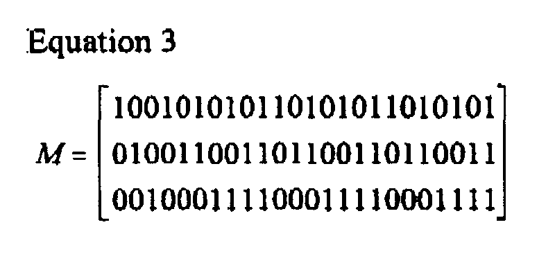
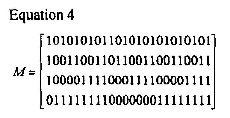


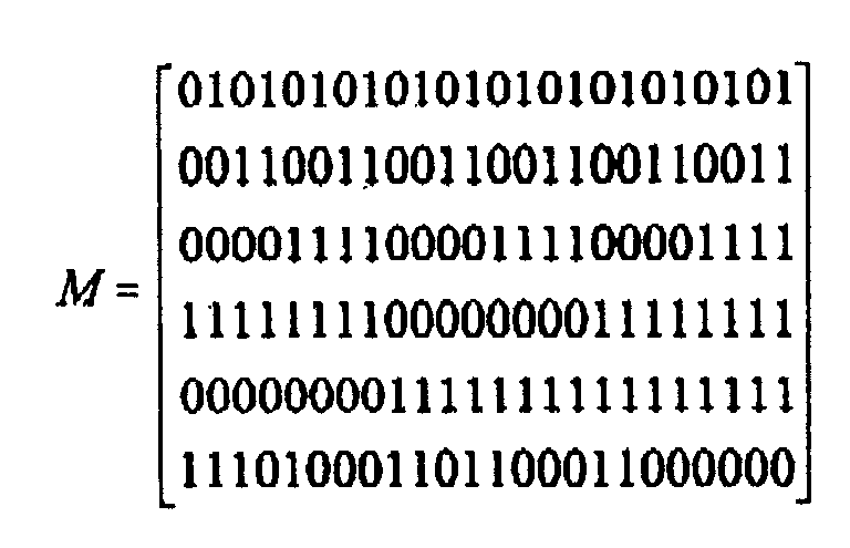


| No of Input Info Bits | Puncturing Positions |
| 1 | Even-numbered symbol positions and 1st, 3rd, 5th, 7th, 9th, 11th, 13th and 15th |
| 2 | 0th, 4th, 8th, 12th, 16th, 20th, 24th and 28th |
| 3 | 0th, 3rd, 5th, 6th, 7th, 8th, 16th and 24th |
| 4 | 0th, 1st, 2nd, 3rd, 4th, 5th, 6th and 16th |
| 5 | 0th, 1st, 2nd, 3rd, 4th, 5th, 6th and 7th symbol positions (or 0th, 4th, 8th, 12th, 16th, 20th, 24th and 28th symbol positions) |
| 6 | 0th, 1st, 2nd, 3rd, 4th, 5th, 6th and 7th symbol positions (or 0th, 4th, 8th, 12th, 16th, 20th, 24th and 28th symbol positions) |
| 7 | 0th, 1st, 2nd, 3rd, 4th, 5th, 6th and 7th symbol positions (or 0th, 4th, 8th, 12th, 16th, 20th, 24th and 28th symbol positions) |


| Input Information Bit | | |
| a0 | Multiplier | |
| 520 | ||
| | Multiplier | 522 |
| | Multiplier | 524 |
| | Multiplier | 526 |
| | Multiplier | 528 |
| | Multiplier | 530 |
| | Multiplier | 532 |
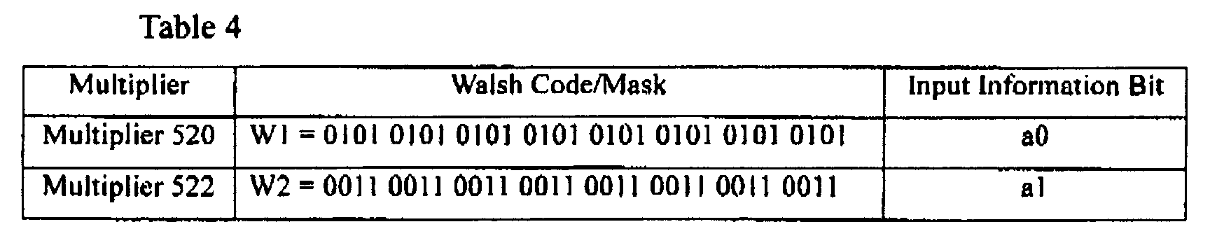
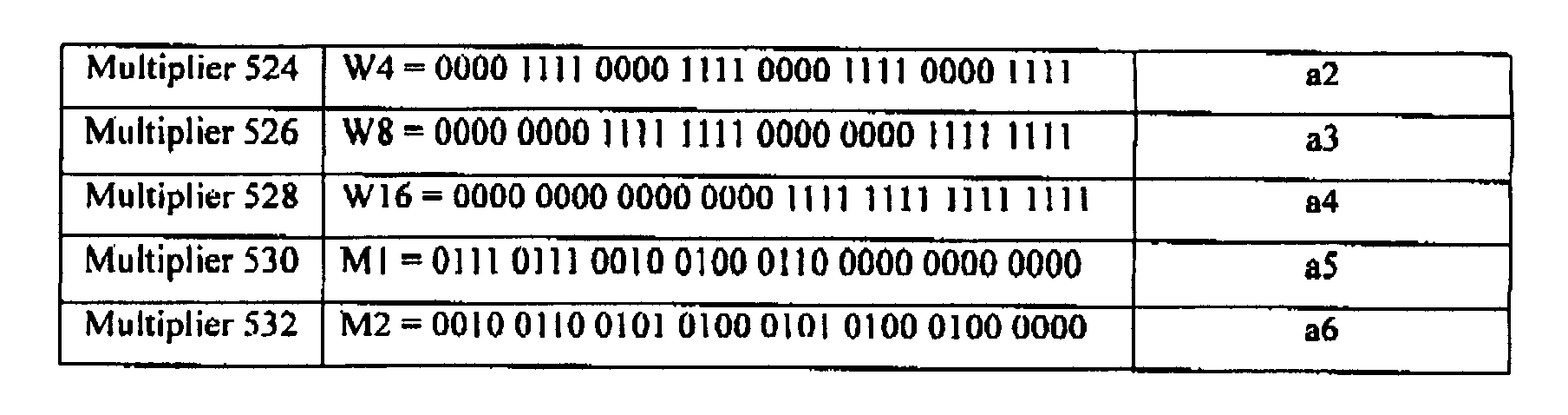
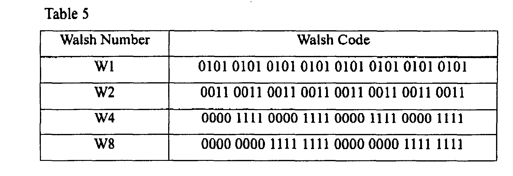

| Input Information Bit | | |
| A0 | Multiplier | |
| 520 | ||
| | Multiplier | 522 |
| | Multiplier | 524 |
| | Multiplier | 526 |
| | Multiplier | 528 |
| | Multiplier | 530 |
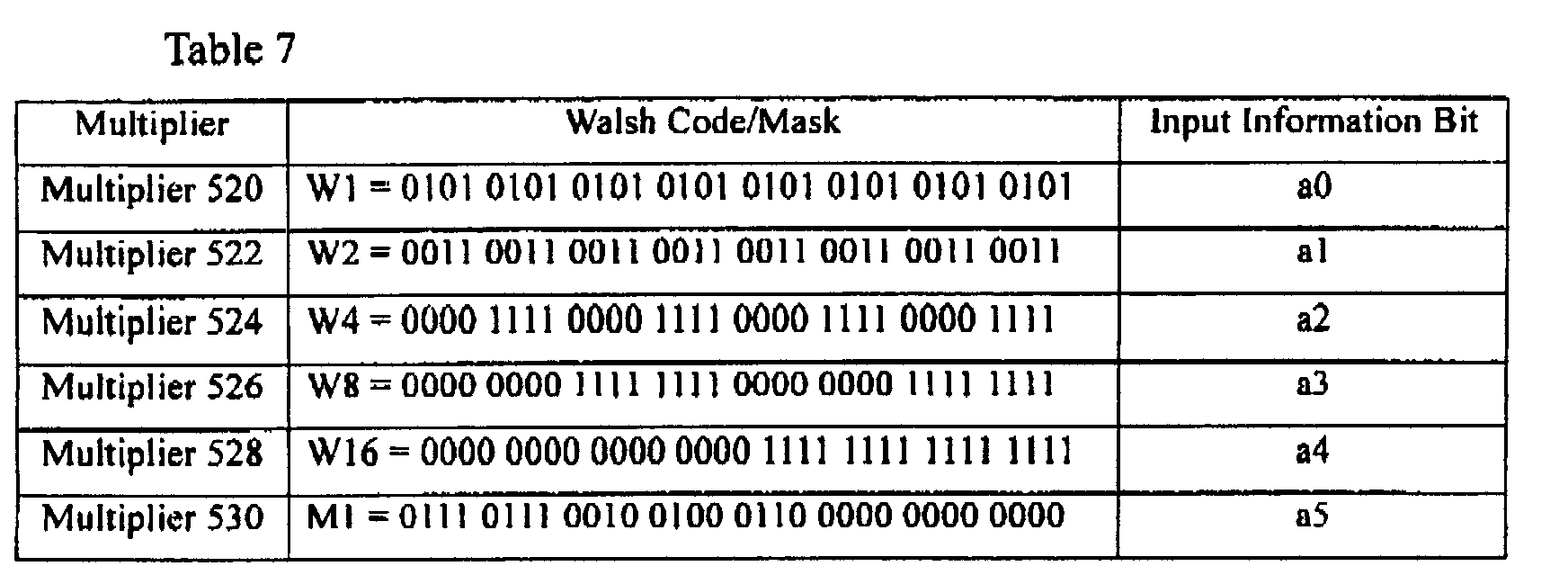
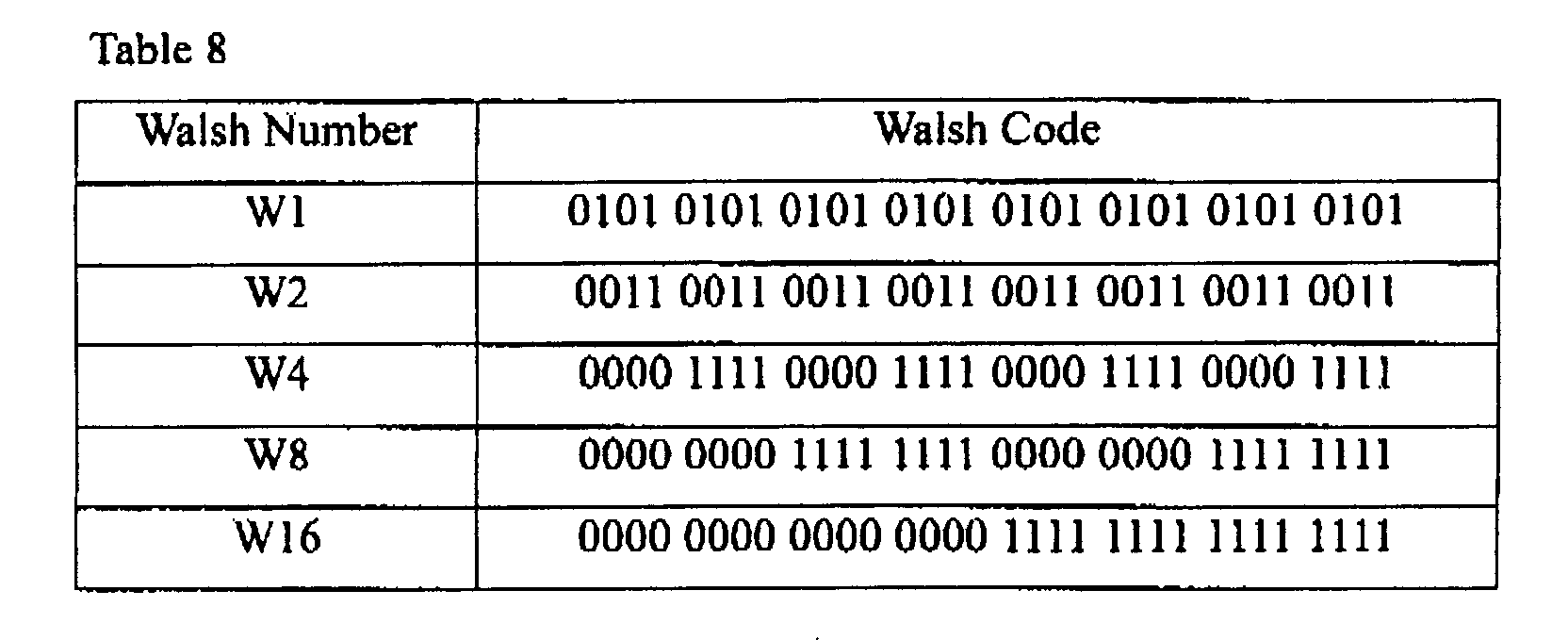
| Input Information Bit | | |
| a0 | Multiplier | |
| 520 | ||
| | Multiplier | 522 |
| | Multiplier | 524 |
| | Multiplier | 526 |
| | Multiplier | 528 |


| Input Information Bit | | |
| a0 | Multiplier | |
| 520 | ||
| | Multiplier | 522 |
| | Multiplier | 524 |
| | Multiplier | 526 |


| Input Information Bit | | |
| a0 | Multiplier | |
| 520 | ||
| | Multiplier | 522 |
| | Multiplier | 524 |
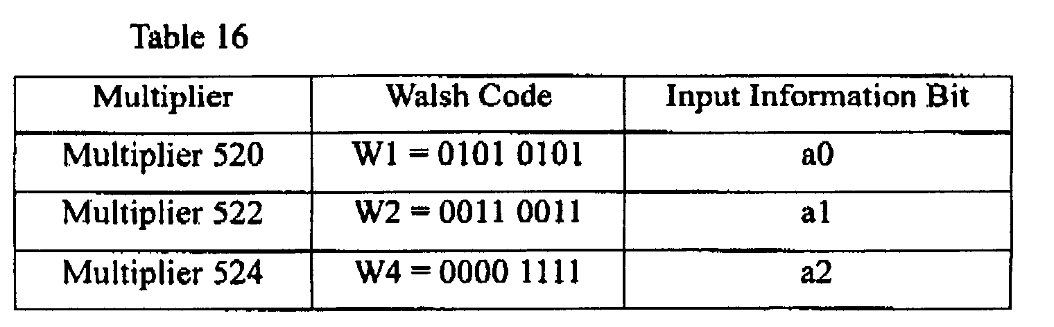
| Walsh Number | Walsh Code |
| W1 | 0101 |
| W2 | 0011 |
| Input Information Bit | | |
| a0 | Multiplier | |
| 520 | ||
| | Multiplier | 522 |
| Multiplier | Walsh Code | Input |
| Multiplier | ||
| 520 | W1 = 0101 | |
| Multiplier | ||
| 522 | W2 = 0011 | a1 |
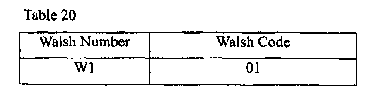
| Input Information Bit | |
| a0 | Multiplier |
| 520 |
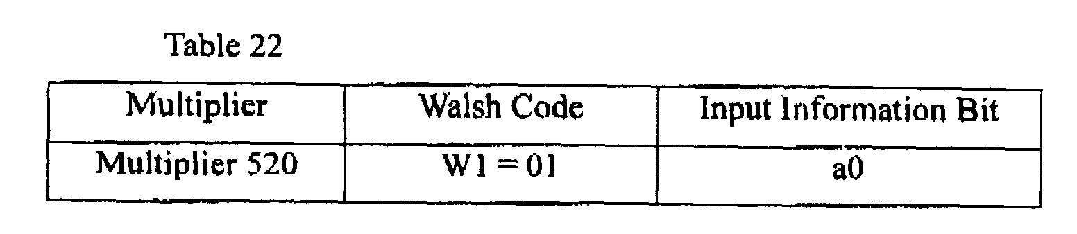
| No of Input Info Bits | Puncturing Positions |
| 1 | 1st, 3rd, 5th, 7th, 9th, 11th, 13th and 15th |
| 2 | 0th, 4th, 8th, 12th, 16th, 20th 24th and 28th |
| 3 | 0th, 3rd, 5th, 6th, 7th, 8th, 16th and 24th |
| 4 | 0th, 1st, 2nd, 3rd, 4th, 5th, 6th and 16th |
| 5 | 0th, 1st, 2nd, 3rd, 4th, 5th, 6th and 7th |
| 6 | 0th, 1st, 2nd, 3rd, 4th, 5th, 6th and 7th |
| 7 | 0th, 1st, 2nd, 3rd, 4th, 5th, 6th and 7th symbol positions |
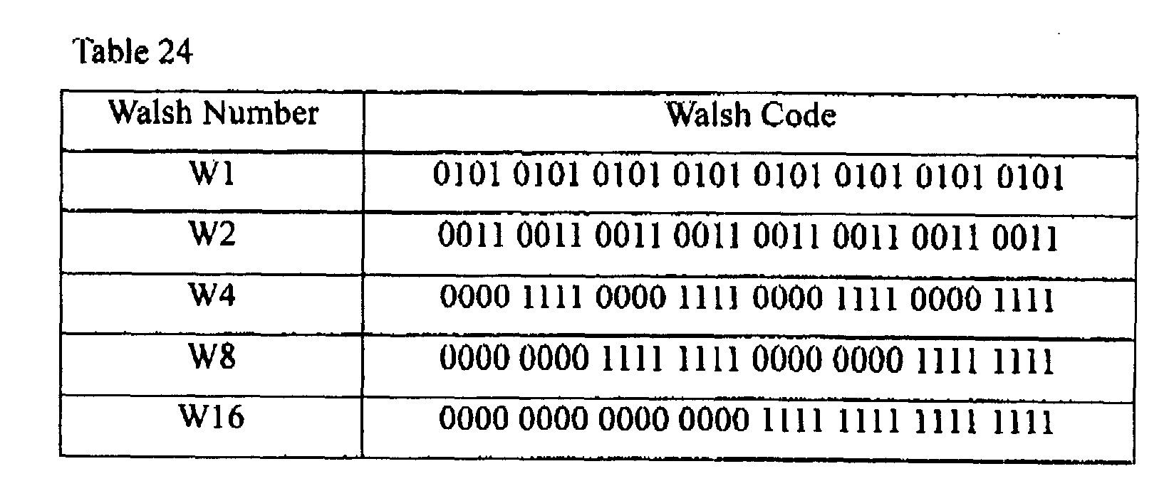
| Input Information Bit | | |
| a0 | Multiplier | |
| 1120 | ||
| | Multiplier | 1122 |
| | Multiplier | 1124 |
| | Multiplier | 1126 |
| | Multiplier | 1128 |
| | Multiplier | 1130 |
| | Multiplier | 1132 |
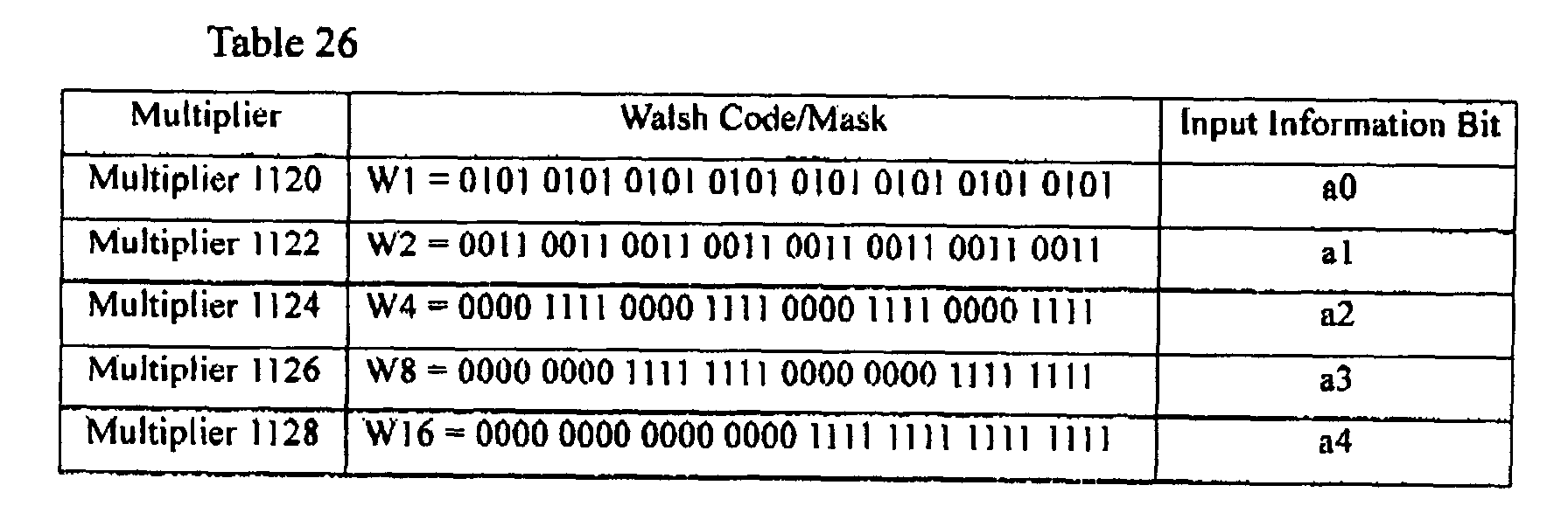



| Input Information Bit | | |
| a0 | Multiplier | |
| 1120 | ||
| | Multiplier | 1122 |
| | Multiplier | 1124 |
| | Multiplier | 1126 |
| | Multiplier | 1128 |
| | Multiplier | 1130 |

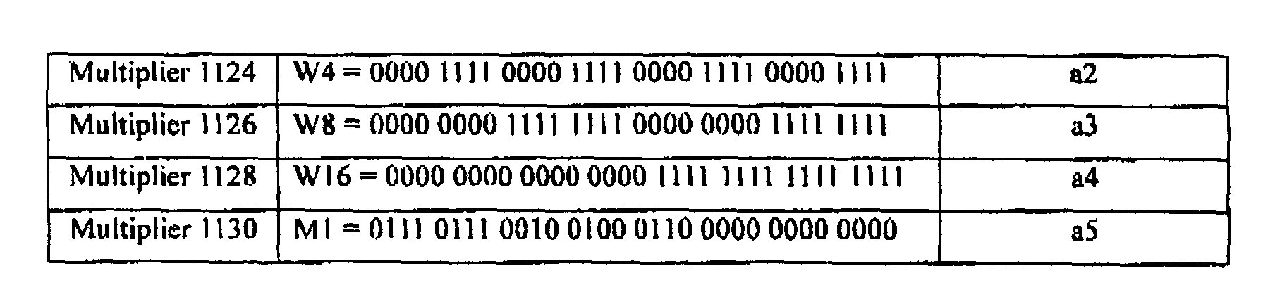

| Input Information Bit | | |
| a0 | Multiplier | |
| 1120 | ||
| | Multiplier | 1122 |
| | Multiplier | 1124 |
| | Multiplier | 1126 |
| | Multiplier | 1128 |
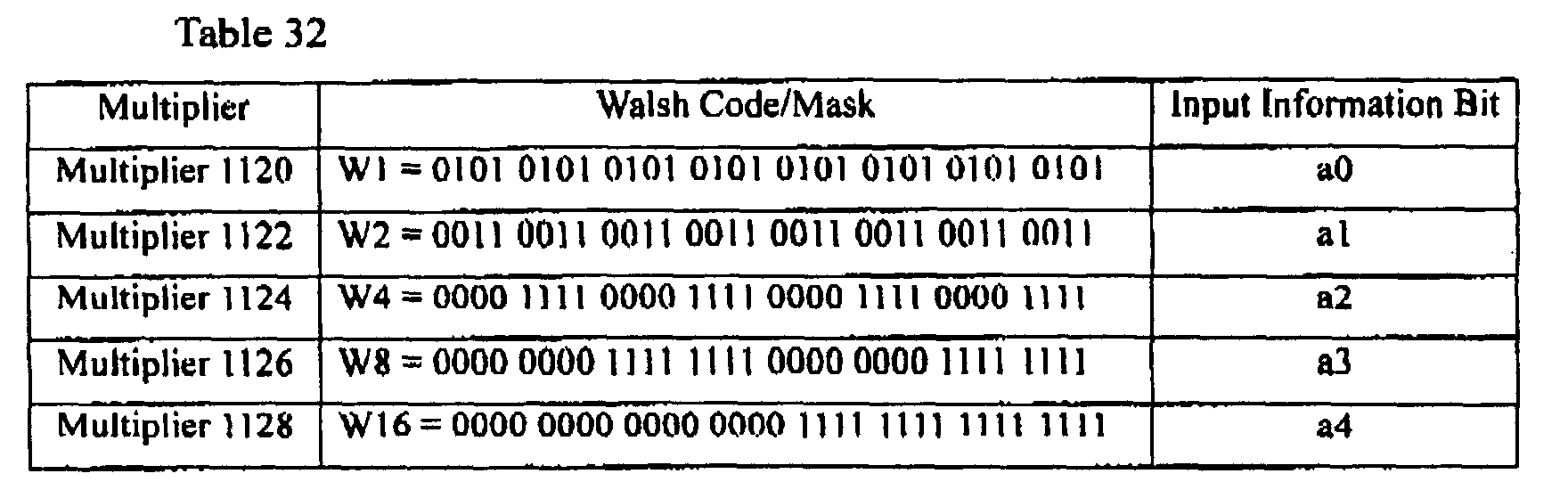

| Input Information Bit | | |
| a0 | Multiplier | |
| 1120 | ||
| | Multiplier | 1122 |
| | Multiplier | 1124 |
| | Multiplier | 1126 |
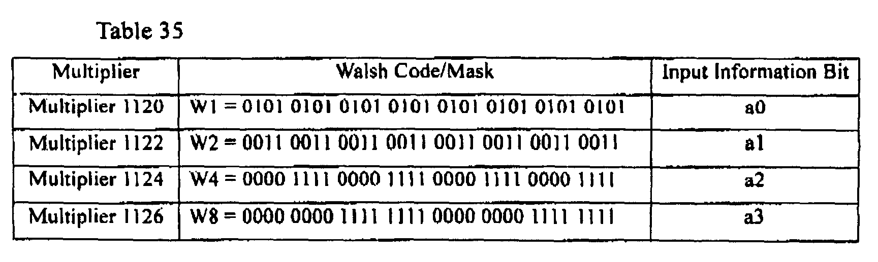
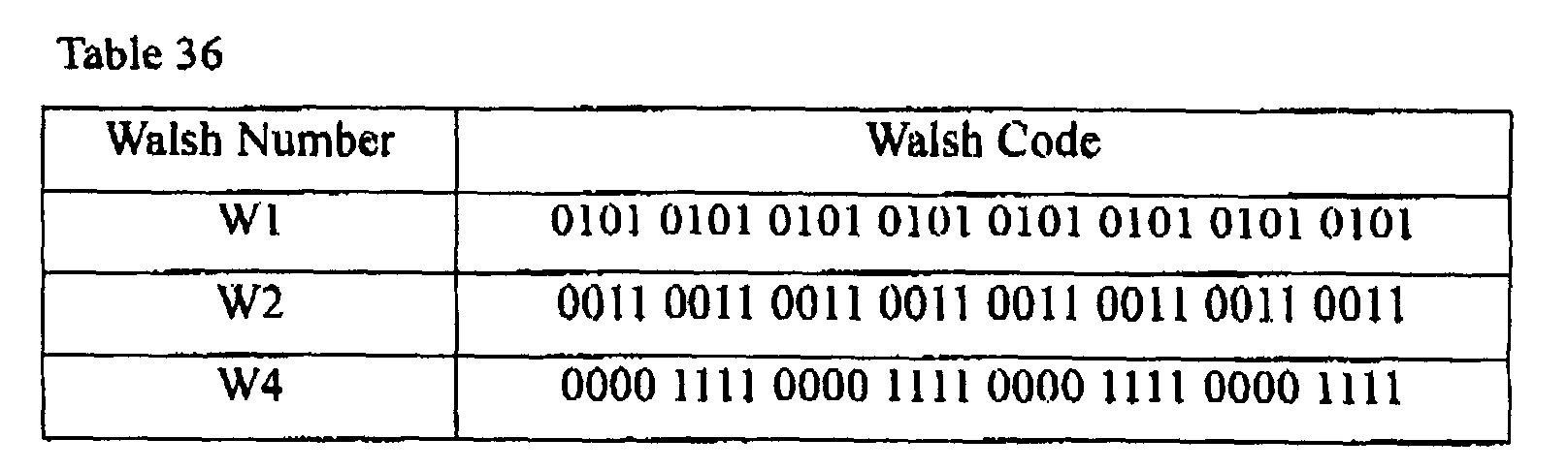
| Input Information Bit | | |
| a0 | Multiplier | |
| 1120 | ||
| | Multiplier | 1122 |
| | Multiplier | 1124 |

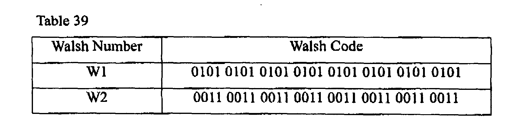
| Input Information Bit | | |
| a0 | Multiplier | |
| 1120 | ||
| | Multiplier | 1122 |



| Input Information Bit | |
| a0 | Multiplier |
| 1120 |

Claims (74)
- An encoding method in a mobile communication system, for receiving 1 to 7 input information bits and outputting a coded symbol stream having 24 coded symbols depending the input information bits, comprising the steps of:(a) encoding each of the input information bits with Walsh codes W1, W2,W4, W8 and W16 and masks M1 and M2 all having a predetermined length, and outputting a coded symbol stream having a predetermined number of coded symbols;(b) previously determining a plurality of sets of puncturing positions, each set corresponding to one of the each of possible number of the input information bits, and determining puncturing positions corresponding to the input information bits from the previously determined set of the puncturing positions ; and(c) puncturing coded symbols in the determined puncturing positions from the coded symbol stream having the predetermined number of coded symbols, and outputting the coded symbol stream having 24 coded symbols.
- The encoding method as claimed in claim 1, wherein the step (a) comprises the steps of:determining a length of the Walsh codes W1, W2, W4, W8 and W16 and the masks M1 and M2 depending on the input information bits, and outputting Walsh codes and masks corresponding to the input information bits selected in order among the Walsh codes W1, W2, W4, W8 and W16 and the masks M1 and M2;encoding the input information bits with the corresponding Walsh codes and masks, and outputting as many coded symbol streams as the input information bits;XORing the coded symbol streams to obtain one coded symbol stream; andrepeating the one coded symbol stream a predetermined number of times, and outputting the coded symbol stream having the predetermined number of coded symbols.
- The encoding method as claimed in claim 2, wherein when the number of the input information bits is 1, one Walsh code W1 of length 2 corresponding to the 1 input information bit is output.
- The encoding method as claimed in claim 3, wherein when the number of the input information bits is 1, the input information bit is encoded with the Walsh code W1 of length 2 to output a coded symbol stream, and the coded symbol stream is repeated 32 times thus to output a coded symbol stream having 64 coded symbols.
- The encoding method as claimed in claim 4, wherein when the number of the input information bits is 1, all of even-numbered symbol positions and 1st, 3rd, 5th, 7th, 9th, 11th, 13th and 15th symbol positions are determined as puncturing positions.
- The encoding method as claimed in claim 2, wherein when the number of the input information bits is 2, two Walsh codes W1 and W2 of length 4 corresponding to the 2 input information bits are output.
- The encoding method as claimed in claim 6, wherein when the number of the input information bits is 2, the input information bits are encoded with the 2 Walsh codes W1 and W2 of length 4 to output 2 coded symbol streams, and one coded symbol stream obtained by XORing the 2 coded symbol streams output is repeated 8 times to output a coded symbol stream having 32 coded symbols.
- The encoding method as claimed in claim 7, wherein when the number of the input information bits is 2, then 0th, 4th, 8th, 12th, 16th, 20th, 24th and 28th symbol positions are determined as puncturing positions.
- The encoding method as claimed in claim 2, wherein when the number of the input information bits is 3, three Walsh codes W1, W2 and W4 of length 8 corresponding to the 3 input information bits are output.
- The encoding method as claimed in claim 9, wherein when the number of the input information bits is 3, the input information bits are encoded with the 3 Walsh codes W1, W2 and W4 of length 8 to output 3 coded symbol streams, and one coded symbol stream obtained by XORing the 3 coded symbol streams is repeated 4 times to output a coded symbol stream having 32 coded symbols.
- The encoding method as claimed in claim 10, wherein when the number of the input information bits is 3, then 0th, 3rd, 5th, 6th, 7th, 8th, 16th and 24th symbol positions are determined as puncturing positions.
- The encoding method as claimed in claim 2, wherein when the number of the input information bits is 4, four Walsh codes W1, W2, W4 and W8 of length 16 corresponding to the 4 input information bits are output.
- The encoding method as claimed in claim 12, wherein when the number of the input information bits is 4, the input information bits are encoded with the 4 Walsh codes W1, W2, W4 and W8 of length 16 to output 4 coded symbol streams, and one coded symbol stream obtained by XORing the 4 coded symbol streams is repeated 2 times to output a coded symbol stream having 32 coded symbols.
- The encoding method as claimed in claim 13, wherein when the number of the input information bits is 4, then 0th, 1st, 2nd, 3rd, 4th, 5th, 6th and 16th symbol positions are determined as puncturing positions.
- The encoding method as claimed in claim 2, wherein when the number of the input information bits is 5, all of the Walsh codes W1, W2, W4, W8 and W16 of length 32 are output.
- The encoding method as claimed in claim 15, wherein when the number of the input information bits is 5, the input information bits are encoded with the 5 Walsh codes W1, W2, W4, W8 and W16 of length 32 to output 5 coded symbol streams, and the 5 coded symbol streams are XORed to output one coded symbol stream.
- The encoding method as claimed in claim 16, wherein when the number of the input information bits is 5, then 0th, 4th, 8th, 12th, 16th, 20th, 24th and 28th symbol positions are determined as puncturing positions.
- The encoding method as claimed in claim 16, wherein when the number of the input information bits is 5, then 0th, 1st, 2nd, 3rd, 4th, 5th, 6th and 7th symbol positions are determined as puncturing positions.
- The encoding method as claimed in claim 2, wherein when the number of the input information bits is 6, all of the Walsh codes W1, W2, W4, W8 and W16 of length 32 and one mask M1 of length 32 are output.
- The encoding method as claimed in claim 19, wherein when the number of the input information bits is 6, the input information bits are encoded with the 5 Walsh codes W1, W2, W4, W8 and W16 of length 32 and the mask M1 of length 32 to output 6 coded symbol streams, and the 6 coded symbol streams are XORed to output one coded symbol stream.
- The encoding method as claimed in claim 20, wherein when the number of the input information bits is 6, then the mask M1 is 0000 0000 1110 1000 1101 1000 1100 0000 and 0th, 4th, 8th, 12th, 16th, 20th, 24th and 28th symbol positions are determined as puncturing positions,
- The encoding method as claimed in claim 20, wherein when the number of the input information bits is 6, then the mask M1 is 0000 0000 1110 1000 1101 1000 1100 0000 and 0th, 1st, 2nd, 3rd, 4th, 5th, 6th and 7th symbol positions are determined as puncturing positions.
- The encoding method as claimed in claim 2, wherein when the number of the input information bits is 7, all of the Walsh codes W1, W2, W4, W8 and W16 of length 32 and two masks M1 and M2 of length 32 are output.
- The encoding method as claimed in claim 23, wherein when the number of the input information bits is 7, the input information bits are encoded with the 5 Walsh codes W1, W2, W4, W8 and W16 of length 32 and the 2 masks M1 and M2 of length 32 to output 7 coded symbol streams, and the 7 coded symbol streams are XORed to output one coded symbol stream.
- The encoding method as claimed in claim 24, wherein when the number of the input information bits is 7, then the mask M1 is 0111 0111 0010 0100 0110 0000 0000 0000, the mask M2 is 0010 0110 0101 0100 0101 0100 0100 0000, and 0th, 4th, 8th, 12th, 16th, 20th, 24th and 28th symbol positions are determined as puncturing positions.
- The encoding method as claimed in claim 24, wherein when the number of the input information bits is 7, then the mask M1 is 0111 0111 0010 0100 0110 0000 0000 0000, the mask M2 is 0010 0110 0101 0100 0101 0100 0100 0000, and 0th, 1st, 2nd, 3rd, 4th, 5th, 6th and 7th symbol positions are determined as puncturing positions.
- The encoding method as claimed in claim 1, wherein the Walsh codes W1, W2, W4, W8 and W16 and the masks M1 and M2 all have a predetermined length of 32.
- The encoding method as claimed in claim 27, wherein coded symbol streams determined by encoding the input information bits with the corresponding Walsh codes W1, W2, W4, W8 and W16 or the masks M1 and M2 are XORed to output one coded symbol stream, and the puncturing positions depending on the number of the input information bits are as follows.
No of Input Info Bits Puncturing Positions 1 1st, 3rd, 5th, 7th, 9th, 11th, 13th and 15th symbol positions 2 0th, 4th, 8th, 12th, 16th, 20th 24th and 28th symbol positions 3 0th, 3rd, 5th, 6th, 7th, 8th, 16th and 24th symbol positions 4 0th, 1st, 2nd, 3rd, 4th, 5th, 6th and 16th symbol positions 5 0th, 1st, 2nd, 3rd, 4th, 5th, 6th and 7th symbol positions 6 0th, 1st, 2nd, 3rd, 4th, 5th, 6th and 7th symbol positions 7 0th, 1st, 2nd, 3rd, 4th, 5th, 6th and 7th symbol positions - The encoding method as claimed in claim 27, wherein coded symbol streams determined by encoding the input information bits with the corresponding Walsh codes W1, W2, W4, W8 and W16 or the masks M1 and M2 are XORed to output one coded symbol stream, and the puncturing positions depending on the number of the input information bits are as follows.
No of Input Info Bits Puncturing Positions 1 1st, 3rd, 5th, 7th, 9th, 11th, 13th and 15th symbol positions 2 0th, 4th, 8th, 12th, 16th, 20th, 24th and 28th symbol positions 3 0th, 3rd, 5th, 6th, 7th, 8th, 16th and 24th symbol positions 4 0th, 1st, 2nd, 3rd, 4th, 5th, 6th and 16th symbol positions 5 0th, 4th, 8th, 12th, 16th, 20th, 24th and 28th symbol positions 6 0th, 4th, 8th, 12th, 16th, 20th, 24th and 28th symbol positions 7 0th, 4th, 8th, 12th, 16th, 20th, 24th and 28th symbol positions - The encoding method as claimed in claim 27, wherein the masks M1 and M2 generated for 7 input information bits are 0111 0111 0010 0100 0110 0000 0000 0000 and 0010 0110 0101 0100 0101 0100 0100 0000, respectively.
- The encoding method as claimed in claim 27, wherein the mask M1 generated for 6 input information bits is 0111 0111 0010 0100 0110 0000 0000 0000.
- An encoding apparatus in a mobile communication system, for receiving 1 to 7 input information bits and outputting a coded symbol stream having 24 coded symbols depending on the input information bits, comprising:a Walsh code generator for generating 5 different Walsh codes W1, W2, W4, W8 and W16 having a predetermined length;a mask generator for generating 2 different masks M1 and M2;a plurality of multipliers for multiplying the input information bits by a corresponding one selected from the Walsh codes W1, W2, W4, W8 and W16 and the masks M1 and M2 on a one-to-one basis and outputting a predetermined number of coded symbol streams;an XOR operator for XORing the coded symbol streams output from the multipliers and outputting one coded symbol stream; anda puncturer for determining puncturing positions corresponding to the input information bits, the puncturing positions selected for the input information bits from a plurality of sets of puncturing positions corresponding to each of the possible number of the input information bits, puncturing coded symbols in the determined puncturing positions from the coded symbol stream from the XOR operator, and outputting the coded symbol stream having 24 coded symbols.
- The encoding apparatus as claimed in claim 32, further comprising a repeater for repeating the coded symbol stream from the XOR operator a predetermined number of times so that the coded symbol stream from the XOR operator has a desired number of coded symbols.
- The encoding apparatus as claimed in claim 33, further comprising a controller for determining a length of the Walsh codes W1, W2, W4, W8 and W16 and the masks M1 and M2 depending on the number of the input information bits, controlling the Walsh code generator and the mask generator to output the Walsh codes and the masks corresponding to each of the numbers of the input information bits, and determining a repetition frequency of the repeater and the puncturing positions.
- The encoding apparatus as claimed in claim 34, wherein when the number of the input information bits is 1, the controller controls the Walsh code generator to generate a Walsh code W1 of length 2 corresponding to the 1 input information bit , and controls the repeater to repeat the coded symbol stream from the XOR operator 32 times.
- The encoding apparatus as claimed in claim 35, wherein the puncturer punctures all of even-numbered coded symbols and 1st, 3rd, 5th, 7th, 9th, 11th, 13th and 15th coded symbols among 64 coded symbols from the repeater under the control of the controller, and outputs the coded symbol stream of 24 coded symbols.
- The encoding apparatus as claimed in claim 34, wherein when the number of the input information bits is 2, the controller controls the Walsh code generator to generate two Walsh codes W1 and W2 of length 4 corresponding to the 2 input information bits , and controls the repeater to repeat the coded symbol stream from the XOR operator 8 times.
- The encoding apparatus as claimed in claim 37, wherein the puncturer punctures 0th, 4th, 8th, 12th, 16th, 20th, 24th and 28th coded symbols among 32 coded symbols from the repeater under the control of the controller, and outputs the coded symbol stream of 24 coded symbols.
- The encoding apparatus as claimed in claim 34, wherein when the number of the input information bits is 3, the controller controls the Walsh code generator to generate 3 Walsh codes W1, W2 and W4 of length 8 corresponding to the 3 input information bits, and controls the repeater to repeat the coded symbol stream from the XOR operator 4 times.
- The encoding apparatus as claimed in claim 39, wherein the punctures punctures 0th, 3rd, 5th, 6th, 7th, 8th, 16th and 24th coded symbols among 32 coded symbols from the repeater under the control of the controller, and outputs the coded symbol stream of 24 coded symbols.
- The encoding apparatus as claimed in claim 34, wherein when the number of the input information bits is 4, the controller controls the Walsh code generator to generate 4 Walsh codes W1, W2, W4 and W8 of length 16 corresponding to the 4 input information bits , and controls the repeater to repeat the coded symbol stream from the XOR operator 2 times.
- The encoding apparatus as claimed in claim 41, wherein the puncturer punctures 0th, 1st, 2nd, 3rd, 4th, 5th, 6th and 16th coded symbols among 32 coded symbols from the repeater under the control of the controller, and outputs the coded symbol stream of 24 coded symbols.
- The encoding apparatus as claimed in claim 34, wherein when the number of the input information bits is 5, the controller controls the Walsh code generator to generate all of the Walsh codes W1, W2, W4, W8 and W16 of length 32, and controls the repeater not to repeat the coded symbol stream from the XOR operator.
- The encoding apparatus as claimed in claim 43, wherein the puncturer punctures 0th, 4th, 8th, 12th, 16th, 20th, 24th and 28th coded symbols among 32 coded symbols from the repeater under the control of the controller, and outputs the coded symbol stream of 24 coded symbols,
- The encoding apparatus as claimed in claim 43, wherein the puncturer punctures 0th, 1st, 2nd, 3rd, 4th, 5th, 6th and 7th coded symbols among 32 coded symbols from the repeater under the control of the controller, and outputs the coded symbol stream of 24 coded symbols.
- The encoding apparatus as claimed in claim 34, wherein when the number of the input information bits is 6, the controller controls the Walsh code generator to generate all of the Walsh codes W1, W2, W4, W8 and W16 of length 32, controls the mask generator to generate one mask M1 of length 32, and controls the repeater not to repeat the coded symbol stream from the XOR operator.
- The encoding apparatus as claimed in claim 46, wherein the mask M1 generated by the mask generator is 0000 0000 1110 1000 1101 1000 1100 0000.
- The encoding apparatus as claimed in claim 47, wherein the puncturer punctures 0th, 4th, 8th, 12th, 16th, 20th, 24th and 28th coded symbols among 32 coded symbols from the repeater under the control of the controller, and outputs the coded symbol stream of 24 coded symbols.
- The encoding apparatus as claimed in claim 47, wherein the puncturer punctures 0th, 1st, 2nd, 3rd, 4th, 5th, 6th and 7th coded symbols among 32 coded symbols from the repeater under the control of the controller, and outputs the coded symbol stream of 24 coded symbols.
- The encoding apparatus as claimed in claim 34, wherein when the number of the input information bits is 7, the controller controls the Walsh code generator to generate all of the Walsh codes W1, W2, W4, W8 and W16 of length 32, controls the mask generator to generate 2 masks M1 and M2 of length 32, and controls the repeater not to repeat the coded symbol stream from the XOR operator.
- The encoding apparatus as claimed in claim 50, wherein the mask M1 generated by the mask generator is 0111 0111 0010 0100 0110 0000 0000 0000.
- The encoding apparatus as claimed in claim 51, wherein the puncturer punctures 0th, 4th, 8th, 12th, 16th, 20th, 24th and 28th coded symbols among 32 coded symbols from the repeater under the control of the controller, and outputs the coded symbol stream of 24 coded symbols.
- The encoding apparatus as claimed in claim 51, wherein the puncturer punctures 0th, 1st, 2nd, 3rd, 4th, 5th, 6th and 7th coded symbols among 32 coded symbols from the repeater under the control of the controller, and outputs the coded symbol stream of 24 coded symbols.
- The encoding apparatus as claimed in claim 32, wherein the Walsh codes W1, W2, W4, W8 and W16 and the masks M1 and M2 all have a length of 32.
- The encoding apparatus as claimed in claim 54, wherein puncturing positions corresponding to the number of the input information bits are as follows.
No of Input Info Bits Puncturing Positions 1 1st, 3rd, 5th, 7th, 9th, 11th, 13th and 15th symbol positions 2 0th, 4th, 8th, 12th, 16th, 20th 24th and 28th symbol positions 3 0th, 3rd, 5th, 6th, 7th, 8th, 16th and 24th symbol positions 4 0th, 1st, 2nd, 3rd, 4th, 5th, 6th and 16th symbol positions 5 0th, 1st, 2nd, 3rd, 4th, 5th, 6th and 7th symbol positions 6 0th, 1st, 2nd, 3rd, 4th, 5th, 6th and 7th symbol positions 7 0th, 1st, 2nd, 3rd, 4th, 5th, 6th and 7th symbol positions - The encoding apparatus as claimed in claim 54, wherein puncturing positions corresponding to the number of the input information bits are as follows.
No of Input Info Bits Puncturing Positions 1 1st, 3rd, 5th, 7th, 9th, 11th, 13th and 15th symbol positions 2 0th, 4th, 8th, 12th, 16th, 20th, 24th and 28th symbol positions 3 0th, 3rd, 5th, 6th, 7th, 8th, 16th and 24th symbol positions 4 0th, 1st, 2nd, 3rd, 4th, 5th, 6th and 16th symbol positions 5 0th, 4th, 8th, 12th, 16th, 20th, 24th and 28th symbol positions 6 0th, 4th, 8th, 12th, 16th, 20th, 24th and 28th symbol positions 7 0th, 4th, 8th, 12th, 16th, 20th, 24th and 28th symbol positions - The encoding apparatus as claimed in claim 54, wherein if the number of the input information bits is 7, the masks M1 and M2 generated by the mask generator are 0111 0111 0010 0100 0110 0000 0000 0000 and 0010 0110 0101 0100 0101 0100 0100 0000, respectively.
- The encoding apparatus as claimed in claim 54, wherein if the number of the input information bits is 6, the mask M1 generated by the mask generator is 0111 0111 0010 0100 0110 0000 0000 0000.
- A decoding method in a mobile communication system, for receiving a coded symbol stream having 24 coded symbols and outputting 1 to 7 input information bits from the coded symbol stream, comprising the steps of:determining puncturing positions according to length information of the input information bits;inserting zero (0) in the determined puncturing positions for the coded symbol stream received and outputting a coded symbol stream having a predetermined number of coded symbols;measuring correlation values of the zero-inserted coded symbol stream by those Walsh codes W1, W2, W4, W8 and W16 and those masks M1 and M2 having a length determined depending on the length information of the input information bits; andoutputting the input information bits from the measured correlation values.
- The decoding method as claimed in claim 59, wherein puncturing positions depending on the length information of the input information bits are as follows.
No of Input Info Bits Puncturing Positions 1 Even-numbered symbol positions and 1st, 3rd, 5th, 7th, 9th, 11th, 13th and 15th symbol positions 2 0th, 4th, 8th, 12th, 16th, 20th 24th and 28th symbol positions 3 0th, 3rd, 5th, 6th, 7th, 8th, 16th and 24th symbol positions 4 0th, 1st, 2nd, 3rd, 4th, 5th, 6th and 16th symbol positions 5 0th, 1st, 2nd, 3rd, 4th, 5th, 6th and 7th symbol positions 6 0th, 1st, 2nd, 3rd, 4th, 5th, 6th and 7th symbol positions 7 0th, 1st, 2nd, 3rd, 4th, 5th, 6th and 7th symbol positions - The decoding method as claimed in claim 59, wherein puncturing positions depending on the length information of the input information bits are as follows.
No of Input Info Bits Puncturing Positions 1 Even-numbered symbol positions and 1st, 3rd, 5th, 7th, 9th, 11th, 13th and 15th symbol positions 2 0th, 4th, 8th, 12th, 16th, 20th, 24th and 28th symbol positions 3 0th, 3rd, 5th, 6th, 7th, 8th, 16th and 24th symbol positions 4 0th, 1st, 2nd, 3rd, 4th, 5th, 6th and 16th symbol positions 5 0th, 4th, 8th, 12th, 16th, 20th, 24th and 28th symbol positions 6 0th, 4th, 8th, 12th, 16th, 20th, 24th and 28th symbol positions 7 0th, 4th, 8th, 12th, 16th, 20th, 24th and 28th symbol positions - The decoding method as claimed in claim 59, wherein lengths of those Walsh codes W1, W2, W4, W8 and W16 and those masks M1 and M2, determined depending on the length information of the input information bits, are as follows.
Length Info of Input Info Bits Length of Walsh Codes and Masks 1 bit 2 2 bits 4 3 bits 8 4 bits 16 5 bits 32 6 bits 32 7 bits 32 - The decoding method as claimed in claim 62, further comprising the step of accumulating coded symbols of the zero-inserted coded symbol stream in a unit of a length of those Walsh codes W1, W2, W4, W8 and W16 and those masks M1 and M2, and outputting as many accumulated coded symbols as the length of those Walsh codes and the masks.
- The decoding method as claimed in claim 59, wherein the zero-inserted coded symbol stream has 32 coded symbols.
- The decoding method as claimed in claim 64, wherein puncturing positions depending on the length information of the input information bits are as follows.
No of Input Info Bits Puncturing Positions 1 1st, 3rd, 5th, 7th, 9th, 11th, 13th and 15th symbol positions 2 0th, 4th, 8th, 12th, 16th, 20th 24th and 28th symbol positions 3 0th, 3rd, 5th, 6th, 7th, 8th, 16th and 24th symbol positions 4 0th, 1st, 2nd, 3rd, 4th, 5th, 6th and 16th symbol positions 5 0th, 1st, 2nd, 3rd, 4th, 5th, 6th and 7th symbol positions 6 0th, 1st, 2nd, 3rd, 4th, 5th, 6th and 7th symbol positions 7 0th, 1st, 2nd, 3rd, 4th, 5th, 6th and 7th symbol positions - The decoding method as claimed in claim 64, wherein puncturing positions depending on the length information of the input information bits are as follows.
No of Input Info Bits Puncturing Positions 1 1st, 3rd, 5th, 7th, 9th, 11th, 13th and 15th symbol positions 2 0th, 4th, 8th, 12th, 16th, 20th, 24th and 28th symbol positions 3 0th, 3rd, 5th, 6th, 7th, 8th, 16th and 24th symbol positions 4 0th, 1st, 2nd, 3rd, 4th, 5th, 6th and 16th symbol positions 5 0th, 4th, 8th, 12th, 16th, 20th, 24th and 28th symbol positions 6 0th, 4th, 8th, 12th, 16th, 20th, 24th and 28th symbol positions 7 0th, 4th, 8th, 12th, 16th, 20th, 24th and 28th symbol positions - A decoding apparatus in a mobile communication system, for receiving a coded symbol stream having 24 coded symbols and outputting 1 to 7 input information bits from the coded symbol stream, comprising:a zero inserter for inserting zero (0) in different puncturing positions of the coded symbol stream depending on length information of the input information bits;a correlation measurer for measuring correlation values of the zero-inserted coded symbol stream by those Walsh codes W1, W2, W4, W8 and W16 and those masks M1 and M2 having a length determined depending on the length information of the input information bits; anda correlation comparator for outputting the input information bits from the measured correlation values.
- The decoding apparatus as claimed in claim 67, wherein puncturing positions depending on the length information of the input information bits are as follows.
No of Input Info Bits Puncturing Positions 1 Even-numbered symbol positions and 1st, 3rd, 5th, 7th, 9th, 11th, 13th and 15th symbol positions 2 0th, 4th, 8th, 12th, 16th, 20th 24th and 28th symbol positions 3 0th, 3rd, 5th, 6th, 7th, 8th, 16th and 24th symbol positions 4 0th, 1st, 2nd, 3rd, 4th, 5th, 6th and 16th symbol positions 5 0th, 1st, 2nd, 3rd, 4th, 5th, 6th and 7th symbol positions 6 0th, 1st, 2nd, 3rd, 4th, 5th, 6th and 7th symbol positions 7 0th, 1st, 2nd, 3rd, 4th, 5th, 6th and 7th symbol positions - The decoding apparatus as claimed in claim 67, wherein puncturing positions depending on the length information of the input information bits are as follows.
No of Input Info Bits Puncturing Positions 1 Even-numbered symbol positions and 1st, 3rd, 5th, 7th, 9th, 11th, 13th and 15th symbol positions 2 0th, 4th, 8th, 12th, 16th, 20th, 24th and 28th symbol positions 3 0th, 3rd, 5th, 6th, 7th, 8th, 16th and 24th symbol positions 4 0th, 1st, 2nd, 3rd, 4th, 5th, 6th and 16th symbol positions 5 0th, 4th, 8th, 12th, 16th, 20th, 24th and 28th symbol positions 6 0th, 4th, 8th, 12th, 16th, 20th, 24th and 28th symbol positions 7 0th, 4th, 8th, 12th, 16th, 20th, 24th and 28th symbol positions - The decoding apparatus as claimed in claim 67, wherein lengths of those Walsh codes W1, W2, W4, W8 and W16 and those masks M1 and M2, determined depending on the length information of the input information bits, are as follows.
Length Info of Input Info Bits Length of Walsh Codes and Masks 1 bit 2 2 bits 4 3 bits 8 4 bits 16 5 bits 32 6 bits 32 7 bits 32 - The decoding apparatus as claimed in claim 70, further comprising a symbol accumulator for accumulating coded symbols of the zero-inserted coded symbol stream in a unit of a length of those Walsh codes W1, W2, W4, W8 and W16 and those masks M1 and M2, and outputting as many accumulated coded symbols as the length of those Walsh codes and those masks.
- The decoding apparatus as claimed in claim 67, wherein the zero-inserted coded symbol stream has 32 coded symbols.
- The decoding apparatus as claimed in claim 72, wherein puncturing positions depending on the length information of the input information bits are as follows.
No of Input Info Bits Puncturing Positions 1 1st, 3rd, 5th, 7th, 9th, 11th, 13th and 15th symbol positions 2 0th, 4th, 8th, 12th, 16th, 20th 24th and 28th symbol positions 3 0th, 3rd, 5th, 6th, 7th, 8th, 16th and 24th symbol positions 4 0th, 1st, 2nd, 3rd, 4th, 5th, 6th and 16th symbol positions 5 0th, 1st, 2nd, 3rd, 4th, 5th, 6th and 7th symbol positions 6 0th, 1st, 2nd, 3rd, 4th, 5th, 6th and 7th symbol positions 7 0th, 1st, 2nd, 3rd, 4th, 5th, 6th and 7th symbol positions - The decoding apparatus as claimed in claim 72, wherein puncturing positions depending on the length information of the input information bits are as follows.
No of Input Info Bits Puncturing Positions 1 1st, 3rd, 5th, 7th, 9th, 11th, 13th and 15th symbol positions 2 0th, 4th, 8th, 12th, 16th, 20th, 24th and 28th symbol positions 3 0th, 3rd, 5th, 6th, 7th, 8th, 16th and 24th symbol positions 4 0th, 1st, 2nd, 3rd, 4th, 5th, 6th and 16th symbol positions 5 0th, 4th, 8th, 12th, 16th, 20th, 24th and 28th symbol positions 6 0th, 4th, 8th, 12th, 16th, 20th, 24th and 28th symbol positions 7 0th, 4th, 8th, 12th, 16th, 20th, 24th and 28th symbol positions
Applications Claiming Priority (2)
| Application Number | Priority Date | Filing Date | Title |
|---|---|---|---|
| KR20010025306A KR100724847B1 (en) | 2001-05-09 | 2001-05-09 | Apparatus and method for encoding and decoding in code division multiple access mobile communication system |
| KR2001025306 | 2001-05-09 |
Publications (3)
| Publication Number | Publication Date |
|---|---|
| EP1257080A2 true EP1257080A2 (en) | 2002-11-13 |
| EP1257080A3 EP1257080A3 (en) | 2003-12-03 |
| EP1257080B1 EP1257080B1 (en) | 2006-06-21 |
Family
ID=36686656
Family Applications (1)
| Application Number | Title | Priority Date | Filing Date |
|---|---|---|---|
| EP20020010614 Expired - Lifetime EP1257080B1 (en) | 2001-05-09 | 2002-05-10 | Encoding/decoding apparatus and method in a CDMA mobile communication system |
Country Status (12)
| Country | Link |
|---|---|
| US (1) | US7146557B2 (en) |
| EP (1) | EP1257080B1 (en) |
| JP (1) | JP3860123B2 (en) |
| KR (1) | KR100724847B1 (en) |
| CN (1) | CN1262072C (en) |
| AU (1) | AU2002307676B2 (en) |
| BR (1) | BR0205218A (en) |
| CA (1) | CA2414304C (en) |
| DE (2) | DE60212497D1 (en) |
| GB (1) | GB2378365B (en) |
| RU (1) | RU2250563C2 (en) |
| WO (1) | WO2002091591A1 (en) |
Families Citing this family (21)
| Publication number | Priority date | Publication date | Assignee | Title |
|---|---|---|---|---|
| KR100834662B1 (en) * | 2001-11-21 | 2008-06-02 | 삼성전자주식회사 | Coding apparatus and method in code division multiple access mobile communication system |
| US7155236B2 (en) | 2003-02-18 | 2006-12-26 | Qualcomm Incorporated | Scheduled and autonomous transmission and acknowledgement |
| US8150407B2 (en) | 2003-02-18 | 2012-04-03 | Qualcomm Incorporated | System and method for scheduling transmissions in a wireless communication system |
| US7660282B2 (en) | 2003-02-18 | 2010-02-09 | Qualcomm Incorporated | Congestion control in a wireless data network |
| US8391249B2 (en) | 2003-02-18 | 2013-03-05 | Qualcomm Incorporated | Code division multiplexing commands on a code division multiplexed channel |
| US20040160922A1 (en) | 2003-02-18 | 2004-08-19 | Sanjiv Nanda | Method and apparatus for controlling data rate of a reverse link in a communication system |
| US8705588B2 (en) | 2003-03-06 | 2014-04-22 | Qualcomm Incorporated | Systems and methods for using code space in spread-spectrum communications |
| US7215930B2 (en) | 2003-03-06 | 2007-05-08 | Qualcomm, Incorporated | Method and apparatus for providing uplink signal-to-noise ratio (SNR) estimation in a wireless communication |
| KR20040085545A (en) * | 2003-03-31 | 2004-10-08 | 삼성전자주식회사 | Apparatus for decoding error correction doe in communication system and method thereof |
| US8477592B2 (en) | 2003-05-14 | 2013-07-02 | Qualcomm Incorporated | Interference and noise estimation in an OFDM system |
| US8489949B2 (en) | 2003-08-05 | 2013-07-16 | Qualcomm Incorporated | Combining grant, acknowledgement, and rate control commands |
| US7133690B2 (en) * | 2004-01-23 | 2006-11-07 | Nokia Corporation | Method and apparatus for fast data rate ramp up in Node B scheduling of UE uplink |
| US8780944B2 (en) * | 2005-08-26 | 2014-07-15 | Qualcomm Incorporated | Method and apparatus for reliable signaling in wireless communication |
| US8385433B2 (en) * | 2005-10-27 | 2013-02-26 | Qualcomm Incorporated | Linear precoding for spatially correlated channels |
| KR101066151B1 (en) | 2006-08-17 | 2011-09-20 | 인터디지탈 테크날러지 코포레이션 | Method and apparatus for providing efficient precoding feedback in a MIO wireless communication system |
| EP2553982B1 (en) * | 2010-04-01 | 2016-06-08 | Telefonaktiebolaget LM Ericsson (publ) | System and method for signaling control information in a mobile communication network |
| CN103401637B (en) * | 2013-07-15 | 2017-02-08 | 北京交大微联科技有限公司 | Transponder group message encoding and decoding method adopting distributed fountain code |
| KR101776267B1 (en) * | 2015-02-24 | 2017-09-07 | 삼성전자주식회사 | Transmitter and repetition method thereof |
| US10103912B1 (en) * | 2016-04-22 | 2018-10-16 | Ervin A Paw | Phased information pulse method and apparatus |
| CN109565484B (en) * | 2016-08-10 | 2021-02-09 | 华为技术有限公司 | Common synchronization signal for new wireless carriers supporting different subcarrier spacings |
| US12301347B2 (en) | 2021-09-15 | 2025-05-13 | Samsung Display Co., Ltd. | Systems and methods for transition encoding compatible PAM4 encoding |
Family Cites Families (17)
| Publication number | Priority date | Publication date | Assignee | Title |
|---|---|---|---|---|
| US5471497A (en) * | 1993-11-01 | 1995-11-28 | Zehavi; Ephraim | Method and apparatus for variable rate signal transmission in a spread spectrum communication system using coset coding |
| US5383219A (en) * | 1993-11-22 | 1995-01-17 | Qualcomm Incorporated | Fast forward link power control in a code division multiple access system |
| US5497395A (en) | 1994-04-04 | 1996-03-05 | Qualcomm Incorporated | Method and apparatus for modulating signal waveforms in a CDMA communication system |
| US5511082A (en) | 1994-05-10 | 1996-04-23 | General Instrument Corporation Of Delaware | Punctured convolutional encoder |
| JPH0918450A (en) * | 1995-06-27 | 1997-01-17 | Sony Corp | Code division multiplexing transmitter |
| US5909434A (en) * | 1996-05-31 | 1999-06-01 | Qualcomm Incorporated | Bright and burst mode signaling data transmission in an adjustable rate wireless communication system |
| US6101176A (en) * | 1996-07-24 | 2000-08-08 | Nokia Mobile Phones | Method and apparatus for operating an indoor CDMA telecommunications system |
| KR100387078B1 (en) * | 1997-07-30 | 2003-10-22 | 삼성전자주식회사 | Apparatus and method for puncturing and recovering symbol in band-spreading communication system |
| US6810030B1 (en) * | 1997-10-17 | 2004-10-26 | Lucent Technology | Dynamic and smart spreading for wideband CDMA |
| JP2000032561A (en) | 1998-07-08 | 2000-01-28 | Canon Inc | Wireless communication device, communication control method, and storage medium |
| US6351460B1 (en) * | 1999-05-24 | 2002-02-26 | Qualcomm Incorporated | Method and apparatus for a dedicated control channel in an early soft handoff in a code division multiple access communication system |
| EP2242192B1 (en) | 1999-07-06 | 2018-09-12 | Samsung Electronics Co., Ltd. | Apparatus and method for encoding/decoding transport format combination indicator in CDMA mobile communication system |
| JP3344373B2 (en) | 1999-07-09 | 2002-11-11 | 日本電気株式会社 | Mobile packet communication system |
| US6961387B2 (en) * | 2000-09-21 | 2005-11-01 | Samsung Electronics Co., Ltd. | Apparatus and method for coding/decoding optimal (11,5) codeword in a mobile communication system |
| US6714599B1 (en) * | 2000-09-29 | 2004-03-30 | Qualcomm, Incorporated | Method and apparatus for efficient processing of signal in a communication system |
| KR100434470B1 (en) * | 2000-10-09 | 2004-06-05 | 삼성전자주식회사 | Apparatus and method for tfci bits coding and decoding |
| US7293224B2 (en) * | 2001-03-20 | 2007-11-06 | Samsung Electronics Co., Ltd. | Encoding/decoding apparatus and method in a CDMA mobile communication system |
-
2001
- 2001-05-09 KR KR20010025306A patent/KR100724847B1/en not_active Expired - Fee Related
-
2002
- 2002-05-08 GB GB0210491A patent/GB2378365B/en not_active Expired - Fee Related
- 2002-05-09 CA CA002414304A patent/CA2414304C/en not_active Expired - Fee Related
- 2002-05-09 US US10/142,809 patent/US7146557B2/en not_active Expired - Fee Related
- 2002-05-09 WO PCT/KR2002/000860 patent/WO2002091591A1/en not_active Ceased
- 2002-05-09 AU AU2002307676A patent/AU2002307676B2/en not_active Ceased
- 2002-05-09 JP JP2002587936A patent/JP3860123B2/en not_active Expired - Fee Related
- 2002-05-09 BR BR0205218A patent/BR0205218A/en not_active IP Right Cessation
- 2002-05-09 RU RU2003100097A patent/RU2250563C2/en not_active IP Right Cessation
- 2002-05-09 CN CNB028021266A patent/CN1262072C/en not_active Expired - Fee Related
- 2002-05-10 EP EP20020010614 patent/EP1257080B1/en not_active Expired - Lifetime
- 2002-05-10 DE DE60212497T patent/DE60212497D1/en not_active Expired - Lifetime
- 2002-05-10 DE DE20207424U patent/DE20207424U1/en not_active Expired - Lifetime
Also Published As
| Publication number | Publication date |
|---|---|
| GB2378365B (en) | 2003-10-15 |
| KR20020085674A (en) | 2002-11-16 |
| US7146557B2 (en) | 2006-12-05 |
| GB2378365A (en) | 2003-02-05 |
| EP1257080A3 (en) | 2003-12-03 |
| JP3860123B2 (en) | 2006-12-20 |
| CA2414304A1 (en) | 2002-11-14 |
| CN1262072C (en) | 2006-06-28 |
| CN1463498A (en) | 2003-12-24 |
| CA2414304C (en) | 2006-12-19 |
| RU2250563C2 (en) | 2005-04-20 |
| KR100724847B1 (en) | 2007-06-04 |
| DE20207424U1 (en) | 2002-11-14 |
| JP2004533162A (en) | 2004-10-28 |
| DE60212497D1 (en) | 2006-08-03 |
| GB0210491D0 (en) | 2002-06-12 |
| US20030043888A1 (en) | 2003-03-06 |
| EP1257080B1 (en) | 2006-06-21 |
| AU2002307676B8 (en) | 2002-11-18 |
| WO2002091591A1 (en) | 2002-11-14 |
| BR0205218A (en) | 2004-06-29 |
| AU2002307676B2 (en) | 2004-10-14 |
Similar Documents
| Publication | Publication Date | Title |
|---|---|---|
| EP1257080B1 (en) | Encoding/decoding apparatus and method in a CDMA mobile communication system | |
| AU2002307676A1 (en) | Encoding/decoding apparatus and method in a CDMA mobile communication system | |
| US7068638B2 (en) | Apparatus and method for coding/decoding TFCI bits in an asynchronous CDMA communication system | |
| EP1208654B1 (en) | Apparatus and method for encoding and decoding tfci in a mobile communication system | |
| JP3987508B2 (en) | Transmission rate information decoding apparatus and method for communication system | |
| US7447190B2 (en) | Channel coding/decoding apparatus and method for a CDMA mobile communication system | |
| CN100418311C (en) | Device and method for symbol mapping transmission format combination indicator bit | |
| US20080146177A1 (en) | Apparatus and method for transmitting tfci bits for a hard split mode in a cdma mobile communication system | |
| US7293224B2 (en) | Encoding/decoding apparatus and method in a CDMA mobile communication system | |
| US6961387B2 (en) | Apparatus and method for coding/decoding optimal (11,5) codeword in a mobile communication system | |
| US6877131B2 (en) | Apparatus and method for generating block code in a mobile communication system | |
| RU2231217C1 (en) | Coding/decoding device and method for mobile code-division multiple access (cdma) communication system | |
| RU2233540C2 (en) | Device and method for converting tfci indicator bits into characters for fixed division mode in cdma mobile communication system |
Legal Events
| Date | Code | Title | Description |
|---|---|---|---|
| PUAI | Public reference made under article 153(3) epc to a published international application that has entered the european phase |
Free format text: ORIGINAL CODE: 0009012 |
|
| 17P | Request for examination filed |
Effective date: 20020510 |
|
| AK | Designated contracting states |
Kind code of ref document: A2 Designated state(s): AT BE CH CY DE DK ES FI FR GB GR IE IT LI LU MC NL PT SE TR |
|
| AX | Request for extension of the european patent |
Free format text: AL;LT;LV;MK;RO;SI |
|
| PUAL | Search report despatched |
Free format text: ORIGINAL CODE: 0009013 |
|
| RIC1 | Information provided on ipc code assigned before grant |
Ipc: 7H 03M 13/29 B Ipc: 7H 04L 1/00 A Ipc: 7H 04L 1/08 B Ipc: 7H 03M 13/13 B |
|
| AK | Designated contracting states |
Kind code of ref document: A3 Designated state(s): AT BE CH CY DE DK ES FI FR GB GR IE IT LI LU MC NL PT SE TR |
|
| AX | Request for extension of the european patent |
Extension state: AL LT LV MK RO SI |
|
| 17Q | First examination report despatched |
Effective date: 20040304 |
|
| AKX | Designation fees paid |
Designated state(s): DE FI FR IT SE |
|
| GRAP | Despatch of communication of intention to grant a patent |
Free format text: ORIGINAL CODE: EPIDOSNIGR1 |
|
| GRAS | Grant fee paid |
Free format text: ORIGINAL CODE: EPIDOSNIGR3 |
|
| GRAA | (expected) grant |
Free format text: ORIGINAL CODE: 0009210 |
|
| AK | Designated contracting states |
Kind code of ref document: B1 Designated state(s): DE FI FR IT SE |
|
| PG25 | Lapsed in a contracting state [announced via postgrant information from national office to epo] |
Ref country code: IT Free format text: LAPSE BECAUSE OF FAILURE TO SUBMIT A TRANSLATION OF THE DESCRIPTION OR TO PAY THE FEE WITHIN THE PRESCRIBED TIME-LIMIT;WARNING: LAPSES OF ITALIAN PATENTS WITH EFFECTIVE DATE BEFORE 2007 MAY HAVE OCCURRED AT ANY TIME BEFORE 2007. THE CORRECT EFFECTIVE DATE MAY BE DIFFERENT FROM THE ONE RECORDED. Effective date: 20060621 |
|
| REF | Corresponds to: |
Ref document number: 60212497 Country of ref document: DE Date of ref document: 20060803 Kind code of ref document: P |
|
| PG25 | Lapsed in a contracting state [announced via postgrant information from national office to epo] |
Ref country code: DE Free format text: LAPSE BECAUSE OF FAILURE TO SUBMIT A TRANSLATION OF THE DESCRIPTION OR TO PAY THE FEE WITHIN THE PRESCRIBED TIME-LIMIT Effective date: 20060922 |
|
| REG | Reference to a national code |
Ref country code: SE Ref legal event code: TRGR |
|
| PLBE | No opposition filed within time limit |
Free format text: ORIGINAL CODE: 0009261 |
|
| STAA | Information on the status of an ep patent application or granted ep patent |
Free format text: STATUS: NO OPPOSITION FILED WITHIN TIME LIMIT |
|
| EN | Fr: translation not filed | ||
| 26N | No opposition filed |
Effective date: 20070322 |
|
| PG25 | Lapsed in a contracting state [announced via postgrant information from national office to epo] |
Ref country code: FR Free format text: LAPSE BECAUSE OF FAILURE TO SUBMIT A TRANSLATION OF THE DESCRIPTION OR TO PAY THE FEE WITHIN THE PRESCRIBED TIME-LIMIT Effective date: 20070504 |
|
| PG25 | Lapsed in a contracting state [announced via postgrant information from national office to epo] |
Ref country code: FR Free format text: LAPSE BECAUSE OF FAILURE TO SUBMIT A TRANSLATION OF THE DESCRIPTION OR TO PAY THE FEE WITHIN THE PRESCRIBED TIME-LIMIT Effective date: 20060621 |
|
| PGFP | Annual fee paid to national office [announced via postgrant information from national office to epo] |
Ref country code: FI Payment date: 20150422 Year of fee payment: 14 Ref country code: SE Payment date: 20150422 Year of fee payment: 14 |
|
| PG25 | Lapsed in a contracting state [announced via postgrant information from national office to epo] |
Ref country code: FI Free format text: LAPSE BECAUSE OF NON-PAYMENT OF DUE FEES Effective date: 20160510 |
|
| PG25 | Lapsed in a contracting state [announced via postgrant information from national office to epo] |
Ref country code: SE Free format text: LAPSE BECAUSE OF NON-PAYMENT OF DUE FEES Effective date: 20160511 |