EP1257041A2 - Rotor for an alternator of an automotive vehicle - Google Patents
Rotor for an alternator of an automotive vehicle Download PDFInfo
- Publication number
- EP1257041A2 EP1257041A2 EP02009966A EP02009966A EP1257041A2 EP 1257041 A2 EP1257041 A2 EP 1257041A2 EP 02009966 A EP02009966 A EP 02009966A EP 02009966 A EP02009966 A EP 02009966A EP 1257041 A2 EP1257041 A2 EP 1257041A2
- Authority
- EP
- European Patent Office
- Prior art keywords
- hook portion
- flange
- coil
- rotor
- finishing end
- Prior art date
- Legal status (The legal status is an assumption and is not a legal conclusion. Google has not performed a legal analysis and makes no representation as to the accuracy of the status listed.)
- Granted
Links
Images


Classifications
-
- H—ELECTRICITY
- H02—GENERATION; CONVERSION OR DISTRIBUTION OF ELECTRIC POWER
- H02K—DYNAMO-ELECTRIC MACHINES
- H02K19/00—Synchronous motors or generators
- H02K19/16—Synchronous generators
- H02K19/22—Synchronous generators having windings each turn of which co-operates alternately with poles of opposite polarity, e.g. heteropolar generators
-
- H—ELECTRICITY
- H02—GENERATION; CONVERSION OR DISTRIBUTION OF ELECTRIC POWER
- H02K—DYNAMO-ELECTRIC MACHINES
- H02K3/00—Details of windings
- H02K3/46—Fastening of windings on the stator or rotor structure
- H02K3/52—Fastening salient pole windings or connections thereto
- H02K3/527—Fastening salient pole windings or connections thereto applicable to rotors only
- H02K3/528—Fastening salient pole windings or connections thereto applicable to rotors only of the claw-pole type
Definitions
- the present invention relates to a rotor for a vehicular alternating current generator mounted on passenger cars, trucks, and the like.
- a field coil is wound around an insulating bobbin.
- the insulating bobbin has a coil-winding body around which the field coil is wound and flanges extending from both ends of the coil-winding body in a radially outward direction.
- One of the flanges has a first hook portion and a second hook portion to fix a coil winding finishing end that is extended from the outer peripheral surface of the field coil.
- the finishing end is extended in a radial direction along an axial end surface of the flange through the first hook portion, and extended further in the axial direction through the second hook portion.
- the second hook portion is positioned radially inside of the outer periphery of the field coil. Since the finishing end is held at a position where centrifugal force is small, the finishing end is fixed to the flange with adequate strength against the centrifugal force.
- the finishing end is bent to form an angle with itself of substantially 90 degrees at the first hook portion. Therefore, if the finishing end is moved during posttreatment such as connection of the terminal end of the finishing end, the movement is likely to be transmitted to the coil-winding part of the field coil. As a result, the field coil is likely to easily loosen.
- the present invention is made in view of the above problems, and it is an object to provide a rotor for a vehicular alternating current generator, the rotor being capable of restricting loosening of a field coil.
- a field core is press-fitted around a rotary shaft, and an insulating bobbin is fitted around the field core.
- the insulating bobbin has a cylindrical coil-winding body and a flange extending in a radially outward direction from an axial end of the coil-winding body.
- the flange has a first surface and a second surface opposite to each other. The first surface is on a side of the coil-winding body and the second surface is on an axial end of the bobbin.
- a field coil is wound around the coil-winding body of the bobbin.
- the flange is formed with a first hook portion, a second hook portion and a third hook portion.
- the first hook portion is to direct a coil winding finishing of the field coil opposite to a winding direction of the field coil.
- the second hook portion is to direct the finishing end further in a radially inward direction.
- the third hook portion is to direct the finishing end further in an axial direction.
- the finishing end is wound around the first hook portion and is opposed to the winding direction of the field coil axially outside of the bobbin, and directed in the radially inward direction with the second hook portion.
- the finishing end is extended in the radially inward direction along the second surface of the flange.
- the finishing end is directed further in the axial direction with the third hook portion. Accordingly, even if the finishing end hooked with the second and the third hook portions is moved axially outside of the bobbin, the movement of the finishing end is restricted at the first hook portion and not transmitted to a coil-winding part of the field coil. Therefore, the field coil is prevented from loosening.
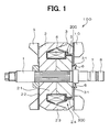
- a rotor 100 is rotatably supported by frames (not shown) of a vehicular alternating current generator (not shown) and driven by an engine (not shown) mounted on a vehicle.
- the rotor 100 is constructed of a rotary shaft 1, Lundell-type field cores 2 and 3 press-fitted around the rotary shaft 1, a field coil 4 wound around the field cores 2 and 3 through an insulating bobbin 5, and cooling fans 9 and 10 fixed to axial end surfaces of the field cores 2 and 3, respectivelly.
- Each of the field cores 2 and 3 has a boss part 21, radial parts 22 and claw pole pieces 23.
- the boss part 21 is coaxially arranged with the rotary shaft 1.
- the radial parts 22 extend from one of axial end surfaces of the boss part 21 in the radial direction.
- the claw pole pieces 23 extend from the outer peripheral parts of the radial parts 22 in the axial direction.
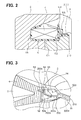
- a V-shaped groove 24 is defined between adjacent two of the radial parts 22, as shown in FIG. 3.
- the field cores 2 and 3 are assembled such that the plurality of claw pole pieces 23 is alternately intermeshed with each other.
- the field coil 4 wound around the insulating bobbin 5 is accommodated within a space surrounded with the boss parts 21, the radial parts 22 and the claw pole pieces 23.
- the insulating bobbin 5 has a cylindrical coil-winding body 51 and two flanges 52 and 56 extending from both axial ends of the coil winding body 51 in the radial direction, as shown in FIG. 2.
- the flange 52 is formed with two hook portions to hook a coil winding finishing end 200 and a coil winding starting end 300 of the field coil 4.
- One of the hook portions which is to hook the finishing end 200 extended from the field coil 4, has a first hook portion 53, a second hook portion 54, a third hook portion 55 and a V-shaped portion 52d.
- the finishing end 200 is drawn through these three hooks 53 to 55, and then arranged to extend along the axial end surface of the field core 3 which is arranged on a rear side (right side in FIG. 1).
- the finishing end 200 and the starting end 300 are pulled out of the bobbin 5 at positions axially symmetrical to each other with respect to the rotary shaft 1, as shown in FIG. 1.
- the finishing end 200 and the starting end 300 are extended from the field coil 4 and extended along the axial end surface of the flange 52 in the radial direction, respectively.
- the finishing end 200 and the starting end 300 are extended along the bottom of the grooves 24 of the field core 3 in the axial direction, respectively.
- the finishing end 200 and the starting end 300 are then extended in the radial direction through grooves 31 that are formed on the axial end surface of the field core 3 between the end surface of the field core 3 and the cooling fan 10.
- Two slip rings 7 and 8 are provided on one axial end side (right side in FIG. 1) of the rotary shaft 1 and electrically connected to a pair of connecting terminals 6.
- the finishing end 200 and the starting end 300 extended along the axial end surface of the field core 3 are connected to the terminals 6, respectively.
- the cooling fans 9 and 10 are fixed to the axial end surfaces of the field cores 2 and 3 by welding and the like.
- the cooling fans 9 and 10 generate cooling air for cooling a stator (not shown) and the like mounted in the vehicular alternating current generator with rotation of the rotor 100.
- a part of the flange 52 is exposed in a fan-shape (fan-shaped portion 52a) to the axial end side in the V-shaped groove 24 of the field core 3, as shown in FIG. 3.
- the first hook portion 53 protrudes from the outer peripheral surface of the fan-shaped portion 52a outwardly in the radial direction.
- the second hook portion 54 extends from a part of the fan-shaped portion 52a in the axial direction adjacent to the first hook portion 53, as shown in FIG. 4.
- the third hook portion 55 is formed along an axial end surface of the second hook portion 54 opposite to the flange to extend in the circumferential direction.
- the third hook portion 55 is in contact with the second hook portion 55.
- the third hook portion 55 extends substantially parallel to the fan-shaped portion 52a such that a space 52e is defined between the fan-shaped portion 52a and the third hook portion 55 to guide the finishing end 200 in the radial direction.
- the V-shaped portion 52d projects in the axial direction from the third hook portion 55 in the V-shaped groove 24 of the field core 3.
- the finishing end 200 of the field coil 4 is hooked on the hook portion of the flange 52 in the following manner.
- the finishing end 200 is wound around the first hook portion 53 from axially inside to axially outside of the bobbin 5, so that a portion 200a of the finishing end 200 is directed opposite to a coil-winding direction of the field coil 4 at axially outside of the first hook portion 53 of the bobbin 5.
- the finishing end 200 forms an angle with itself of less than 90 degrees (an acute angle) around the first hook portion 53 when viewed along an axial direction of the first hook portion 53.
- the finishing end 200 is then hooked with the second hook portion 54.
- the finishing end 200 is directed in the radially inward direction at the radially outer edge of the second hook portion 54.
- a portion 200b of the finishing end 200 is guided in the radially inward direction along the axial end surface of the fan-shaped portion 52a in the space 52e.
- finishing end 200 is hooked with the third hook portion 55.
- the finishing end 200 is directed in the axial direction at the radially inside of the third hook portion 55.
- a portion 200c of the finishing end 200 is extended in the axial direction along the bottom of the V-shaped portion 52d.
- the finishing end 200 is directed in the axial direction at radially inside of the outer peripheral end of the field coil 4.
- a portion 200d of the finishing end 200 is inserted in an insulating tube 210 and extended further in the radially inward direction in the groove 31. Then, the finishing end 200 is connected to the connecting terminal 6 by welding and the like.
- the starting end 300 of the field coil 4 is, for example, hooked in a slit (not shown) provided on the flange 52.
- the starting end 300 is connected to the remaining terminal 6 by welding and the like.
- a coil winding start portion of the field coil 4 is located radially inside of the field coil 4, the field coil 4 is not easily loosened due to movement of the starting end 300.
- At least half of the last turn of the field coil 4 is wound along the axially inner surface of the flange 52. Therefore, it becomes easy to wind the starting end 200 around the first hook portion 53 to form the acute angle with itself.
- An impregnated material 50 made of resin is pasted along the finishing end 200 and the starting end 300 extended through the above-described routes, so that the finishing end 200 and the starting end 300 are bonded to the insulating bobbin 5, as shown in FIG.5. Especially, the finishing end 200 is bent to extend along the hook portion. The impregnated material 50 is filled between the finishing end 200 and the insulating bobbin 5 at the bent portions of the finishing end 200 to bond therebetween. Accordingly, the finishing end 200 is tightly fixed to the bobbin 5.
- the finishing end 200 of the field coil 4 is wound around the first hook portion 53 to form the acute angle with itself when viewed along the axial direction of the first hook portion 53. Therefore, if the finishing end 200 extending in the radially inward direction through the second hook portion 54 or the third hook portion 55 is moved, that movement is restricted at the first hook portion 53 and is not transmitted to the coil winding part of the field coil 4. Therefore, the field coil 4 is restricted from loosening and expanding due to centrifugal force. As a result, breakage of the field coil 4 is prevented and the power generating problems is decreased. Accordingly, it is possible to increase reliability of the rotor 100 and the vehicular alternating current generator having the rotor 100.
- the V-shaped portion 52d located in the V-shaped groove 24 is replaced into a projected wall portion 152d.
- the projected wall portion 152d is formed to extend from the axial end surface of the third hook portion 55 in the axial direction.
- the projected wall portion 152d is not in a V-shape, but in a single wall extending along the surface 33b of the field core 3 in the V-shaped groove 24.
- the finishing end 200 can be easily fitted in a proper position. In this case, the surface 33a of the field core 3 is exposed. Therefore, it is preferable that the portion 200c of the finishing end 200 extended in the axial direction at the bottom of the V-shaped groove 24 is inserted in the insulating tube 210 from the axial outside of the third hook portion 55 to be securely insulated from the field core 3, as shown in FIG. 7.
- an outer shape of the first hook portion 53 and the second hook portion 54 are changed. Edges of the first hook portion 53 around which the finishing end 200 is wound are angled to be along the finishing end 200, as shown in FIG. 9.
- the axial length (width) of the second hook portion 54 is increased to enlarge the space 52e in which the finishing end 200 is extended in the radial direction.
- a curvature of radius of the finishing end 200 extending through the first hook portion 53, the second hook portion 54 and the third hook portion 55 is increased. Therefore, it is restricted that an insulating film of the finishing end 200 is damaged at the hook portions 53 to 55.
- each of the hooks 53 to 55 is affected by external force due to movement of the finishing end 200, stress generated on each hook is decreased. Therefore, damage on each hook is decreased, so reliability of the rotor is increased.
Landscapes
- Engineering & Computer Science (AREA)
- Power Engineering (AREA)
- Synchronous Machinery (AREA)
- Insulation, Fastening Of Motor, Generator Windings (AREA)
Abstract
Description
Claims (9)
- A rotor (100) for a vehicular alternating current generator comprising:characterized in that the flange (52) is formed with a first hook portion (53) that directs the finishing end (200) opposite to a winding direction of the field coil (4), a second hook portion (54) that directs the finishing end (200) further in a radially inward direction along the second surface of the flange (52) and a third hook portion (55) that directs the finishing end (200) further in an axial direction.a rotary shaft (1);a field core (2, 3) press-fitted around the rotary shaft (1);an insulating bobbin (5) fitted around the field core (2, 3), the insulating bobbin (5) having a cylindrical coil-winding body (51) and a flange (52) extending in a radially outward direction from an axial end of the coil-winding body (51), the flange (52) having a first surface and a second surface opposite to each other, the first surface being on a side of the coil-winding body (51) and the second surface being an axial end surface of the bobbin (5); anda field coil (4) wound around the coil-winding body (51) and having a coil winding finishing end (200),
- The rotor (100) for the vehicular alternating current generator according to claim 1, further characterized in that the finishing end (200) is wound around the first hook portion (53) and is opposed to the coil-winding direction of the field coil (4).
- The rotor (100) for the vehicular alternating current generator according to claim 1 or 2, further characterized in that the finishing end (200) is wound around the first hook portion (53) and placed axially outside of the bobbin (5), thereby forming an angle with itself of less than 90 degrees when viewed along an axial direction of the first hook portion (53).
- The rotor (100) for the vehicular alternating current generator according to any one of claims 1 to 3, further characterized in that the finishing end (200) is wound around the first hook portion (53), directed in a radially inward direction with the second hook portion (54), extended further in the radially inward direction along the second surface of the flange (52) and directed further in the axial direction with the third hook portion (55).
- The rotor (100) for the vehicular alternating current generator according to any one of claims 1 to 4, further characterized in that at least half of a last turn of the field coil (4) is wound around the coil-winding body (51) along the first surface of the flange (52).
- The rotor (100) for the vehicular alternating current generator according to any one of claims 1 to 5, further characterized in that the finishing end (200) is fixed to the flange (52) by an impregnated material (50).
- The rotor (100) for the vehicular alternating current generator according to any one of claims 1 to 6, further characterized in that the first hook portion (53) protrudes from an outer peripheral surface of the flange (52) in the radial direction, a second hook portion (54) extends from the second surface of the flange (52) adjacent to the first hook portion (53), and a third hook portion (55) is formed along an axial end surface opposite to the flange (52) on the second hook portion (54) and extends substantially parallel to the flange (52), thereby defining a space (52e) between the third hook portion (55) and the flange (52).
- The rotor (100) for the vehicular alternating current generator according to claim 7, further characterized in that the finishing end (200) is wound around the first hook portion (53) to oppose the winding direction of the field coil (4), directed in the radially inward direction at a radially outer end of the second hook portion (54), extended further in the space (52e) in the radially inward direction and directed further in the axial direction radially inside of the third hook portion (55).
- The rotor (100) for the vehicular alternating current generator according to claim 8, further characterized in that the finishing end (200) is directed in the axial direction at a position radially inside of an outer peripheral end of the field coil (4).
Applications Claiming Priority (2)
| Application Number | Priority Date | Filing Date | Title |
|---|---|---|---|
| JP2001139630A JP4048730B2 (en) | 2001-05-10 | 2001-05-10 | AC alternator rotor for vehicles |
| JP2001139630 | 2001-05-10 |
Publications (3)
| Publication Number | Publication Date |
|---|---|
| EP1257041A2 true EP1257041A2 (en) | 2002-11-13 |
| EP1257041A3 EP1257041A3 (en) | 2003-10-08 |
| EP1257041B1 EP1257041B1 (en) | 2006-03-22 |
Family
ID=18986374
Family Applications (1)
| Application Number | Title | Priority Date | Filing Date |
|---|---|---|---|
| EP02009966A Expired - Lifetime EP1257041B1 (en) | 2001-05-10 | 2002-05-03 | Rotor for an alternator of an automotive vehicle |
Country Status (6)
| Country | Link |
|---|---|
| US (1) | US6784577B2 (en) |
| EP (1) | EP1257041B1 (en) |
| JP (1) | JP4048730B2 (en) |
| KR (1) | KR100473616B1 (en) |
| CN (1) | CN100444501C (en) |
| DE (1) | DE60209958T2 (en) |
Cited By (3)
| Publication number | Priority date | Publication date | Assignee | Title |
|---|---|---|---|---|
| WO2009156288A1 (en) * | 2008-06-24 | 2009-12-30 | Robert Bosch Gmbh | Electric machine |
| FR3006517A1 (en) * | 2013-06-04 | 2014-12-05 | Valeo Equip Electr Moteur | ROTATING ELECTRIC MACHINE FOR MOTOR VEHICLE |
| EP2717436A4 (en) * | 2011-05-31 | 2016-05-11 | Mitsubishi Electric Corp | ROTOR OF ROTATING ELECTRIC MACHINE, AND ROTATING ELECTRIC MACHINE EQUIPPED WITH SUCH A ROTOR |
Families Citing this family (11)
| Publication number | Priority date | Publication date | Assignee | Title |
|---|---|---|---|---|
| JP2003079079A (en) * | 2001-09-03 | 2003-03-14 | Honda Motor Co Ltd | Power distribution ring for rotating electric machines |
| KR20080071344A (en) * | 2007-01-30 | 2008-08-04 | 삼성전자주식회사 | motor |
| JP4577386B2 (en) | 2008-03-19 | 2010-11-10 | 株式会社デンソー | Rotor of rotating electrical machine and method for manufacturing the same |
| JP4975165B2 (en) * | 2008-03-21 | 2012-07-11 | 三菱電機株式会社 | Rotating electric machine for vehicles |
| JP5132631B2 (en) * | 2009-05-25 | 2013-01-30 | 三菱電機株式会社 | Motor stator, motor, air conditioner, and motor manufacturing method |
| JP4903247B2 (en) * | 2009-07-23 | 2012-03-28 | 三菱電機株式会社 | Bobbin for winding and rotating electric machine |
| FR2952767B1 (en) * | 2009-11-13 | 2012-06-01 | Valeo Equip Electr Moteur | CLUTCH ROTOR EQUIPPED WITH AN INSULATION FOR EXCITATION WINDING AND MAGNETS AND ROTATING ELECTRICAL MACHINE EQUIPPED WITH SUCH A ROTOR |
| WO2014087461A1 (en) * | 2012-12-03 | 2014-06-12 | 三菱電機株式会社 | Rotor of rotating electrical machine and method for manufacturing same |
| US20140265710A1 (en) * | 2013-03-14 | 2014-09-18 | Remy Technologies Llc | Coil arrangement with intermediary wire tie-off |
| KR102579568B1 (en) * | 2015-11-12 | 2023-09-18 | 엘지이노텍 주식회사 | Busbar and Motor having the same |
| CN112820538B (en) * | 2021-04-16 | 2021-07-02 | 成都瑞迪智驱科技股份有限公司 | Electromagnetic coil winding processing device |
Family Cites Families (26)
| Publication number | Priority date | Publication date | Assignee | Title |
|---|---|---|---|---|
| US3603825A (en) * | 1970-05-21 | 1971-09-07 | Gen Motors Corp | Winding spool and lead support insulator for rotors of alternating current generators |
| US3963949A (en) * | 1972-10-26 | 1976-06-15 | General Electric Company | Laminated structure with insulating member formed in situ thereon |
| US4114056A (en) * | 1976-03-30 | 1978-09-12 | Nippondenso Co., Ltd. | Rotor for alternating current generator |
| US4217690A (en) * | 1978-06-23 | 1980-08-19 | Rapidsyn Co. | Method of assembly for electric motor stators |
| JPS5546858A (en) * | 1978-09-29 | 1980-04-02 | Hitachi Ltd | Rotor for inductor-type generator |
| US4407256A (en) * | 1980-07-24 | 1983-10-04 | Wabash, Inc. | Capacitor discharge ignition system and method of manufacture thereof |
| JPS6048365U (en) * | 1983-09-05 | 1985-04-05 | 三菱電機株式会社 | rotor of rotating electric machine |
| US4520288A (en) * | 1984-04-05 | 1985-05-28 | Briggs & Stratton Corp. | Ignition magneto having an improved primary winding construction |
| JPS6141382U (en) * | 1984-08-17 | 1986-03-15 | アルプス電気株式会社 | brushless motor |
| JPS6329378U (en) * | 1986-08-07 | 1988-02-26 | ||
| US5270604A (en) * | 1992-05-21 | 1993-12-14 | Ford Motor Company | Tandem field alternator having an improved coil and slip ring connection and method of making the same |
| KR0124817Y1 (en) * | 1994-09-08 | 1998-12-15 | 정몽원 | Rotor of automotive alternator |
| US5533252A (en) * | 1994-09-29 | 1996-07-09 | Kabushiki Kaisha Toshiba | Slot insulator guide in assembly of dynamoelectric machine and coil inserting apparatus provided therewith |
| JP3504352B2 (en) * | 1994-10-05 | 2004-03-08 | 三菱電機株式会社 | Vehicle alternator rotor |
| JPH08126261A (en) * | 1994-10-25 | 1996-05-17 | Mitsubishi Electric Corp | Vehicle alternator rotor |
| JPH09163700A (en) * | 1995-12-08 | 1997-06-20 | Mitsubishi Electric Corp | AC generator |
| US5698923A (en) * | 1996-05-24 | 1997-12-16 | Alliedsignal Inc. | Exciter stator insulating bobbin |
| JP3752770B2 (en) * | 1997-03-21 | 2006-03-08 | 株式会社デンソー | Landel core type rotary electric machine |
| JP2000083336A (en) * | 1998-09-04 | 2000-03-21 | Mitsubishi Electric Corp | Vehicle alternator rotor |
| JP3185879B2 (en) * | 1998-10-12 | 2001-07-11 | 株式会社デンソー | Vehicle alternator rotor |
| KR100293689B1 (en) * | 1999-05-15 | 2001-06-15 | 한규환 | fixing construction of alternator for vehicles |
| JP3904761B2 (en) * | 1999-05-27 | 2007-04-11 | 三菱電機株式会社 | AC alternator rotor for vehicles |
| JP3609649B2 (en) * | 1999-06-29 | 2005-01-12 | 三洋電機株式会社 | Brushless DC motor and refrigerant compressor using this motor |
| JP4046444B2 (en) * | 1999-07-16 | 2008-02-13 | 三菱電機株式会社 | AC generator for vehicles |
| US6509665B1 (en) * | 1999-10-25 | 2003-01-21 | Matsushita Electric Industial Co., Ltd. | Motor having stator with insulator of high heat-conductivity |
| US6590310B2 (en) * | 2001-02-21 | 2003-07-08 | Kabushiki Kaisha Moric | Stator coil structure for revolving-field electrical machine and method of manufacturing same |
-
2001
- 2001-05-10 JP JP2001139630A patent/JP4048730B2/en not_active Expired - Fee Related
-
2002
- 2002-05-03 EP EP02009966A patent/EP1257041B1/en not_active Expired - Lifetime
- 2002-05-03 DE DE60209958T patent/DE60209958T2/en not_active Expired - Lifetime
- 2002-05-08 KR KR10-2002-0025313A patent/KR100473616B1/en not_active Expired - Fee Related
- 2002-05-08 US US10/140,327 patent/US6784577B2/en not_active Expired - Lifetime
- 2002-05-10 CN CNB021191689A patent/CN100444501C/en not_active Expired - Fee Related
Cited By (7)
| Publication number | Priority date | Publication date | Assignee | Title |
|---|---|---|---|---|
| WO2009156288A1 (en) * | 2008-06-24 | 2009-12-30 | Robert Bosch Gmbh | Electric machine |
| EP2717436A4 (en) * | 2011-05-31 | 2016-05-11 | Mitsubishi Electric Corp | ROTOR OF ROTATING ELECTRIC MACHINE, AND ROTATING ELECTRIC MACHINE EQUIPPED WITH SUCH A ROTOR |
| FR3006517A1 (en) * | 2013-06-04 | 2014-12-05 | Valeo Equip Electr Moteur | ROTATING ELECTRIC MACHINE FOR MOTOR VEHICLE |
| WO2014195611A1 (en) * | 2013-06-04 | 2014-12-11 | Valeo Equipements Electriques Moteur | Electrical rotating machine for motor vehicle |
| CN105191072A (en) * | 2013-06-04 | 2015-12-23 | 法雷奥电机设备公司 | Electrical rotating machine for motor vehicle |
| CN105191072B (en) * | 2013-06-04 | 2019-07-05 | 法雷奥电机设备公司 | Rotating electric machine for motor vehicles |
| US10566868B2 (en) | 2013-06-04 | 2020-02-18 | Valeo Equipments Electriques Moteur | Rotary electrical machine for motor vehicle |
Also Published As
| Publication number | Publication date |
|---|---|
| DE60209958T2 (en) | 2007-03-15 |
| US6784577B2 (en) | 2004-08-31 |
| EP1257041B1 (en) | 2006-03-22 |
| CN100444501C (en) | 2008-12-17 |
| JP2002335661A (en) | 2002-11-22 |
| KR100473616B1 (en) | 2005-03-08 |
| KR20020086251A (en) | 2002-11-18 |
| EP1257041A3 (en) | 2003-10-08 |
| DE60209958D1 (en) | 2006-05-11 |
| CN1385942A (en) | 2002-12-18 |
| JP4048730B2 (en) | 2008-02-20 |
| US20020167233A1 (en) | 2002-11-14 |
Similar Documents
| Publication | Publication Date | Title |
|---|---|---|
| EP1257041A2 (en) | Rotor for an alternator of an automotive vehicle | |
| EP0961385A1 (en) | Ac generator for vehicle and method of manufacturing stator thereof | |
| EP0994552B1 (en) | Rotor for vehicular alternating current generator | |
| JP4697292B2 (en) | Rotating electrical machine rotor | |
| JP6459084B2 (en) | Rotating electric machine stator | |
| JP3836608B2 (en) | AC alternator rotor for vehicles | |
| EP1120883B1 (en) | Alternator | |
| WO2017126297A1 (en) | Rotary electric machine | |
| JP4734159B2 (en) | Manufacturing method of stator of rotating electric machine | |
| CN100365916C (en) | alternator | |
| JP6045267B2 (en) | AC generator for vehicles | |
| EP3373420B1 (en) | Rotor of rotating electric machine | |
| CN108292869B (en) | Claw pole rotor of a rotating electrical machine provided with at least one chamfer formed on the trailing edge of the claw | |
| JP4114282B2 (en) | Rotating electric machine and manufacturing method thereof | |
| JP3656347B2 (en) | Rotating machine rotor | |
| JP3541550B2 (en) | Electric motor | |
| CN108292870B (en) | Rotary electric machine claw rotor with enhanced magnetic properties | |
| CN108370182A (en) | Claw rotor of a rotating electrical machine having claws with curved chamfers | |
| JP7304165B2 (en) | electric compressor | |
| KR0184797B1 (en) | Rotor structure of automotive alternator | |
| EP3540913B1 (en) | Rotor of dynamo-electric machine | |
| JP2000245091A (en) | Vehicle alternator and method of manufacturing the same | |
| JPH11332139A (en) | Stator of motor | |
| KR20220093556A (en) | Motor |
Legal Events
| Date | Code | Title | Description |
|---|---|---|---|
| PUAI | Public reference made under article 153(3) epc to a published international application that has entered the european phase |
Free format text: ORIGINAL CODE: 0009012 |
|
| AK | Designated contracting states |
Kind code of ref document: A2 Designated state(s): AT BE CH CY DE DK ES FI FR GB GR IE IT LI LU MC NL PT SE TR |
|
| AX | Request for extension of the european patent |
Free format text: AL;LT;LV;MK;RO;SI |
|
| PUAL | Search report despatched |
Free format text: ORIGINAL CODE: 0009013 |
|
| AK | Designated contracting states |
Kind code of ref document: A3 Designated state(s): AT BE CH CY DE DK ES FI FR GB GR IE IT LI LU MC NL PT SE TR |
|
| AX | Request for extension of the european patent |
Extension state: AL LT LV MK RO SI |
|
| 17P | Request for examination filed |
Effective date: 20031120 |
|
| AKX | Designation fees paid |
Designated state(s): DE FR GB IT |
|
| 17Q | First examination report despatched |
Effective date: 20050222 |
|
| GRAP | Despatch of communication of intention to grant a patent |
Free format text: ORIGINAL CODE: EPIDOSNIGR1 |
|
| GRAS | Grant fee paid |
Free format text: ORIGINAL CODE: EPIDOSNIGR3 |
|
| GRAA | (expected) grant |
Free format text: ORIGINAL CODE: 0009210 |
|
| AK | Designated contracting states |
Kind code of ref document: B1 Designated state(s): DE FR GB IT |
|
| REG | Reference to a national code |
Ref country code: GB Ref legal event code: FG4D |
|
| REF | Corresponds to: |
Ref document number: 60209958 Country of ref document: DE Date of ref document: 20060511 Kind code of ref document: P |
|
| ET | Fr: translation filed | ||
| REG | Reference to a national code |
Ref country code: GB Ref legal event code: 746 Effective date: 20061025 |
|
| PLBE | No opposition filed within time limit |
Free format text: ORIGINAL CODE: 0009261 |
|
| STAA | Information on the status of an ep patent application or granted ep patent |
Free format text: STATUS: NO OPPOSITION FILED WITHIN TIME LIMIT |
|
| 26N | No opposition filed |
Effective date: 20061227 |
|
| PG25 | Lapsed in a contracting state [announced via postgrant information from national office to epo] |
Ref country code: IT Free format text: LAPSE BECAUSE OF NON-PAYMENT OF DUE FEES Effective date: 20100503 |
|
| PGRI | Patent reinstated in contracting state [announced from national office to epo] |
Ref country code: IT Effective date: 20141022 |
|
| REG | Reference to a national code |
Ref country code: FR Ref legal event code: PLFP Year of fee payment: 15 |
|
| REG | Reference to a national code |
Ref country code: FR Ref legal event code: PLFP Year of fee payment: 16 |
|
| REG | Reference to a national code |
Ref country code: FR Ref legal event code: PLFP Year of fee payment: 17 |
|
| PGFP | Annual fee paid to national office [announced via postgrant information from national office to epo] |
Ref country code: DE Payment date: 20180522 Year of fee payment: 17 |
|
| PGFP | Annual fee paid to national office [announced via postgrant information from national office to epo] |
Ref country code: IT Payment date: 20180530 Year of fee payment: 17 Ref country code: FR Payment date: 20180522 Year of fee payment: 17 |
|
| PGFP | Annual fee paid to national office [announced via postgrant information from national office to epo] |
Ref country code: GB Payment date: 20180518 Year of fee payment: 17 |
|
| REG | Reference to a national code |
Ref country code: DE Ref legal event code: R119 Ref document number: 60209958 Country of ref document: DE |
|
| GBPC | Gb: european patent ceased through non-payment of renewal fee |
Effective date: 20190503 |
|
| PG25 | Lapsed in a contracting state [announced via postgrant information from national office to epo] |
Ref country code: GB Free format text: LAPSE BECAUSE OF NON-PAYMENT OF DUE FEES Effective date: 20190503 Ref country code: DE Free format text: LAPSE BECAUSE OF NON-PAYMENT OF DUE FEES Effective date: 20191203 Ref country code: IT Free format text: LAPSE BECAUSE OF NON-PAYMENT OF DUE FEES Effective date: 20190503 |
|
| PG25 | Lapsed in a contracting state [announced via postgrant information from national office to epo] |
Ref country code: FR Free format text: LAPSE BECAUSE OF NON-PAYMENT OF DUE FEES Effective date: 20190531 |