EP1256868A2 - Grip for latching a cover to a receptacle - Google Patents
Grip for latching a cover to a receptacle Download PDFInfo
- Publication number
- EP1256868A2 EP1256868A2 EP20020252831 EP02252831A EP1256868A2 EP 1256868 A2 EP1256868 A2 EP 1256868A2 EP 20020252831 EP20020252831 EP 20020252831 EP 02252831 A EP02252831 A EP 02252831A EP 1256868 A2 EP1256868 A2 EP 1256868A2
- Authority
- EP
- European Patent Office
- Prior art keywords
- grip
- receiver
- thumb
- cover
- latching device
- Prior art date
- Legal status (The legal status is an assumption and is not a legal conclusion. Google has not performed a legal analysis and makes no representation as to the accuracy of the status listed.)
- Withdrawn
Links
Images




Classifications
-
- G—PHYSICS
- G06—COMPUTING OR CALCULATING; COUNTING
- G06F—ELECTRIC DIGITAL DATA PROCESSING
- G06F1/00—Details not covered by groups G06F3/00 - G06F13/00 and G06F21/00
- G06F1/16—Constructional details or arrangements
- G06F1/1613—Constructional details or arrangements for portable computers
- G06F1/1615—Constructional details or arrangements for portable computers with several enclosures having relative motions, each enclosure supporting at least one I/O or computing function
- G06F1/1616—Constructional details or arrangements for portable computers with several enclosures having relative motions, each enclosure supporting at least one I/O or computing function with folding flat displays, e.g. laptop computers or notebooks having a clamshell configuration, with body parts pivoting to an open position around an axis parallel to the plane they define in closed position
-
- E—FIXED CONSTRUCTIONS
- E05—LOCKS; KEYS; WINDOW OR DOOR FITTINGS; SAFES
- E05B—LOCKS; ACCESSORIES THEREFOR; HANDCUFFS
- E05B1/00—Knobs or handles for wings; Knobs, handles, or press buttons for locks or latches on wings
- E05B1/0038—Sliding handles, e.g. push buttons
-
- E—FIXED CONSTRUCTIONS
- E05—LOCKS; KEYS; WINDOW OR DOOR FITTINGS; SAFES
- E05B—LOCKS; ACCESSORIES THEREFOR; HANDCUFFS
- E05B5/00—Handles completely let into the surface of the wing
-
- G—PHYSICS
- G06—COMPUTING OR CALCULATING; COUNTING
- G06F—ELECTRIC DIGITAL DATA PROCESSING
- G06F1/00—Details not covered by groups G06F3/00 - G06F13/00 and G06F21/00
- G06F1/16—Constructional details or arrangements
- G06F1/1613—Constructional details or arrangements for portable computers
- G06F1/1633—Constructional details or arrangements of portable computers not specific to the type of enclosures covered by groups G06F1/1615 - G06F1/1626
- G06F1/1675—Miscellaneous details related to the relative movement between the different enclosures or enclosure parts
- G06F1/1679—Miscellaneous details related to the relative movement between the different enclosures or enclosure parts for locking or maintaining the movable parts of the enclosure in a fixed position, e.g. latching mechanism at the edge of the display in a laptop or for the screen protective cover of a PDA
-
- E—FIXED CONSTRUCTIONS
- E05—LOCKS; KEYS; WINDOW OR DOOR FITTINGS; SAFES
- E05B—LOCKS; ACCESSORIES THEREFOR; HANDCUFFS
- E05B73/00—Devices for locking portable objects against unauthorised removal; Miscellaneous locking devices
- E05B73/0082—Devices for locking portable objects against unauthorised removal; Miscellaneous locking devices for office machines, e.g. PC's, portable computers, typewriters, calculators
-
- Y—GENERAL TAGGING OF NEW TECHNOLOGICAL DEVELOPMENTS; GENERAL TAGGING OF CROSS-SECTIONAL TECHNOLOGIES SPANNING OVER SEVERAL SECTIONS OF THE IPC; TECHNICAL SUBJECTS COVERED BY FORMER USPC CROSS-REFERENCE ART COLLECTIONS [XRACs] AND DIGESTS
- Y10—TECHNICAL SUBJECTS COVERED BY FORMER USPC
- Y10T—TECHNICAL SUBJECTS COVERED BY FORMER US CLASSIFICATION
- Y10T292/00—Closure fasteners
- Y10T292/08—Bolts
- Y10T292/0911—Hooked end
- Y10T292/0926—Spring projected
- Y10T292/0928—Operating means
Definitions
- the invention relates generally to the field of latching devices and, more particularly, to devices used to latch a cover to a receptacle.
- a latch In a portable computing unit, a latch is often used to secure the cover of the computing unit to another portion of the unit.
- the design of the latch is optimized to provide secure fastening of the cover to a receptacle located at another location on the computing unit while requiring only minimal effort to latch and unlatch the cover from the unit.
- a favorable latch design represents a balance between secure fastening and ergonomic design that assists in the unlatching and lifting of the cover.
- the user's first experience with the unit can be the unlatching of the cover from the computing unit.
- the design of the latching and unlatching mechanism can be an important aspect of the overall user experience. If this first experience of the user interacting with the latch is marginal, the entire experience of using the portable computing unit can be tainted. Therefore, it is desirable for the latch to securely fasten to the lid to the body of the computing unit while allowing the user to easily and effortlessly open the cover of the computing unit.
- a latching device for securing a cover to a receptacle.
- the latching device includes a grip that is shaped to generally accord with the shape of either a user's finger or thumb.
- the latching device also includes a receiver attached to a cover, for retaining the grip and communicating force from the user's finger or thumb to a pivot.
- a hook is coupled to the pivot that latches the cover to a receptacle.
- a grip that communicates force between a user's digit, such as a finger or thumb, to a receiver.
- the grip includes a first tab that inserts into a first end portion of the receiver.
- a second tab is included which inserts into a second end portion of the receiver, in which the second end portion of the receiver is substantially opposite the first end portion.
- a depression is formed into an area between the first and second end portions, with the depression being formed to accord with the digits.
- Figure 1 shows an exemplary computing unit that includes a grip, latching device, and receptacle that operates in accordance with a preferred embodiment of the invention.
- computing unit 5 includes latching device 10 coupled to hooks 15, which insert into receptacle 20 when first surface 26 is brought into contact with second surface 27.
- hinges 80 enable cover 25, coupled to first surface 26, to rotate between a closed position and an open position shown in Figure 1.
- cover 25 includes a display within first surface 26 for displaying information to the user.
- Figure 1 resembles a portable laptop computing unit, nothing prevents the use of the inventive principles in a variety of other applications, such as handheld computing units, handheld entertainment units, and other systems in which a cover, such as cover 25, is hingedly coupled to a second portion of the unit, such as second surface 27. Further, a more detailed view of the grip, latching device, and receptacle are provided in subsequent figures herein.
- a user of the computing unit (5) of Figure 1 operates the computing unit in the open position.
- This position is enabled by way of the user a placing at least one digit, such as a thumb or finger, into contact with latching device 10 and sliding the device appropriately in order to actuate hooks 15.
- hooks 15 When hooks 15 are actuated, they are moved out of contact with receptacle 20, thereby enabling the rotation of cover 25 about hinges 80 to the open position shown.
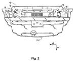
- FIG. 2 shows the latching device (10) of the computing unit of Figure 1 in greater detail in accordance with a preferred embodiment of the invention.
- the display portion of cover 25 has been removed in order to more clearly illustrate the operation of latching device 10 within the environment of cover 25'.
- the movement of latching device 10 in the +y direction causes shafts 17, coupled to latching device 10, to rotate hooks 15 about pivots 19.
- the hooks 15 are pulled inward along the "x" axis the hooks are brought out of contact with a receptacle, such as receptacle 20 of Figure 1.
- cover 25 (of Figure 1) can be opened.
- a notch can replace receptacle 20 and hooks 15 can be representative of any other type of retaining element.
- FIG 3 shows a more detailed view of the latching device of Figures 1 and 2, showing the grip surrounded by a receiver in accordance with a preferred embodiment of the invention.
- a receiver 35 substantially surrounds grip 30.
- grip 30 is formed using a pliant material such as a soft elastomeric plastic material such as silicone rubber.
- a soft elastomeric material is preferred, nothing prevents the use of a less soft material in particular applications.
- a substantially pliant material is used in this example in order to provide a soft surface that enables the user's finger or thumb to easily manipulate grip 30 and move the grip and receiver combination in a "+y" direction.
- grip 30 can be constructed using a more rigid material, using other elastomeric materials, such as urethane. However, regardless of the material chosen, it is preferable that the selected material be more pliant than the surrounding structure, such as receiver 35 for the example of Figure 3.
- ridge 45 runs substantially perpendicular to the "+y" direction. Ridge 45, located within depression 47, provides increased traction to the user's finger or thumb, thereby minimizing the force which the user need apply to grip 30 in order to manipulate the combination of grip 30 within receiver 35. Additional ridges, running in a direction that is parallel to ridge 45 can be used to further increase the traction of grip 30. Further, in order to permit the user's finger or thumb to fit securely within depression 47 of grip 30, periphery 40 of the grip rises to a height commensurate with the height of receiver 35.
- FIG 4 is an illustration of the grip of Figure 3 in accordance with a preferred embodiment of the invention.
- first tab 50 and second tab 60 enable grip 30 to be inserted into a receiver, such as receiver 35 of Figure 3.
- grip 30 is preferably inserted into a suitable receiver by appropriately compressing the grip in the "+y" dimension to insert the grip into the receiver.
- the use of first and second tabs 50 and 60 provides a means of inserting grip 30 into the receiver without requiring the use of an adhesive.
- Grip 30 desirably communicates forces exerted by the user to receiver 35.
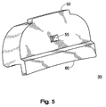
- Figure 5 is rear view of the grip of Figure 4 in accordance with a preferred embodiment of the invention.
- Figure 5 shows first and second tabs 50 and 60 as well as indent 55.
- Indent 55 provides a cavity that is suitable for accommodating a protrusion originating from receiver 35, thereby further restricting the movement of grip 30 within receiver 35 and allowing the grip to move in concert with the receiver.
- Figure 6 is a view of the receiver of Figure 3 in accordance with a preferred embodiment of the invention.
- first end portion 90 accepts first tab 50 of grip 30 of Figure 4.
- second end portion 100 opposite first end portion 90, accepts second tab 60 the grip.
- protrusion 105 is shown near the center, at an area between first and second end portions 90 and 100, respectively.
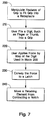
- Figure 7 is a flow diagram of a method performed by a grip, latching device, and a receiver in accordance with a preferred embodiment of the invention.
- the apparatus of Figure 1 is suitable for performing the method.
- features of the grip such as first and second tabs, are manipulated to fit the grip into a receptacle.
- a user fits a digit, such as finger or thumb, into a grip.
- the grip used in block 2 10 conforms to the shape of the digit.
- the method continues a block 220, in which the user applies force by way of the digit used in block 210.
- the force applied in block 220 is preferably along a direction that is substantially tangential to a surface of the grip.
- Block 230 conveys the force to a latch.
- Block 230 can further include conveying force to a receiver that, in turn, applies the force to a pivot that functions to actuate the latch.
- the latch moves a retaining element from contacting a notch, thereby releasing the cover of the electronic or computer unit.
Landscapes
- Engineering & Computer Science (AREA)
- Computer Hardware Design (AREA)
- Theoretical Computer Science (AREA)
- Physics & Mathematics (AREA)
- Human Computer Interaction (AREA)
- General Engineering & Computer Science (AREA)
- General Physics & Mathematics (AREA)
- Mathematical Physics (AREA)
- Casings For Electric Apparatus (AREA)
Abstract
A grip (30) is used to communicate force between a digit, such as a user's
finger or thumb, to a receiver (35). The grip (30) includes a first tab (50) that inserts
into a first end portion (90) of the receiver (35). The grip (30) further includes a
second tab (60) that inserts into a second end portion (100) of the receiver (35). The
second end (100) portion may be substantially opposite the first end portion (100).
Further, the grip (30) includes a depression that is formed into an area between the
first and second portions (90, 100) wherein the depression (47) is formed to accord
with the user's digit.
Description
- The invention relates generally to the field of latching devices and, more particularly, to devices used to latch a cover to a receptacle.
- In a portable computing unit, a latch is often used to secure the cover of the computing unit to another portion of the unit. Generally, the design of the latch is optimized to provide secure fastening of the cover to a receptacle located at another location on the computing unit while requiring only minimal effort to latch and unlatch the cover from the unit. Thus, a favorable latch design represents a balance between secure fastening and ergonomic design that assists in the unlatching and lifting of the cover.
- When a user begins a session using a portable computing unit, the user's first experience with the unit can be the unlatching of the cover from the computing unit. Thus, the design of the latching and unlatching mechanism can be an important aspect of the overall user experience. If this first experience of the user interacting with the latch is marginal, the entire experience of using the portable computing unit can be tainted. Therefore, it is desirable for the latch to securely fasten to the lid to the body of the computing unit while allowing the user to easily and effortlessly open the cover of the computing unit.
- The invention is pointed out with particularity in the appended claims. However, at least some important aspects of the invention are summarized in this section.
- In one aspect of the invention, a latching device for securing a cover to a receptacle is disclosed. The latching device includes a grip that is shaped to generally accord with the shape of either a user's finger or thumb. The latching device also includes a receiver attached to a cover, for retaining the grip and communicating force from the user's finger or thumb to a pivot. A hook is coupled to the pivot that latches the cover to a receptacle.
- In another aspect of the invention, a grip that communicates force between a user's digit, such as a finger or thumb, to a receiver is disclosed. The grip includes a first tab that inserts into a first end portion of the receiver. A second tab is included which inserts into a second end portion of the receiver, in which the second end portion of the receiver is substantially opposite the first end portion. A depression is formed into an area between the first and second end portions, with the depression being formed to accord with the digits.
- The invention is pointed out with particularity in the appended claims. However, a more complete understanding of the invention may be gained by reading the description herein, in conjunction with the figures, in which like reference numerals refer to like elements throughout the figures, and:
- Figure 1 shows an exemplary computing unit that includes a grip, latching device, and receptacle that operate in accordance with a preferred embodiment of the invention;
- Figure 2 shows the latching device of the computing unit of Figure 1 in greater detail in accordance with a preferred embodiment of the invention;
- Figure 3 shows a more detailed view of the latching device of Figures 1 and 2, showing the grip surrounded by a receiver in accordance with a preferred embodiment of the invention;
- Figure 4 is an illustration of the grip of Figure 3 in accordance with a preferred embodiment of the invention;
- Figure 5 is rear view of the grip of Figure 4 in accordance with a preferred embodiment of the invention;
- Figure 6 is a view of the receiver of Figure 3 in accordance with a preferred embodiment of the invention; and
- Figure 7 is a flow diagram of a method performed by a grip, latching device, and a receiver in accordance with a preferred embodiment of the invention,
-
- Figure 1 shows an exemplary computing unit that includes a grip, latching device, and receptacle that operates in accordance with a preferred embodiment of the invention. In Figure 1,
computing unit 5 includeslatching device 10 coupled tohooks 15, which insert intoreceptacle 20 whenfirst surface 26 is brought into contact withsecond surface 27. Preferably,hinges 80 enablecover 25, coupled tofirst surface 26, to rotate between a closed position and an open position shown in Figure 1. Preferably,cover 25 includes a display withinfirst surface 26 for displaying information to the user. It should be pointed out that although the exemplary embodiment of Figure 1 resembles a portable laptop computing unit, nothing prevents the use of the inventive principles in a variety of other applications, such as handheld computing units, handheld entertainment units, and other systems in which a cover, such ascover 25, is hingedly coupled to a second portion of the unit, such assecond surface 27. Further, a more detailed view of the grip, latching device, and receptacle are provided in subsequent figures herein. - Desirably, a user of the computing unit (5) of Figure 1 operates the computing unit in the open position. This position is enabled by way of the user a placing at least one digit, such as a thumb or finger, into contact with
latching device 10 and sliding the device appropriately in order to actuatehooks 15. Whenhooks 15 are actuated, they are moved out of contact withreceptacle 20, thereby enabling the rotation ofcover 25 abouthinges 80 to the open position shown. - Figure 2 shows the latching device (10) of the computing unit of Figure 1 in greater detail in accordance with a preferred embodiment of the invention. In Figure 2, the display portion of
cover 25 has been removed in order to more clearly illustrate the operation oflatching device 10 within the environment of cover 25'. According to Figure 2, the movement oflatching device 10 in the +y direction causesshafts 17, coupled tolatching device 10, to rotatehooks 15 aboutpivots 19. Ashooks 15 are pulled inward along the "x" axis the hooks are brought out of contact with a receptacle, such asreceptacle 20 of Figure 1. Whenhooks 15 are brought out of contact withreceptacle 20, cover 25 (of Figure 1) can be opened. In alternate embodiments, a notch can replacereceptacle 20 andhooks 15 can be representative of any other type of retaining element. - Figure 3 shows a more detailed view of the latching device of Figures 1 and 2, showing the grip surrounded by a receiver in accordance with a preferred embodiment of the invention. In Figure 3, a
receiver 35 substantially surroundsgrip 30. Preferably,grip 30 is formed using a pliant material such as a soft elastomeric plastic material such as silicone rubber. Although the use of a soft elastomeric material is preferred, nothing prevents the use of a less soft material in particular applications. However, a substantially pliant material is used in this example in order to provide a soft surface that enables the user's finger or thumb to easily manipulategrip 30 and move the grip and receiver combination in a "+y" direction. - As previously mentioned, nothing prevents the use of less pliant materials in the construction of
grip 30. Thus,grip 30 can be constructed using a more rigid material, using other elastomeric materials, such as urethane. However, regardless of the material chosen, it is preferable that the selected material be more pliant than the surrounding structure, such asreceiver 35 for the example of Figure 3. - As shown in Figure 3,
ridge 45 runs substantially perpendicular to the "+y" direction.Ridge 45, located withindepression 47, provides increased traction to the user's finger or thumb, thereby minimizing the force which the user need apply togrip 30 in order to manipulate the combination ofgrip 30 withinreceiver 35. Additional ridges, running in a direction that is parallel toridge 45 can be used to further increase the traction ofgrip 30. Further, in order to permit the user's finger or thumb to fit securely withindepression 47 ofgrip 30,periphery 40 of the grip rises to a height commensurate with the height ofreceiver 35. - Figure 4 is an illustration of the grip of Figure 3 in accordance with a preferred embodiment of the invention. In Figure 4,
first tab 50 andsecond tab 60 enablegrip 30 to be inserted into a receiver, such asreceiver 35 of Figure 3. Thus,grip 30 is preferably inserted into a suitable receiver by appropriately compressing the grip in the "+y" dimension to insert the grip into the receiver. The use of first andsecond tabs grip 30 into the receiver without requiring the use of an adhesive.Grip 30 desirably communicates forces exerted by the user toreceiver 35. - In view of the embodiments of Figures 2-4, those skilled in the art can envision alternate embodiments in which the pliant character of
grip 30 is exploited in order to fit grip 3 0 into place within receiver 3 5. - Figure 5 is rear view of the grip of Figure 4 in accordance with a preferred embodiment of the invention. Figure 5 shows first and
second tabs indent 55.Indent 55 provides a cavity that is suitable for accommodating a protrusion originating fromreceiver 35, thereby further restricting the movement ofgrip 30 withinreceiver 35 and allowing the grip to move in concert with the receiver. - Figure 6 is a view of the receiver of Figure 3 in accordance with a preferred embodiment of the invention. In Figure 6,
first end portion 90 acceptsfirst tab 50 ofgrip 30 of Figure 4. In a similar manner,second end portion 100, oppositefirst end portion 90, acceptssecond tab 60 the grip. Further,protrusion 105 is shown near the center, at an area between first andsecond end portions - Figure 7 is a flow diagram of a method performed by a grip, latching device, and a receiver in accordance with a preferred embodiment of the invention. The apparatus of Figure 1 is suitable for performing the method. At
block 200, features of the grip, such as first and second tabs, are manipulated to fit the grip into a receptacle. At block 2 10, a user fits a digit, such as finger or thumb, into a grip. Desirably, the grip used in block 2 10 conforms to the shape of the digit. The method continues ablock 220, in which the user applies force by way of the digit used inblock 210. The force applied inblock 220 is preferably along a direction that is substantially tangential to a surface of the grip. Atblock 230, the grip conveys the force to a latch. Block 230 can further include conveying force to a receiver that, in turn, applies the force to a pivot that functions to actuate the latch. Inblock 240 the latch moves a retaining element from contacting a notch, thereby releasing the cover of the electronic or computer unit. - The foregoing description of the specific embodiments will so fully reveal the general nature of the invention that others can, by applying current knowledge, readily modify and/or adapt for various applications such specific embodiments without departing from the generic concept, and therefore such adaptations and modifications should and are intended to be comprehended within the meaning and range of equivalents of the disclosed embodiments.
- It should be understood that the phraseology or terminology employed herein is for the purpose of description and not of limitation. Accordingly, the invention is intended to embrace all such alternatives, modifications, equivalents and variations as fall within the spirit and broad scope of the appended claims.
Claims (10)
- A latching device (10) for securing a cover (25) to a receptacle (20), comprising:a grip (30) shaped to accord with the shape of one of a finger and a thumb;a receiver (35), attached to said cover (25), for retaining said grip (30) and communicating force from said one of said finger and said thumb to a pivot (19); anda hook (15), coupled to said pivot (19), for latching said cover (25) to said receptacle (20).
- The latching device (10) of claim 1 wherein said grip (30) is shaped to accord with the shape of a thumb.
- The latching device (10) of claim 1 wherein said grip (30) is constructed using a pliant material.
- The latching device (10) of claim 3 wherein said grip (30) is constructed using silicone rubber.
- The latching device (10) of claim 1 wherein said grip (30) includes at least one ridge (45) that runs substantially perpendicular to the direction of said force exerted by said one of said finger and said thumb.
- A grip (30) used to communicate a force between a digit and a receiver (35), comprising:a first tab (50) that inserts into a first end portion (90) of said receiver;a second tab (60) that inserts into a second end portion (100) of said receiver (35), said second end portion (100) being substantially opposite of said first end portion (90); anda depression (47) formed into an area between said first and second end portions (90, 100), said depression (47) being formed to accord with said digit.
- The grip of claim 6 wherein said depression (47) further includes at least one ridge (45) that runs perpendicular to the direction of said force.
- The grip of claim 6 wherein said grip (30) is constructed using an elastomeric material.
- The grip of claim 8 wherein the periphery of said depression (47) is of a height similar to that of said receiver (35).
- A portable computing unit (5) having first surface (23) hingedly coupled to, and occasionally becoming proximate with, a second surface (27) of said portable computing unit (5), said portable computing unit (5) comprising:a grip (30), coupled to said first surface (23), said grip (30) being shaped to agree with the shape of a user's thumb;a receiver (35), connected to said first surface (23), for retaining said grip (30) and communicating force from said user's thumb to a shaft (17); anda hook (15), coupled to said shaft (17), for occasionally latching said first surface (23) to said second surface (26).
Applications Claiming Priority (2)
| Application Number | Priority Date | Filing Date | Title |
|---|---|---|---|
| US848401 | 2001-05-03 | ||
| US09/848,401 US20020163204A1 (en) | 2001-05-03 | 2001-05-03 | Grip for latching a cover to a receptacle |
Publications (1)
| Publication Number | Publication Date |
|---|---|
| EP1256868A2 true EP1256868A2 (en) | 2002-11-13 |
Family
ID=25303157
Family Applications (1)
| Application Number | Title | Priority Date | Filing Date |
|---|---|---|---|
| EP20020252831 Withdrawn EP1256868A2 (en) | 2001-05-03 | 2002-04-23 | Grip for latching a cover to a receptacle |
Country Status (2)
| Country | Link |
|---|---|
| US (1) | US20020163204A1 (en) |
| EP (1) | EP1256868A2 (en) |
Cited By (2)
| Publication number | Priority date | Publication date | Assignee | Title |
|---|---|---|---|---|
| EP1452947A1 (en) * | 2003-02-24 | 2004-09-01 | Kabushiki Kaisha Toshiba | Electronic apparatus having a latch to hold two units in a closed position and to be operated for release |
| CN100356292C (en) * | 2005-02-04 | 2007-12-19 | 华硕电脑股份有限公司 | Fastening device |
Families Citing this family (3)
| Publication number | Priority date | Publication date | Assignee | Title |
|---|---|---|---|---|
| JP6061909B2 (en) * | 2014-11-06 | 2017-01-18 | 京セラドキュメントソリューションズ株式会社 | Exterior member mounting structure, image forming apparatus |
| USD936139S1 (en) * | 2018-02-28 | 2021-11-16 | Sato Holdings Kabushiki Kaisha | Thermal head for a printer |
| USD910746S1 (en) | 2018-08-09 | 2021-02-16 | Sato Holdings Kabushiki Kaisha | Thermal head for a printer |
-
2001
- 2001-05-03 US US09/848,401 patent/US20020163204A1/en not_active Abandoned
-
2002
- 2002-04-23 EP EP20020252831 patent/EP1256868A2/en not_active Withdrawn
Cited By (3)
| Publication number | Priority date | Publication date | Assignee | Title |
|---|---|---|---|---|
| EP1452947A1 (en) * | 2003-02-24 | 2004-09-01 | Kabushiki Kaisha Toshiba | Electronic apparatus having a latch to hold two units in a closed position and to be operated for release |
| US7274562B2 (en) | 2003-02-24 | 2007-09-25 | Kabushiki Kaisha Toshiba | Electronic apparatus having a latch to hold two units in a closed position and to be operated for release |
| CN100356292C (en) * | 2005-02-04 | 2007-12-19 | 华硕电脑股份有限公司 | Fastening device |
Also Published As
| Publication number | Publication date |
|---|---|
| US20020163204A1 (en) | 2002-11-07 |
Similar Documents
| Publication | Publication Date | Title |
|---|---|---|
| US5689824A (en) | Folding portable wireless apparatus capable of automatically opening upper and lower cases | |
| KR100204158B1 (en) | Computers With a Separate Keyboard and a Separate Keyboard | |
| US6819549B1 (en) | Hinged protective cover for portable electronic device | |
| US8405981B2 (en) | Holding device for information processing device | |
| US20030100338A1 (en) | Personal digital assistant cover with an integrated keypad | |
| EP0703523A1 (en) | Palm rest for a data processing apparatus keyboard | |
| EP1681837A1 (en) | Connector cover for mobile communication terminal and mobile communication terminal | |
| US20020159226A1 (en) | External keyboard for personal digital assistant | |
| KR20000029031A (en) | Handheld computer keyboard system | |
| EP1517219A3 (en) | Information processing apparatus having switch for inputting key data | |
| JPH10509263A (en) | Interacting display user interface computer and method | |
| CN101650598A (en) | Keyboard | |
| EP1256868A2 (en) | Grip for latching a cover to a receptacle | |
| EP1293879B1 (en) | A battery pack for an information processing apparatus and the information processing apparatus | |
| US6392876B1 (en) | Portable computer with storage compartment | |
| US20040118743A1 (en) | Stylus fixing structure for a portable computer | |
| US6690579B1 (en) | Door for computing apparatus | |
| JP2011013738A (en) | Portable electronic devices | |
| JPH10312232A (en) | Information processing device | |
| JPH0513286Y2 (en) | ||
| KR100526746B1 (en) | Flat board-shaped mouse and the notebook using the same | |
| JP2747265B2 (en) | Lock release structure of electronic device with protective lid | |
| JPH0744267A (en) | Information processing equipment | |
| JP3316734B2 (en) | Keyboard device | |
| JPS6380314A (en) | Electronic equipment |
Legal Events
| Date | Code | Title | Description |
|---|---|---|---|
| PUAI | Public reference made under article 153(3) epc to a published international application that has entered the european phase |
Free format text: ORIGINAL CODE: 0009012 |
|
| AK | Designated contracting states |
Kind code of ref document: A2 Designated state(s): AT BE CH CY DE DK ES FI FR GB GR IE IT LI LU MC NL PT SE TR |
|
| AX | Request for extension of the european patent |
Free format text: AL;LT;LV;MK;RO;SI |
|
| STAA | Information on the status of an ep patent application or granted ep patent |
Free format text: STATUS: THE APPLICATION IS DEEMED TO BE WITHDRAWN |
|
| 18D | Application deemed to be withdrawn |
Effective date: 20040503 |