EP1256499A2 - Vehicle behavior control apparatus - Google Patents
Vehicle behavior control apparatus Download PDFInfo
- Publication number
- EP1256499A2 EP1256499A2 EP02009149A EP02009149A EP1256499A2 EP 1256499 A2 EP1256499 A2 EP 1256499A2 EP 02009149 A EP02009149 A EP 02009149A EP 02009149 A EP02009149 A EP 02009149A EP 1256499 A2 EP1256499 A2 EP 1256499A2
- Authority
- EP
- European Patent Office
- Prior art keywords
- yaw rate
- target yaw
- friction coefficient
- control apparatus
- road friction
- Prior art date
- Legal status (The legal status is an assumption and is not a legal conclusion. Google has not performed a legal analysis and makes no representation as to the accuracy of the status listed.)
- Granted
Links
Images


Classifications
-
- B—PERFORMING OPERATIONS; TRANSPORTING
- B60—VEHICLES IN GENERAL
- B60W—CONJOINT CONTROL OF VEHICLE SUB-UNITS OF DIFFERENT TYPE OR DIFFERENT FUNCTION; CONTROL SYSTEMS SPECIALLY ADAPTED FOR HYBRID VEHICLES; ROAD VEHICLE DRIVE CONTROL SYSTEMS FOR PURPOSES NOT RELATED TO THE CONTROL OF A PARTICULAR SUB-UNIT
- B60W10/00—Conjoint control of vehicle sub-units of different type or different function
- B60W10/12—Conjoint control of vehicle sub-units of different type or different function including control of differentials
- B60W10/16—Axle differentials, e.g. for dividing torque between left and right wheels
-
- B—PERFORMING OPERATIONS; TRANSPORTING
- B60—VEHICLES IN GENERAL
- B60T—VEHICLE BRAKE CONTROL SYSTEMS OR PARTS THEREOF; BRAKE CONTROL SYSTEMS OR PARTS THEREOF, IN GENERAL; ARRANGEMENT OF BRAKING ELEMENTS ON VEHICLES IN GENERAL; PORTABLE DEVICES FOR PREVENTING UNWANTED MOVEMENT OF VEHICLES; VEHICLE MODIFICATIONS TO FACILITATE COOLING OF BRAKES
- B60T8/00—Arrangements for adjusting wheel-braking force to meet varying vehicular or ground-surface conditions, e.g. limiting or varying distribution of braking force
- B60T8/17—Using electrical or electronic regulation means to control braking
- B60T8/172—Determining control parameters used in the regulation, e.g. by calculations involving measured or detected parameters
-
- B—PERFORMING OPERATIONS; TRANSPORTING
- B60—VEHICLES IN GENERAL
- B60T—VEHICLE BRAKE CONTROL SYSTEMS OR PARTS THEREOF; BRAKE CONTROL SYSTEMS OR PARTS THEREOF, IN GENERAL; ARRANGEMENT OF BRAKING ELEMENTS ON VEHICLES IN GENERAL; PORTABLE DEVICES FOR PREVENTING UNWANTED MOVEMENT OF VEHICLES; VEHICLE MODIFICATIONS TO FACILITATE COOLING OF BRAKES
- B60T8/00—Arrangements for adjusting wheel-braking force to meet varying vehicular or ground-surface conditions, e.g. limiting or varying distribution of braking force
- B60T8/17—Using electrical or electronic regulation means to control braking
- B60T8/1755—Brake regulation specially adapted to control the stability of the vehicle, e.g. taking into account yaw rate or transverse acceleration in a curve
-
- B—PERFORMING OPERATIONS; TRANSPORTING
- B60—VEHICLES IN GENERAL
- B60W—CONJOINT CONTROL OF VEHICLE SUB-UNITS OF DIFFERENT TYPE OR DIFFERENT FUNCTION; CONTROL SYSTEMS SPECIALLY ADAPTED FOR HYBRID VEHICLES; ROAD VEHICLE DRIVE CONTROL SYSTEMS FOR PURPOSES NOT RELATED TO THE CONTROL OF A PARTICULAR SUB-UNIT
- B60W10/00—Conjoint control of vehicle sub-units of different type or different function
- B60W10/12—Conjoint control of vehicle sub-units of different type or different function including control of differentials
- B60W10/14—Central differentials for dividing torque between front and rear axles
-
- B—PERFORMING OPERATIONS; TRANSPORTING
- B60—VEHICLES IN GENERAL
- B60W—CONJOINT CONTROL OF VEHICLE SUB-UNITS OF DIFFERENT TYPE OR DIFFERENT FUNCTION; CONTROL SYSTEMS SPECIALLY ADAPTED FOR HYBRID VEHICLES; ROAD VEHICLE DRIVE CONTROL SYSTEMS FOR PURPOSES NOT RELATED TO THE CONTROL OF A PARTICULAR SUB-UNIT
- B60W30/00—Purposes of road vehicle drive control systems not related to the control of a particular sub-unit, e.g. of systems using conjoint control of vehicle sub-units
- B60W30/02—Control of vehicle driving stability
-
- B—PERFORMING OPERATIONS; TRANSPORTING
- B60—VEHICLES IN GENERAL
- B60W—CONJOINT CONTROL OF VEHICLE SUB-UNITS OF DIFFERENT TYPE OR DIFFERENT FUNCTION; CONTROL SYSTEMS SPECIALLY ADAPTED FOR HYBRID VEHICLES; ROAD VEHICLE DRIVE CONTROL SYSTEMS FOR PURPOSES NOT RELATED TO THE CONTROL OF A PARTICULAR SUB-UNIT
- B60W40/00—Estimation or calculation of non-directly measurable driving parameters for road vehicle drive control systems not related to the control of a particular sub unit, e.g. by using mathematical models
- B60W40/02—Estimation or calculation of non-directly measurable driving parameters for road vehicle drive control systems not related to the control of a particular sub unit, e.g. by using mathematical models related to ambient conditions
- B60W40/06—Road conditions
- B60W40/064—Degree of grip
-
- B—PERFORMING OPERATIONS; TRANSPORTING
- B60—VEHICLES IN GENERAL
- B60W—CONJOINT CONTROL OF VEHICLE SUB-UNITS OF DIFFERENT TYPE OR DIFFERENT FUNCTION; CONTROL SYSTEMS SPECIALLY ADAPTED FOR HYBRID VEHICLES; ROAD VEHICLE DRIVE CONTROL SYSTEMS FOR PURPOSES NOT RELATED TO THE CONTROL OF A PARTICULAR SUB-UNIT
- B60W40/00—Estimation or calculation of non-directly measurable driving parameters for road vehicle drive control systems not related to the control of a particular sub unit, e.g. by using mathematical models
- B60W40/02—Estimation or calculation of non-directly measurable driving parameters for road vehicle drive control systems not related to the control of a particular sub unit, e.g. by using mathematical models related to ambient conditions
- B60W40/06—Road conditions
- B60W40/068—Road friction coefficient
-
- B—PERFORMING OPERATIONS; TRANSPORTING
- B60—VEHICLES IN GENERAL
- B60W—CONJOINT CONTROL OF VEHICLE SUB-UNITS OF DIFFERENT TYPE OR DIFFERENT FUNCTION; CONTROL SYSTEMS SPECIALLY ADAPTED FOR HYBRID VEHICLES; ROAD VEHICLE DRIVE CONTROL SYSTEMS FOR PURPOSES NOT RELATED TO THE CONTROL OF A PARTICULAR SUB-UNIT
- B60W40/00—Estimation or calculation of non-directly measurable driving parameters for road vehicle drive control systems not related to the control of a particular sub unit, e.g. by using mathematical models
- B60W40/10—Estimation or calculation of non-directly measurable driving parameters for road vehicle drive control systems not related to the control of a particular sub unit, e.g. by using mathematical models related to vehicle motion
- B60W40/114—Yaw movement
-
- B—PERFORMING OPERATIONS; TRANSPORTING
- B60—VEHICLES IN GENERAL
- B60W—CONJOINT CONTROL OF VEHICLE SUB-UNITS OF DIFFERENT TYPE OR DIFFERENT FUNCTION; CONTROL SYSTEMS SPECIALLY ADAPTED FOR HYBRID VEHICLES; ROAD VEHICLE DRIVE CONTROL SYSTEMS FOR PURPOSES NOT RELATED TO THE CONTROL OF A PARTICULAR SUB-UNIT
- B60W40/00—Estimation or calculation of non-directly measurable driving parameters for road vehicle drive control systems not related to the control of a particular sub unit, e.g. by using mathematical models
- B60W40/12—Estimation or calculation of non-directly measurable driving parameters for road vehicle drive control systems not related to the control of a particular sub unit, e.g. by using mathematical models related to parameters of the vehicle itself, e.g. tyre models
-
- B—PERFORMING OPERATIONS; TRANSPORTING
- B60—VEHICLES IN GENERAL
- B60G—VEHICLE SUSPENSION ARRANGEMENTS
- B60G2400/00—Indexing codes relating to detected, measured or calculated conditions or factors
- B60G2400/05—Attitude
- B60G2400/052—Angular rate
- B60G2400/0523—Yaw rate
-
- B—PERFORMING OPERATIONS; TRANSPORTING
- B60—VEHICLES IN GENERAL
- B60G—VEHICLE SUSPENSION ARRANGEMENTS
- B60G2400/00—Indexing codes relating to detected, measured or calculated conditions or factors
- B60G2400/10—Acceleration; Deceleration
- B60G2400/104—Acceleration; Deceleration lateral or transversal with regard to vehicle
-
- B—PERFORMING OPERATIONS; TRANSPORTING
- B60—VEHICLES IN GENERAL
- B60G—VEHICLE SUSPENSION ARRANGEMENTS
- B60G2400/00—Indexing codes relating to detected, measured or calculated conditions or factors
- B60G2400/10—Acceleration; Deceleration
- B60G2400/106—Acceleration; Deceleration longitudinal with regard to vehicle, e.g. braking
-
- B—PERFORMING OPERATIONS; TRANSPORTING
- B60—VEHICLES IN GENERAL
- B60G—VEHICLE SUSPENSION ARRANGEMENTS
- B60G2400/00—Indexing codes relating to detected, measured or calculated conditions or factors
- B60G2400/20—Speed
- B60G2400/208—Speed of wheel rotation
-
- B—PERFORMING OPERATIONS; TRANSPORTING
- B60—VEHICLES IN GENERAL
- B60G—VEHICLE SUSPENSION ARRANGEMENTS
- B60G2400/00—Indexing codes relating to detected, measured or calculated conditions or factors
- B60G2400/30—Propulsion unit conditions
-
- B—PERFORMING OPERATIONS; TRANSPORTING
- B60—VEHICLES IN GENERAL
- B60G—VEHICLE SUSPENSION ARRANGEMENTS
- B60G2400/00—Indexing codes relating to detected, measured or calculated conditions or factors
- B60G2400/30—Propulsion unit conditions
- B60G2400/39—Brake pedal position
-
- B—PERFORMING OPERATIONS; TRANSPORTING
- B60—VEHICLES IN GENERAL
- B60G—VEHICLE SUSPENSION ARRANGEMENTS
- B60G2400/00—Indexing codes relating to detected, measured or calculated conditions or factors
- B60G2400/40—Steering conditions
- B60G2400/41—Steering angle
- B60G2400/412—Steering angle of steering wheel or column
-
- B—PERFORMING OPERATIONS; TRANSPORTING
- B60—VEHICLES IN GENERAL
- B60G—VEHICLE SUSPENSION ARRANGEMENTS
- B60G2400/00—Indexing codes relating to detected, measured or calculated conditions or factors
- B60G2400/60—Load
- B60G2400/61—Load distribution
-
- B—PERFORMING OPERATIONS; TRANSPORTING
- B60—VEHICLES IN GENERAL
- B60G—VEHICLE SUSPENSION ARRANGEMENTS
- B60G2400/00—Indexing codes relating to detected, measured or calculated conditions or factors
- B60G2400/60—Load
- B60G2400/63—Location of the center of gravity
-
- B—PERFORMING OPERATIONS; TRANSPORTING
- B60—VEHICLES IN GENERAL
- B60G—VEHICLE SUSPENSION ARRANGEMENTS
- B60G2400/00—Indexing codes relating to detected, measured or calculated conditions or factors
- B60G2400/80—Exterior conditions
- B60G2400/82—Ground surface
- B60G2400/822—Road friction coefficient determination affecting wheel traction
-
- B—PERFORMING OPERATIONS; TRANSPORTING
- B60—VEHICLES IN GENERAL
- B60G—VEHICLE SUSPENSION ARRANGEMENTS
- B60G2600/00—Indexing codes relating to particular elements, systems or processes used on suspension systems or suspension control systems
- B60G2600/04—Means for informing, instructing or displaying
- B60G2600/044—Alarm means
-
- B—PERFORMING OPERATIONS; TRANSPORTING
- B60—VEHICLES IN GENERAL
- B60G—VEHICLE SUSPENSION ARRANGEMENTS
- B60G2800/00—Indexing codes relating to the type of movement or to the condition of the vehicle and to the end result to be achieved by the control action
- B60G2800/01—Attitude or posture control
- B60G2800/016—Yawing condition
-
- B—PERFORMING OPERATIONS; TRANSPORTING
- B60—VEHICLES IN GENERAL
- B60G—VEHICLE SUSPENSION ARRANGEMENTS
- B60G2800/00—Indexing codes relating to the type of movement or to the condition of the vehicle and to the end result to be achieved by the control action
- B60G2800/70—Estimating or calculating vehicle parameters or state variables
- B60G2800/702—Improving accuracy of a sensor signal
-
- B—PERFORMING OPERATIONS; TRANSPORTING
- B60—VEHICLES IN GENERAL
- B60G—VEHICLE SUSPENSION ARRANGEMENTS
- B60G2800/00—Indexing codes relating to the type of movement or to the condition of the vehicle and to the end result to be achieved by the control action
- B60G2800/70—Estimating or calculating vehicle parameters or state variables
- B60G2800/704—Estimating or calculating vehicle parameters or state variables predicting unorthodox driving conditions for safe or optimal driving
-
- B—PERFORMING OPERATIONS; TRANSPORTING
- B60—VEHICLES IN GENERAL
- B60G—VEHICLE SUSPENSION ARRANGEMENTS
- B60G2800/00—Indexing codes relating to the type of movement or to the condition of the vehicle and to the end result to be achieved by the control action
- B60G2800/90—System Controller type
- B60G2800/95—Automatic Traction or Slip Control [ATC]
- B60G2800/952—Electronic driving torque distribution
-
- B—PERFORMING OPERATIONS; TRANSPORTING
- B60—VEHICLES IN GENERAL
- B60G—VEHICLE SUSPENSION ARRANGEMENTS
- B60G2800/00—Indexing codes relating to the type of movement or to the condition of the vehicle and to the end result to be achieved by the control action
- B60G2800/90—System Controller type
- B60G2800/95—Automatic Traction or Slip Control [ATC]
- B60G2800/954—Four-wheel drive
-
- B—PERFORMING OPERATIONS; TRANSPORTING
- B60—VEHICLES IN GENERAL
- B60K—ARRANGEMENT OR MOUNTING OF PROPULSION UNITS OR OF TRANSMISSIONS IN VEHICLES; ARRANGEMENT OR MOUNTING OF PLURAL DIVERSE PRIME-MOVERS IN VEHICLES; AUXILIARY DRIVES FOR VEHICLES; INSTRUMENTATION OR DASHBOARDS FOR VEHICLES; ARRANGEMENTS IN CONNECTION WITH COOLING, AIR INTAKE, GAS EXHAUST OR FUEL SUPPLY OF PROPULSION UNITS IN VEHICLES
- B60K23/00—Arrangement or mounting of control devices for vehicle transmissions, or parts thereof, not otherwise provided for
- B60K23/04—Arrangement or mounting of control devices for vehicle transmissions, or parts thereof, not otherwise provided for for differential gearing
-
- B—PERFORMING OPERATIONS; TRANSPORTING
- B60—VEHICLES IN GENERAL
- B60T—VEHICLE BRAKE CONTROL SYSTEMS OR PARTS THEREOF; BRAKE CONTROL SYSTEMS OR PARTS THEREOF, IN GENERAL; ARRANGEMENT OF BRAKING ELEMENTS ON VEHICLES IN GENERAL; PORTABLE DEVICES FOR PREVENTING UNWANTED MOVEMENT OF VEHICLES; VEHICLE MODIFICATIONS TO FACILITATE COOLING OF BRAKES
- B60T2201/00—Particular use of vehicle brake systems; Special systems using also the brakes; Special software modules within the brake system controller
- B60T2201/14—Electronic locking-differential
-
- B—PERFORMING OPERATIONS; TRANSPORTING
- B60—VEHICLES IN GENERAL
- B60T—VEHICLE BRAKE CONTROL SYSTEMS OR PARTS THEREOF; BRAKE CONTROL SYSTEMS OR PARTS THEREOF, IN GENERAL; ARRANGEMENT OF BRAKING ELEMENTS ON VEHICLES IN GENERAL; PORTABLE DEVICES FOR PREVENTING UNWANTED MOVEMENT OF VEHICLES; VEHICLE MODIFICATIONS TO FACILITATE COOLING OF BRAKES
- B60T2250/00—Monitoring, detecting, estimating vehicle conditions
- B60T2250/02—Vehicle mass
-
- B—PERFORMING OPERATIONS; TRANSPORTING
- B60—VEHICLES IN GENERAL
- B60W—CONJOINT CONTROL OF VEHICLE SUB-UNITS OF DIFFERENT TYPE OR DIFFERENT FUNCTION; CONTROL SYSTEMS SPECIALLY ADAPTED FOR HYBRID VEHICLES; ROAD VEHICLE DRIVE CONTROL SYSTEMS FOR PURPOSES NOT RELATED TO THE CONTROL OF A PARTICULAR SUB-UNIT
- B60W2510/00—Input parameters relating to a particular sub-units
- B60W2510/20—Steering systems
-
- B—PERFORMING OPERATIONS; TRANSPORTING
- B60—VEHICLES IN GENERAL
- B60W—CONJOINT CONTROL OF VEHICLE SUB-UNITS OF DIFFERENT TYPE OR DIFFERENT FUNCTION; CONTROL SYSTEMS SPECIALLY ADAPTED FOR HYBRID VEHICLES; ROAD VEHICLE DRIVE CONTROL SYSTEMS FOR PURPOSES NOT RELATED TO THE CONTROL OF A PARTICULAR SUB-UNIT
- B60W2520/00—Input parameters relating to overall vehicle dynamics
- B60W2520/10—Longitudinal speed
- B60W2520/105—Longitudinal acceleration
-
- B—PERFORMING OPERATIONS; TRANSPORTING
- B60—VEHICLES IN GENERAL
- B60W—CONJOINT CONTROL OF VEHICLE SUB-UNITS OF DIFFERENT TYPE OR DIFFERENT FUNCTION; CONTROL SYSTEMS SPECIALLY ADAPTED FOR HYBRID VEHICLES; ROAD VEHICLE DRIVE CONTROL SYSTEMS FOR PURPOSES NOT RELATED TO THE CONTROL OF A PARTICULAR SUB-UNIT
- B60W2520/00—Input parameters relating to overall vehicle dynamics
- B60W2520/12—Lateral speed
- B60W2520/125—Lateral acceleration
-
- B—PERFORMING OPERATIONS; TRANSPORTING
- B60—VEHICLES IN GENERAL
- B60W—CONJOINT CONTROL OF VEHICLE SUB-UNITS OF DIFFERENT TYPE OR DIFFERENT FUNCTION; CONTROL SYSTEMS SPECIALLY ADAPTED FOR HYBRID VEHICLES; ROAD VEHICLE DRIVE CONTROL SYSTEMS FOR PURPOSES NOT RELATED TO THE CONTROL OF A PARTICULAR SUB-UNIT
- B60W2530/00—Input parameters relating to vehicle conditions or values, not covered by groups B60W2510/00 or B60W2520/00
- B60W2530/10—Weight
-
- B—PERFORMING OPERATIONS; TRANSPORTING
- B60—VEHICLES IN GENERAL
- B60W—CONJOINT CONTROL OF VEHICLE SUB-UNITS OF DIFFERENT TYPE OR DIFFERENT FUNCTION; CONTROL SYSTEMS SPECIALLY ADAPTED FOR HYBRID VEHICLES; ROAD VEHICLE DRIVE CONTROL SYSTEMS FOR PURPOSES NOT RELATED TO THE CONTROL OF A PARTICULAR SUB-UNIT
- B60W2540/00—Input parameters relating to occupants
- B60W2540/18—Steering angle
-
- B—PERFORMING OPERATIONS; TRANSPORTING
- B60—VEHICLES IN GENERAL
- B60W—CONJOINT CONTROL OF VEHICLE SUB-UNITS OF DIFFERENT TYPE OR DIFFERENT FUNCTION; CONTROL SYSTEMS SPECIALLY ADAPTED FOR HYBRID VEHICLES; ROAD VEHICLE DRIVE CONTROL SYSTEMS FOR PURPOSES NOT RELATED TO THE CONTROL OF A PARTICULAR SUB-UNIT
- B60W2552/00—Input parameters relating to infrastructure
- B60W2552/40—Coefficient of friction
-
- B—PERFORMING OPERATIONS; TRANSPORTING
- B60—VEHICLES IN GENERAL
- B60W—CONJOINT CONTROL OF VEHICLE SUB-UNITS OF DIFFERENT TYPE OR DIFFERENT FUNCTION; CONTROL SYSTEMS SPECIALLY ADAPTED FOR HYBRID VEHICLES; ROAD VEHICLE DRIVE CONTROL SYSTEMS FOR PURPOSES NOT RELATED TO THE CONTROL OF A PARTICULAR SUB-UNIT
- B60W2710/00—Output or target parameters relating to a particular sub-units
- B60W2710/12—Differentials
-
- B—PERFORMING OPERATIONS; TRANSPORTING
- B60—VEHICLES IN GENERAL
- B60W—CONJOINT CONTROL OF VEHICLE SUB-UNITS OF DIFFERENT TYPE OR DIFFERENT FUNCTION; CONTROL SYSTEMS SPECIALLY ADAPTED FOR HYBRID VEHICLES; ROAD VEHICLE DRIVE CONTROL SYSTEMS FOR PURPOSES NOT RELATED TO THE CONTROL OF A PARTICULAR SUB-UNIT
- B60W2720/00—Output or target parameters relating to overall vehicle dynamics
- B60W2720/14—Yaw
Definitions
- the present invention relates to a vehicle behavior control apparatus capable of calculating accurate target yaw rates used for various vehicle behavior control means.
- vehicle behavior control means such as a limited differential control, a driving force distribution control and the like have been applied to actual vehicles in market.
- control variables are calculated based on target yaw rates established according to vehicle motion conditions.
- a target yaw rate is established to a yaw rate exceeding the limit of yaw rate under which a vehicle can travel safely on a road surface with low friction coefficient and as a result the yaw rate conversely strengthens a tendency of spin of the vehicle.
- a front and rear wheels driving force distribution control of a four wheel drive vehicle when a yaw rate actually detected (actual yaw rate) is smaller than a target yaw rate, it is necessary to correct a driving force distribution of rear wheels in an increasing direction in order to enhance a turning ability. Therefore, in case where the same target yaw rate as that on a road surface with high friction coefficient has been established during traveling on a road surface with low friction coefficient, the front and rear wheel driving force distribution control tries to realize a target yaw rate exceeding a yaw rate under which a vehicle can travels in a stable manner. As a result, the driving force of rear wheels increases excessively, this leading to a spoilage of the traveling stability of the vehicle.
- low friction coefficient road a road surface with low friction coefficient
- Japanese Patent Application Laid-open No. Toku-Kai-Hei 5-278489 discloses a technique in which the target yaw rate is corrected in a smaller direction, as detecting values of friction coefficients of road surfaces decrease.
- Japanese Patent Application Laid-open No. Toku-Kai-Hei 6-72169 discloses a technology in which a dynamic characteristic of the vehicle with respect to steering operation is enhanced by establishing a steering responsibility of the vehicle, specifically, a first order lag time constant of yaw response of the vehicle with respect to steering operation according to vehicle speeds.
- the former prior art Toku-Kai-Hei 5-278489
- a road friction coefficient a friction coefficient on road surface
- the prior art has a restriction in detectable vehicle traveling conditions and also a problem of difficulty in optimization of target yaw rates.
- the latter prior art, Toku-Kai-Hei 6-72169 has an inadquate optimization of target yaw rate because the steering responsibility of the vehicle varies according to not only the vehicle speed but also the steering velocity.
- the front wheel steering angle calculating means includes a steering gear ratio varying means capable of varying a steering gear ratio according to a steering wheel rotation angle .
- the target yaw rate establishing means calculates the target yaw rate based on a steering gear ratio established by the steering gear ratio varying means.
- the target yaw rate establishing means includes a road friction coefficient estimating means for estimating a road friction coefficient.
- the target yaw rate establishing means calculates the target yaw rate by estimating a lag of target yaw rate with respect to steering according to the estimated road friction coefficient.
- the target yaw rate establishing means includes a warning means for warning the road friction coefficient and calculates the target yaw rate by estimating a lag of target yaw rate with respect to steering according to the estimated road friction coefficient and warns the estimated road friction coefficient by the warning means.
- the target yaw rate establishing means has a reference yaw rate calculating means for calculating a reference yaw rate which is a target yaw rate calculated by estimating a lag of yaw rate with respect to steering and the reference yaw rate is corrected by the reference yaw rate multiplied by a target yaw rate correction factor to obtain a final target yaw rate.
- the target yaw rate establishing means includes a road friction coefficient estimating means for estimating a road friction coefficient and calculates the target yaw rate by estimating a lag of target yaw rate with respect to steering according to the estimated road friction coefficient.
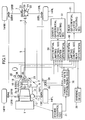
- the vehicle exemplified according to the first embodiment is a four wheel drive vehicle having a compound planetary gear type center differential and an automatic transmission.
- reference numeral 1 denotes an engine arranged at the front part of the vehicle.
- Driving force of the engine 1 is transmitted to a center differential 3 through an automatic transmission 2 disposed behind the engine 1 and a transmission output shaft 2a.
- Driving force on the rear wheel side inputs to a rear wheel final reduction gear unit 7 through a rear drive shaft 4, a propeller shaft 5 and a drive pinion 6 and driving force on the front wheel side inputs to a front wheel final reduction gear unit 11 through a transfer gear 8, transfer driven gear 9, front drive shaft 10.
- the automatic transmission 2, center differential 3 and front wheel final reduction gear unit 11 are integrally accommodated in a case 12.
- Driving force inputted to the rear wheel final reduction gear unit 7 is transmitted partly to a left rear wheel 14RL via a left rear wheel drive shaft 13RL and on the other hand transmitted partly to a right rear wheel 14RR via a right rear wheel drive shaft 13RR. Further, driving force inputted to the front wheel final reduction gear unit 11 is transmitted partly to a left front wheel 14FL via a left front wheel drive shaft 13FL and transmitted partly to a right front wheel 14FR via a left rear wheel drive shaft 13FR.
- a first sun gear 15 having a large diameter is mounted on the transmission output shaft 2a.
- the first sun gear 15 meshes with a first pinion 16 having a small diameter, thus a first gear train being constituted.
- a second sun gear 17 having a small diameter is mounted on the rear drive shaft 4 for transmitting power to the rear wheels.
- the second sun gear 17 meshes with a second pinion 18 having a large diameter, thus a second gear train being constituted.
- the first pinion 16 and second pinion 18 are integrally formed with a pinion member 19.
- a plurality of pinion members 19, for example three pinion members, are rotatably supported by a fixed shaft provided on a carrier 20. Further, the carrier 20 is connected at the front end thereof with the transfer drive gear 8 to output power to the front wheels.
- the carrier 20 is rotatably inserted from the front side by the transmission output shaft 2a and rotatably inserted from the rear side by the rear drive shaft 4.
- the first sun gear 15 and second sun gear 17 are accommodated in the vicinity of the central carrier 20.
- the first pinion 16 meshes with the first sun gear 15 and the second pinion 18 meshes with the second sun gear 17, respectively.
- the compound planetary gear type center differential 3 is provided with a differential function by appropriately establishing the number of teeth of those sun gears 15, 17 and pinions 16, 18.
- a desirable torque distribution including an unequal torque distribution weighted on rear wheels can be obtained by appropriately establishing working pitch diameters of the first and second pinions 16, 18 and the first and second sun gears 15, 17.
- the center differential 3 can leave a thrust load by applying helical gears to the first and second sun gears 15, 17 and the first and second pinions 16, 18 and giving a different helix angle to the first and second gear trains, respectively.
- the fixed shaft of the carrier 20 receives a resultant force of separating and tangential loads caused by the engagement of the pinions 16, 18. Accordingly, the friction torque generating at both ends of the pinion member 19 is affected by this thrust force and the resultant force of separating and tangential loads.
- friction torque between the pinion member 19 and carrier 20 works as a differential limiting torque proportional to the input torque. That is, the center differential 3 itself can have a differential limiting function.
- a transfer clutch 21 for varying the distribution of driving force between front and rear wheels between two output members of the center differential 3, that is, the carrier 20 and the rear drive shaft 4.
- the front and rear wheels torque distribution ratio of the center differential 3 can be varied within a range of 50:50 to 35: 65 for example by controlling the engagement force of the transfer clutch 21.
- the transfer clutch 21 is connected with a center differential clutch actuating section 51 constituted by a hydraulic circuit including a plurality of solenoid valves and is released or engaged by hydraulic pressure generated in the center differential clutch actuating section 51. Further, control signals to drive the center differential clutch driving section 51, output signals to be outputted to respective solenoid valves, are outputted from a differential limiting control section 50 for the center differential 3.
- the differential limiting control section 50 will be described hereinafter.
- the rear wheel final reduction gear unit 7 comprises a bevel gear type differential mechanism 22 and a rear differential clutch 23 including a hydraulic type multiple disc clutch for performing differential limiting motion between left and right wheels.
- the rear differential clutch 23 is provided between a differential case 25 secured to a ring gear 24 and the right rear wheel drive shaft 13RR and is connected with a rear differential clutch driving section 61 which is constituted by a hydraulic circuit including solenoid valves therein.
- the rear differential clutch 23 is released or engaged by a hydraulic pressure generated in the rear differential clutch actuating section 61. Further, control signals to drive the rear differential clutch actuating section 61, output signals to outputted to respective solenoid valves, are outputted from a differential limiting control section 60 for the rear differential.
- the differential limiting control section 60 will be described hereinafter.
- a target yaw rate ⁇ t and a road friction coefficient estimating value ⁇ e are used in the differential limiting control section 50. These target yaw rate ⁇ t and road friction coefficient estimating value ⁇ e are outputted from a target yaw rate establishing section 70 which will be described hereinafter.
- differential limiting control sections 50, 60 and the target yaw rate establishing section 70 input necessary control parameters from respective sensors and an engine control section as will be described hereinafter.
- Wheel speeds of respective wheels 14FL, 14FR, 14RL and 14RR are detected by wheel speed sensors 32FL, 32FR, 32RL and 32RR, respectively and an actually generating yaw rate ⁇ is detected from a yaw rate sensor 33. These values are inputted to the differential limiting control sections 50, 60 and target yaw rate establishing section 70.
- An accelerator pedal opening angle ⁇ ac is detected by an accelerator pedal opening angle sensor 34 and is inputted to the differential limiting control section 50 for the center differential and the differential limiting control section 60 for the rear differential.
- a warning lamp 39 lighting in red when a road friction coefficient ⁇ e is outputted from the target yaw rate establishing section 70 on an instrument panel of the vehicle .
- the warning lamp 39 lights in red.
- a picture for visually indicating a slippery road surface may light in red.
- a sound warning raising an alarm "you are on a slippery road" to a driver may be used.
- the target yaw rate establishing section 70 for outputting a target yaw rate ⁇ t and a road friction coefficient estimating value ⁇ e to the differential limiting control sections 50, 60 will be described.
- the target yaw rate establishing section 70 comprises a vehicle speed calculating section 70a, vehicle mass estimating section 70b, front and rear wheel mass distribution ratio calculating section 70c, front and rear axle mass estimating section 70d, front and rear axle to gravity center distance estimating section 70e, front and rear wheel equivalent cornering power estimating section 70f, stability factor reference value calculating section 70g, front wheel steering angle calculating section 70h, target yaw rate correction factor mean value calculating section 70i, stability factor calculating section 70j, steady state yaw rate gain calculating section 70k, reference yaw rate steady state value calculating section 701, yaw inertia radius calculating section 70m, road friction coefficient estimating section 70n, first order lag time constant calculating section 70o, reference yaw rate calculating section 70p, correction speed calculating section 70q, actual yaw rate follow-up first order lag cut-off frequency calculating section 70r, actual yaw rate follow-up first order lag time constant calculating section 70s
- the vehicle speed calculating section 70a inputs wheel speeds of respective wheels 14FL, 14FR, 14RL, 14RR from respective wheel speed sensors 32FL, 32FR, 32RL, 32RR.
- a vehicle speed V is calculated by averaging these wheel speeds and is outputted to the steady state yaw rate gain calculating section 70k, first order lag time constant calculating section 70o, correction speed calculating section 70q and minimum yaw rate calculating section 70v.
- the vehicle mass estimating section 70b inputs a total driving force Td from the engine control section 31, a longitudinal acceleration Gx from the longitudinal acceleration sensor 37, a brake fluid pressure Pb from the brake fluid pressure sensor 38, respectively and estimates a vehicle mass me according to the following formulas (1) or (2).
- me Kb ⁇ Pb/Gxb (on deceleration)
- me Kd ⁇ Td/Gxd (on accleration)
- Kb, Kd is a conversion factor
- Gxb, Gxd is a deceleration or acceleration when the vehicle is braked or driven.
- estimated vehicle mass me is outputted to the front and rear mass distribution ratio calculating section 70c, front and rear axle mass estimating section 70d, front and rear axle to gravity center distance estimating section 70e, stability factor reference value calculating section 70g, yaw inertia radius calculating section 70m and first order lag time constant calculating section 70o.
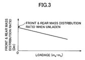
- the front and rear mass distribution ratio calculating section 70c inputs a vehicle mass me from the vehicle mass estimating section 70b and calculates a front and rear mass distribution ratio Dm by reference to such a table as shown in Fig. 3.
- the table of Fig. 3 indicates that the front and rear mass distribution ratio increases on the rear wheel side with an increase of loadage me - m0 (m0 is a vehicle mass when unladen) .
- front and rear mass distribution ratio Dm is inputted to the front and rear axle mass estimating section 70d.
- the front and rear axle mass estimating section 70d inputs a vehicle mass me and a front and rear mass distribution ratio Dm from the vehicle mass estimating section 70b and the front and rear mass distribution ratio calculating section 70c, respectively.
- a front axle mass mfe and rear axle mass mre are calculated.
- calculated front axle mass mfe and rear axle mass mre are outputted to the front and rear axle to gravity center distance estimating section 70e and front and rear wheel equivalent cornering power estimating section 70f.
- the front and rear axle to gravity center distance estimating section 70e inputs a vehicle mass me and a front axle mass mfe and rear axle mass mre from the vehicle mass estimating section 70b and the front and rear axle mass estimating section 70d, respectively.
- a front axle to gravity center distance Lfe and rear axle to gravity center distance Lre are calculated according to the following formulas (5) and (6), respectively.
- Lfe L ⁇ (mre/me)
- Lre L ⁇ (mfe/me) where L is wheel base.
- estimated front axle to gravity center distance Lfe and rear axle to gravity center distance Lre are outputted to the stability factor reference value calculating section 70g and first order lag time constant calculating section 70o, respectively.
- the front and rear wheel equivalent cornering power estimating section 70f inputs a front axle mass mfe and rear axle mass mre from the front and rear axle mass estimating section 70d and calculates a front wheel equivalent cornering power Kfe and rear wheel equivalent cornering power Kre in accordance with the following formulas (7) and (8).
- Kfe Kf0 ⁇ (mfe/mf0)
- Kre Kr0 ⁇ (mre/mr0) where Kf0 is a front wheel equivalent cornering power when unladen; Kr0 is a rear wheel equivalent cornering power in an unladen condition; mf0 is a front axle mass in an unladen condition; and mr0 is a rear axle mass in an unladen condition.
- Kfe Kf0 ⁇ (mfe/mf0)
- Kre Kr0 ⁇ (mre/mr0)
- Kf0 is a front wheel equivalent cornering power when unladen
- Kr0 is a rear wheel equivalent cornering power in an unladen condition
- the stability factor reference value calculating section 70g inputs a vehicle mass me, front axle to gravity center distance Lfe and rear axle to gravity center distance Lre, front wheel equivalent cornering power Kfe and rear wheel equivalent cornering power Kre from the vehicle mass estimating section 70b, front and rear axle to gravity center distance estimating section 70e and front and rear wheel equivalent cornering power estimating section 70f, respectively and calculates a stability factor reference value A0 according to the following formula (9).
- A0 -(me/(2 ⁇ L 2 ) ⁇ ((Lfe ⁇ Kfe-Lre ⁇ Kre)/(Kfe ⁇ Kre))
- the stability factor reference value A0 is outputted to the stability factor calculating section 70j.
- the aforesaid table is designed so that the steering gear ratio n is decreased to enhance a steering responsibility when the vehicle travels nearly straight and is increased to reduce the steering effort when the vehicle turns corners.
- the front wheel steering angle ⁇ f is calculated directly from the formula (10) by letting n be constant.
- the calculated front wheel steering angle ⁇ f is outputted to the target yaw rate correction factor mean value calculating section 70i and the reference yaw rate steady state value calculating section 701.
- the target yaw rate correction factor mean value calculating section 70i inputs a front wheel steering angle ⁇ f and target yaw rate correction factor C ⁇ m from the front wheel steering angle calculating section 70h and target yaw rate correction factor calculating section 70t, respectively and calculates a mean value C ⁇ mAL within a specified time of the target yaw rate correction factor C ⁇ m when turning to left (left steering) and a mean value C ⁇ mAR within a specified time of the target yaw rate correction factor C ⁇ m when turning to right (right steering) . Then, these mean values C ⁇ mAL and C ⁇ mAR are outputted to the stability factor calculating section 70j.
- the stability factor AL, AR thus calculated are outputted as a stability factor A to the steady state yaw rate gain calculating section 70k.
- the calculated reference yaw rate steady state value ⁇ ts is outputted to the reference yaw rate calculating section 70p.
- the yaw inertia radius calculating section 70m inputs a vehicle mass me from the vehicle mass estimating section 70b and calculates a yaw inertia radius Rk according to the following formula (15).
- the yaw inertia radius Rk is outputted to the first order lag time constant calculating section 70o.
- Rk (Iz/me) 1/2 where Iz is a yaw inertia moment.
- the road friction coefficient estimating section 70n inputs a target yaw rate correction factor C ⁇ m from the target yaw rate correction factor calculating section 70t and calculates a road friction coefficient estimating value ⁇ e in accordance with the following formula (16) and outputs this value to the first order lag time constant calculating section 70o, warning device 39, differential limiting control section 50 of the center differential and differential limiting control section 60 of the rear differential.
- ⁇ e 1 - C ⁇ m
- the first order lag time constant calculating section 70o inputs a vehicle speed V from the vehicle speed calculating section 70a, a vehicle mass me from the vehicle mass estimating section 70b, a front axle to gravity center distance Lfe and rear axle to gravity center distance Lre from the front and rear axle to gravity center distance estimating section 70e, a front wheel equivalent cornering power Kfe and rear wheel equivalent cornering power Kre from the front and rear wheel equivalent cornering power estimating section 70f, a yaw inertia radius Rk from the yaw inertia radius calculating section 70m and a road friction coefficient estimating value ⁇ e from the road friction coefficient estimating section 70n and calculates a first order lag time constant Tr which is used when the yaw rate has a dynamic characteristic according to the following formula (17).
- Tr(k) ((me ⁇ V(k))/(2 ⁇ (Kfe + Kre) ⁇ e(k-1))) ⁇ (Rk 2 /(Lfe ⁇ Lre) where (k) means a present value and (k-1) means a previous value.
- the first order lag time constant Tr (k) is outputted to the reference yaw rate calculating section 70p.
- the reference yaw rate calculating section 70p inputs a reference yaw rate steady state value ⁇ ts from the reference yaw rate steady state calculating section 701 and a first order lag time constant Tr(k) from the first order lag time constant calculating section 70o and calculates a reference yaw rate ⁇ t0 according to the following formula (18) and outputs the reference yaw rate ⁇ t0 to the actual yaw rate follow-up first order lag cut-off frequency calculating section 70r, target yaw rate correction factor calculating section 70t, target yaw rate calculating section 70u and target yaw rate limiting section 70w.
- ⁇ t0(k) ⁇ t0(k-1) + ( ⁇ ts(k) - ⁇ t0(k-1)) ⁇ ( ⁇ t/Tr(k)) where ⁇ t is calculation cycle time.
- the reference yaw rate ⁇ t0(k) is a target yaw rate as a basis of correction. As clearly understood from the formula (18), it is a target yaw rate having a dynamic characteristic including first order lag.
- the correction speed calculating section 70q inputs an actual yaw rate ⁇ from the yaw rate sensor 33, an actual lateral acceleration Gy from the lateral acceleration sensor 36, and a vehicle speed V from the vehicle speed calculating section 70a and calculates a factor Cy for reducing a correction speed of the increasing target yaw rate according to the following formula (19) and (20) and outputs the factor Cy to the actual yaw rate follow-up first order lag cut-off frequency calculating section.
- the actual acceleration Gy is corrected by deleting a gravitational acceleration component caused by roll. Accordingly, Gy' is dependent upon the specification of the lateral acceleration sensor 36.
- the factor Cy for reducing the correction speed of the increasing target yaw rate is established so as to be larger, as the difference between the lateral acceleration Gy ⁇ calculated from the actual yaw rate ⁇ and the corrected lateral acceleration Gy' obtained from the lateral acceleration sensor 36 increases.
- the following-up of target yaw rate to actual yaw rate is delayed by the correction of the target yaw rate correction factor C ⁇ m when the vehicle has a spin tendency. The correction will be described hereinafter.
- the actual yaw rate follow-up first order lag cut-off frequency calculating section 70r inputs the actual yaw rate ⁇ from the yaw rate sensor 33, the reference yaw rate ⁇ t0 from the reference yaw rate calculating section 70p, the factor Cy from the correction speed calculating section 70q and the target yaw rate ⁇ t from the target yaw rate calculating section 70u and calculates a first order lag cut-off frequency Fm which follows the actual yaw rate ⁇ according to formulas (21) and (22) expressed below:
- the actual yaw rate follow-up first order lag time constant calculating section 70s inputs the first order lag cut-off frequency Fm following the actual yaw rate ⁇ from the actual yaw rate follow-up first order lag cut-off frequency calculating section 70r and calculates a first order lag time constant Tm following the actual yaw rate ⁇ according to the following formula (23) and outputs the calculated Tm to the target yaw rate correction factor calculating section 70t.
- Tm 1/(2 ⁇ Fm)
- the target yaw rate correction factor calculating section 70t inputs the actual yaw rate ⁇ from the yaw rate sensor 33, the reference yaw rate ⁇ t0 from the reference yaw rate calculating section 70p, the first order lag time constant Tm following the actual yaw rate ⁇ and the target yaw rate ⁇ t from the target yaw rate calculating section 70u and calculates a target yaw rate correction factor C ⁇ m with first order lag with respect to the actual yaw rate ⁇ according to the following formula (24).
- C ⁇ mt(k) is a target value of a target yaw rate correction factor.
- target yaw rate correction factor C ⁇ m is outputted to the target yaw rate correction factor mean value calculating section 70i, road friction coefficient estimating section 70n and target yaw rate calculating section 70u.
- C ⁇ m ⁇ t0 acts as a correction quantity with respect to the reference yaw rate ⁇ t0.
- calculated target yaw rate ⁇ t is outputted to the actual yaw rate follow-up first order lag cut-off frequency calculating section 70r, target yaw rate correction factor calculating section 70t and target yaw rate limiting section 70w, respectively.
- a minimum yaw rate ⁇ min' introducing an intrinsic error ⁇ of the yaw rate sensor is calculated from the following formula (27) or (28):
- the target yaw rate limiting section 70w inputs the yaw rate ⁇ from the yaw rate sensor 33, the reference yaw rate ⁇ t0 from the reference yaw rate calculating section 70p, the target yaw rate ⁇ t from the target yaw rate calculating section 70u, and the corrected minimum yaw rate ⁇ min' from the minimum yaw rate calculating section 70v.
- the target yaw rate ⁇ t is limited according to the following formula (29) and at the same time a target yaw rate correction factor C ⁇ m is calculated according to the formula (30).
- the condition is:
- the target yaw rate ⁇ t is directly outputted from the target yaw rate calculating section 70u to the center differential differential limiting control 50 and rear differential differential limiting control 60.
- the target yaw rate correction factor C ⁇ m calculated according to the formula (30) is outputted to the target yaw rate correction factor calculating section 70t.
- the center differential differential limiting control section 50 will be described by reference to a functional block diagram of Fig. 4.
- the center differential differential limiting control section 50 comprises a vehicle speed calculating section 50a, an accelerator pedal opening angle and vehicle speed sensitive differential limiting force establishing section 50b, a road friction coefficient sensitive differential limiting force establishing section 50c, a center differential base differential limiting force calculating section 50d, a center differential differential limiting force correction quantity calculating section 50e and a center differential differential limiting force correcting section 50f.
- the vehicle speed calculating section 50a inputs wheel speeds of respective wheels 14FL, 14FR, 14RL and 14RR from wheel speed sensors 32FL, 32FR, 32RL and 32RR, as in the same manner as the vehicle speed calculating section 70a. These wheel speeds are averaged to calculate a vehicle speed V and the vehicle speed V is outputted to the accelerator valve opening angle and vehicle speed sensitive differential limiting force establishing section 50b.
- the accelerator pedal opening angle and vehicle speed sensitive differential limiting force establishing section 50b inputs an accelerator pedal opening angle ⁇ ac and the vehicle speed V from the vehicle speed calculating section 50a and establishes an accelerator pedal opening angle and vehicle speed sensitive differential limiting force TLSDCA by referring to predetermined look-up tables parameterizing the accelerator pedal opening angle ⁇ ac and vehicle speed V and outputs to the center differential base differential limiting force calculating section 50d.
- the look-up tables are established for each speed ratio, first gear to fourth gear and reverse. For example, as the accelerator pedal opening angle ⁇ ac is small, and as the vehicle speed V is high, the accelerator pedal opening angle and vehicle speed sensitive differential limiting force TLSDCA is established to a smaller value to enhance turning ability and fuel economy.
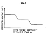
- the road friction coefficient sensitive differential limiting force establishing section 50c inputs the road friction coefficient estimating value ⁇ e from the target yaw rate establishing section 70 and establishes a road friction coefficient sensitive differential force TLSDC ⁇ by reference to a predetermined look-up table parameterizing the road friction coefficient estimating value ⁇ e and outputs to the center differential base differential limiting force calculating section 50d.
- This look-up table parameterizing the road friction coefficient estimating value ⁇ e has a characteristic as shown in Fig. 5. As the road friction coefficient ⁇ e becomes small, the roas friction coefficient sensitive differential limiting force TLSDC ⁇ is established to be larger and the power distribution on a road surface with low friction coefficient is designed to come close to an equal front and rear distribution ratio of 50:50 to enhance vehicle stability.
- the center differential base differential limiting force calculating section 50d inputs the accelerator pedal opening angle and vehicle speed sensitive differential limiting force TLSDCA from the accelerator pedal opening angle and vehicle speed sensitive differential limiting force establishing section 50b and the road friction coefficient sensitive differential limiting force TLSDC ⁇ from the road friction coefficient sensitive differential limiting force establishing section 50c and makes an addition of these to produce a center differential base differential limiting force TLSDCm accoding to the following formula (31) and outputs to the center differential differential limiting force correcting section 50f.
- TLSDCm TLSDCA + TLSDC ⁇
- the center differential differential limiting force correction quantity calculating section 50e inputs the actual yaw rate ⁇ and the target yaw rate ⁇ t from the target yaw rate establishing section 70 and calculates a center differential differential limiting force correction quantity TLSDCy according to the following formula (32) and outputs to the center differential differential limiting force correcting section 50f.
- TLSDCy ⁇ - ⁇ t ⁇ Gyc where Gyc is a correction gain.
- the center differential differential limiting force correction quantity TLSDCy is established to a larger value.
- the center differential differential limiting force correcting section 50f inputs the center differntial base differntial limiting force TLSDCm from the center differential differential limiting force calculating section 50d and the center differntial differntial limiting force correction quantity TLSDCy from the center differntial differential limiting force correction quantity calculating section 50e and makes an addition of these according to the following formula (33) to produce a center differntial differntial limiting force TLSDC and outputs to the center differential clutch activating section 51.
- TLSDC TLSDCm + TLSDCy
- the rear differential differential limiting control section 60 comprises a vehicle speed calculating section 60a, an accelerator pedal opening angle and vehicle speed sensitive differential limiting force establishing section 60b, a road friction coefficient sensitive differential limiting force establishing section 60c, a rear differential base differential limiting force calculating section 60d, a rear differential differential limiting force correction quantity calculating section 60e and a rear differential differential limiting force correcting section 60f.
- the vehicle speed calculating section 60a inputs wheel speeds of respective wheels 14FL, 14FR, 14RL and 14RR from wheel speed sensors 32FL, 32FR, 32RL and 32RR in the same manner as the vehicle speed calculating section 70a. These wheel speeds are averaged to calculate a vehicle speed V and the vehicle speed V is outputted to the accelerator valve opening angle and vehicle speed sensitive differential limiting force establishing section 60b.
- the accelerator pedal opening angle and vehicle speed sensitive differential limiting force establishing section 60b inputs an accelerator pedal opening angle ⁇ ac and the vehicle speed V from the vehicle speed calculating section 60a and establishes an accelerator pedal opening angle and vehicle speed sensitive differential limiting force TLSDRA by referring to look-up tables predetermined parameterizing the accelerator pedal opening angle ⁇ ac and vehicle speed V and outputs to the rear differential base differential limiting force calculating section 60d.
- the look-up tables are established for each speed ratio, first gear to fourth gear and reverse. For example, as the accelerator pedal opening angle ⁇ ac is small, and as the vehicle speed V is high, the accelerator pedal opening angle and vehicle speed sensitive differential limiting force TLSDRA is established to a smaller value.
- the road friction coefficient sensitive differential limiting force establishing section 60c inputs the road friction coefficient estimating value ⁇ e from the target yaw rate establishing section 70 and establishes a road friction coefficient sensitive differential force TLSDR ⁇ by reference to a predetermined look-up table parameterizing the road friction coefficient estimating value ⁇ e and outputs to the rear differential base differential limiting force calculating section 60d.
- This look-up table parameterizing the road friction coefficient estimating value ⁇ e is designed such that as the road friction coefficient ⁇ e becomes small, the road friction coefficient sensitive differential limiting force TLSDR ⁇ is established to a larger value to enhance vehicle stability.
- the rear differential base differential limiting force calculating section 60d inputs the accelerator pedal opening angle and vehicle speed sensitive differential limiting force TLSDRA from the accelerator pedal opening angle and vehicle speed sensitive differential limiting force establishing section 60b and the road friction coefficient sensitive differential limiting force TLSDR ⁇ from the road friction coefficient sensitive differential limiting force establishing section 60c and makes an addition of these to produce a rear differential base differential limiting force TLSDRm according to the following formula (34) and outputs to the rear differential differential limiting force correcting section 60f.
- TLSDRm TLSDRA + TLSDR ⁇
- the rear differential differential limiting force correcting section 60f inputs the rear differntial base differntial limiting force TLSDRm from the rear differential differential limiting force calculating section 60d and the rear differntial differntial limiting force correction quantity TLSDRy from the reare differntial differential limiting force correction quantity calculating section 60e and makes an addition of these according to the following formula (37) to produce a rear differntial differntial limiting force TLSDR and outputs to the rear differential clutch activating section 61.
- TLSDR TLSDRm + TLSDRy
- the program goes to S103 where the reference yaw rate ⁇ ts is calculated according to the formula (14).
- the program goes to S104 in which the reference yaw rate ⁇ t0 is calculated according to the formula (18).
- the program goes to S105 where the target yaw rate correction factor C ⁇ m is calculated according to the aforesaid formula (24). After this correction factor C ⁇ m is memorized, the counter is incremented by one.
- the program goes to S106 where the target yaw rate ⁇ t is calculated according to the formula (25).
- the condition on which the target yaw rate ⁇ t is limited (limiting condition by ⁇ min') is satisfied.
- the road friction coefficient estimating value ⁇ e is calculated by the aforesaid formula (16) and at S110 the target yaw rate ⁇ t is outputted to the center differential differential limiting control section 50 and rear differential differential limiting control section 60. Further, the road friction coefficient estimating value ⁇ e is outputted to the warning device 39, center differential differential limiting control section and rear differential differential limiting control section 60.
- the program goes to S111 where it is judged whether or not the target yaw rate correction factor C ⁇ m is memorized by a specified number of times. If it is not memorized specified times, the program leaves the routine and if it is memorized specified times, the program goes to S112.
- the stability factor when turning to left AL and stability factor when turning to right AR are corrected by the average value of the memorized target yaw rate correction factors C ⁇ m, respectively and the program goes to S113 where the memory counter is reset, leaving the routine.
- an accurate target yaw rate ⁇ t is calculated taking the vehicle mass me, front and rear mass distribution ratio Dm, front axle mass mfe, rear axle mass mre, front axle to gravity center distance Lfe, rear axle to gravity center distance Lre, front wheel cornering power Kfe, rear wheel cornering power Kre and actual front wheel steering angle ⁇ f into cosideration.
- a separate steady state yaw rate gain G ⁇ is established for the steering to left and the steering to right, respectively, the yaw rate gain G ⁇ can be adjusted by comparing the correction hysteresis of the target yaw rate on a steering to right with the one of the target yaw rate on a steering to left.
- an accurate target yaw rate ⁇ t can be calculated in consideration of different characteristics between when steering to right and when steering to left.
- an accurate reference yaw rate ⁇ t0 can be calculated by changing the lag time constant Tr of yaw rate response to steering based on the road friction coefficient estimating value ⁇ e.
- the target yaw rate ⁇ t is prevented from excessively glowing large by reducing or prohibiting the correction velocity of correcting the reference yaw rate ⁇ t0 by the target yaw rate correction factor C ⁇ m and as a result the target yaw rate ⁇ t can be optimized.
- the correction quantity of the target yaw rate ⁇ t is a ratio to the reference yaw rate ⁇ t0 and is memorized as the road friction coefficient estimating value ⁇ e, the change of yaw rate when a driver operates a steering wheel is separated from the change of yaw rate when the condition of road surfaces changes. As a result, a stable estimation of road surface conditions and a sensitive disturbance detection can be obtained.
- the target yaw rate ⁇ t with high precision enables an accurate power distribution between front and rear wheels.
- the target yaw rate ⁇ t with high precision enables an accurate power distribution between left and right wheels.
- a front and rear driving force distributing section 80 between the output shaft 2a of the transmission and the rear drive shaft 4.
- the front and rear driving force distributing section 80 can vary driving force distribution by changing the engagement force of a hydraulic multiple-disc clutch 81 according to the rotation difference between input and output shafts.
- the front and rear driving force distributing section 80 includes a plunger pump 83 for generating hydraulic pressure by longitudinally reciprocating a plunger 83a by a swash plate 82 provided at the rear end of the transmission output shaft 2a. Hydraulic pressure generated by the plunger pump 83 is varied by a control valve of a torque distribution clutch actuating section 85 provided on a hydraulic piping 84.
- Reference numeral 86 denotes a reservoir.
- the torque distribution clutch actuating section 85 is connected with a front and rear driving force distribution control section 90 for varying the engagement force of the hydraulic multiple-disc clutch 81.
- the front and rear driving force distribution control section 90 comprises a vehicle speed calculating section 90a, a base torque characteristic establishing section 90b, a torque characteristic correction quantity calculating section 90c and a base torque characteristic correcting section 90d.
- the vehicle speed calculating section 90a inputs wheel speeds of respective wheels 14FL, 14FR, 14RL and 14RR from wheel speed sensors 32FL, 32FR, 32RL and 32RR in the same manner as the vehicle speed calculating section 70a. These wheel speeds are averaged to calculate a vehicle speed V and the vehicle speed V is outputted to the base torque characteristic establishing section 90b.
- the base torque characteristic establishing section 90b expresses the engaging force of the hydraulic multiple-disc clutch 81 as a base torque characteristic value Kcm which is established to a constant value or to an increasing function versus to the vehicle speed V and outputs to the base torque characteristic correcting section 90d.
- the torque characteristic correction quantity Kcy is established to a larger value.
- the base torque characteristic correcting section 90d inputs the base torque characteristic value Kcm and the torque characteristic correction quantity Kcy from the torque characteristic correction quantity calculating section 90c and makes an addition of these to calculate a transmission torque Kc generating when the hydraulic multiple-disc clutch 81 is engaged according to the following formula (39) and outputs to the torque distribution clutch actuating section 85.
- Kc Kcm + Kcy
- the transmission torque Kc which is established by the base torque characteristic correcting section 90d and transmitted from the front side to the rear side is established to a larger value, as the number of differential rotation between the transmission output shaft 2a (front side) and the rear drive shaft 4 (rear side) becomes large. That is, as shown in Fig. 10, the gradient of the transmission torque is corrected so as to increase by the torque characteristic correction quantity Kcy. This means that as the vehicle has a strong tendency of spin, the transmission torque Kc is established to a larger value. As a result, the traveling stability of the vehicle enhances.
- an accurate power distribution between front and rear axles can be obtained by using a target yaw rate ⁇ t with high precision.
Landscapes
- Engineering & Computer Science (AREA)
- Transportation (AREA)
- Mechanical Engineering (AREA)
- Automation & Control Theory (AREA)
- Physics & Mathematics (AREA)
- Mathematical Physics (AREA)
- Chemical & Material Sciences (AREA)
- Combustion & Propulsion (AREA)
- Arrangement And Driving Of Transmission Devices (AREA)
- Control Of Driving Devices And Active Controlling Of Vehicle (AREA)
- Steering Control In Accordance With Driving Conditions (AREA)
Abstract
Description
in case of Gyγ≧0
in case of γt≧0 and γ≧γt or in case of γt<0 and γ≦γt
Claims (30)
- A vehicle behavior control apparatus having a target yaw rate establishing means for establishing a target yaw rate as a control target of said vehicle behavior control apparatus, said target yaw rate establishing means comprising:a vehicle mass estimating means for estimating a vehicle mass based on a vehicle acceleration or deceleration;a mass distribution calculating means for calculating a mass distribution between front and rear axles based on said vehicle mass;a front and rear axles to gravity center distance calculating means for calculating distances between front and rear axles and a center of gravity;a front wheel steering angle calculating means for calculating a steering angle of a front wheel based on a steering wheel rotation angle;a first stability factor calculating means for calculating a stability factor on steering left based on at least one of said vehicle mass, said vehicle mass distribution, said distances between front and rear axles and center of gravity and said steering angle of said front wheel;a second stability factor calculating means for calculating a stability factor on steering right based on at least one of said vehicle mass, said vehicle mass distribution, said distances between front and rear axles and center of gravity and said steering angle of said front wheel; anda target yaw rate calculating means for calculating said target yaw rate based on said first stability factor when turning to left and for calculating said target yaw rate based on said second stability factor when turning to right.
- The vehicle behavior control apparatus according to claim 1, wherein said front wheel steering angle calculating means includes a steering gear ratio varying means and said target yaw rate establishing means calculates said target yaw rate based on a steering gear ratio established by said steering gear ratio varying means.
- The vehicle behavior control according to claim 1, wherein said target yaw rate establishing means includes a road friction coefficient estimating means for estimating a road friction coefficient and calculates said target yaw rate by estimating a lag of target yaw rate with respect to steering at least according to said estimated road friction coefficient.
- The vehicle behavior control apparatus according to claim 1, wherein said target yaw rate establishing means includes a road friction coefficient estimating means for estimating a road friction coefficient and a warning means for warning said road friction coefficient and calculates said target yaw rate by estimating a lag of target yaw rate with respect to steering at least according to said estimated road friction coefficient and warns said estimated road friction coefficient by said warning means.
- The vehicle behavior control apparatus according to claim 1, wherein said target yaw rate establishing means has a reference yaw rate calculating means for establishing said target yaw rate calculated by estimating a lag of yaw rate with respect to steering to a reference yaw rate and said reference yaw rate is corrected by said reference yaw rate multiplied by a target yaw rate correction factor to obtain a final target yaw rate.
- A vehicle behavior control apparatus having a target yaw rate establishing means for calculating a target yaw rate as a control target of said vehicle behavior control apparatus, said target yaw rate establishing means comprising:a steering gear ratio varying means for varying a steering gear ratio according to a steering wheel rotation angle; anda target yaw rate calculating means for calculating a target yaw rate based on said steering gear ratio.
- The vehicle behavior control apparatus according to claim 6, wherein said target yaw rate establishing means includes a road friction coefficient estimating means for estimating a road friction coefficient and calculates said target yaw rate by estimating a lag of said yaw rate with respect to steering at least according to said estimated road friction coefficient.
- The vehicle behavior control apparatus according to claim 6, wherein said target yaw rate establishing means includes a road friction coefficient estimating means for estimating a road friction coefficient and a warning means for warning said road friction coefficient and calculates said target yaw rate by estimating a lag of said target yaw rate with respect to steering at least according to said estimated road friction coefficient and warns said estimated road friction coefficient by said warning means.
- The vehicle behavior control apparatus according to claim 6, wherein said target yaw rate establishing means has a reference yaw rate calculating means for establishing the target yaw rate calculated by estimating a lag of yaw rate with respect to steering to a reference yaw rate and said reference yaw rate is corrected by a said reference yaw rate multiplied by a target yaw rate correction factor to obtain a final target yaw rate.
- A vehicle behavior control apparatus having a target yaw rate establishing means for establishing a target yaw rate as a control target of said vehicle behavior control apparatus, said target yaw rate establishing means comprising:a road friction coefficient estimating means for estimating a road friction coefficient and calculates said target yaw rate by estimating a lag of said target yaw rate with respect to steering at least according to said estimated road friction coefficient.
- The vehicle behavior control apparatus according to claim 10, further comprising:a warning means for warning said estimated road friction coefficient.
- The vehicle behavior control apparatus according to claim 10, wherein said target yaw rate establishing means has a reference yaw rate calculating means for calculating a reference yaw rate which is a target yaw rate calculated by estimating a lag of yaw rate with respect to steering and said reference yaw rate is corrected by said reference yaw rate multiplied by a target yaw rate correction factor to obtain a final target yaw rate.
- A vehicle behavior control apparatus having a target yaw rate establishing means for establishing a target yaw rate as a control target of said vehicle behavior control apparatus, said target yaw rate establishing means comprising:a reference yaw rate calculating means for calculating a reference yaw rate which is a target yaw rate calculated by estimating a lag with respect to steering and said reference yaw rate is corrected by a said reference yaw rate multiplied by a target yaw rate correction factor to obtain a final target yaw rate.
- The vehicle behavior control apparatus according to claim 13, wherein said target yaw rate correction factor is calculated based on at least one of a target yaw rate correction factor previously calculated, a target yaw rate previously calculated, a reference yaw rate presently calculated and an actual yaw rate presently detected.
- The vehicle behavior control apparatus according to claim 9, wherein said target yaw rate correction factor is calculated based on at least one of a target yaw rate correction factor previously calculated, a target yaw rate previously calculated, a reference yaw rate presently calculated and an actual yaw rate presently detected.
- The vehicle behavior control apparatus according to claim 13, wherein said target yaw rate correction factor corrects said reference yaw rate at a response speed substantially smaller than a changing speed caused by disturbance.
- The vehicle behavior control apparatus according to claim 9, wherein said target yaw rate correction factor corrects said reference yaw rate at a response speed substantially smaller than a changing speed caused by disturbance.
- The vehicle behavior control apparatus according to claim 13, wherein said target yaw rate correction factor retards a correction speed of said reference yaw rate when an absolute value of said actually detected yaw rate is larger than that of said target yaw rate.
- The vehicle behavior control apparatus according to claim 9, wherein said target yaw rate correction factor retards a correction speed of said reference yaw rate when an absolute value of said actually detected yaw rate is larger than that of said target yaw rate.
- The vehicle behavior control apparatus according to claim 13, wherein said target yaw rate correction factor varies a value to retard a correction speed of said reference yaw rate according to a lateral acceleration calculated from said actually detected yaw rate and an actually detected lateral acceleration.
- The vehicle behavior control apparatus according to claim 13, wherein said final target yaw rate is limited by a yaw rate calculated based on a lateral acceleration actually detected.
- The vehicle behavior control apparatus according to claim 9, wherein said target yaw rate correction factor varies a value to retard a correction speed of said reference yaw rate according to a lateral acceleration calculated from said actually detected yaw rate and an actually detected lateral acceleration.
- The vehicle behavior control apparatus according to claim 1, wherein when said stability factor calculating means calculates said stability factor, said target yaw rate correction factor on steering left is used separately from said target yaw rate correction factor on steering right.
- The vehicle behavior control apparatus according to claim 3, wherein said road friction coefficient estimating means estimates said road friction coefficient according to said target yaw rate correction factor.
- The vehicle behavior control apparatus according to claim 4, wherein said road friction coefficient estimating means estimates said road friction coefficient according to said target yaw rate correction factor.
- The vehicle behavior control apparatus according to claim 7, wherein said road friction coefficient estimating means estimates said road friction coefficient according to said target yaw rate correction factor.
- The vehicle behavior control apparatus according to claim 8, wherein said road friction coefficient estimating means estimates said road friction coefficient according to said target yaw rate correction factor.
- The vehicle behavior control apparatus according to claim 10, wherein said road friction coefficient estimating means estimates said road friction coefficient according to said target yaw rate correction factor.
- The vehicle behavior control apparatus according to claim 11, wherein said road friction coefficient estimating means estimates said road friction coefficient according to said target yaw rate correction factor.
- The vehicle behavior control apparatus according to claim 13, wherein said final target yaw rate is outputted to a differential limiting control means for controlling a differentiation between one shaft and another shaft.
Applications Claiming Priority (2)
| Application Number | Priority Date | Filing Date | Title |
|---|---|---|---|
| JP2001126240 | 2001-04-24 | ||
| JP2001126240A JP4394304B2 (en) | 2001-04-24 | 2001-04-24 | Vehicle motion control device |
Publications (3)
| Publication Number | Publication Date |
|---|---|
| EP1256499A2 true EP1256499A2 (en) | 2002-11-13 |
| EP1256499A3 EP1256499A3 (en) | 2002-11-20 |
| EP1256499B1 EP1256499B1 (en) | 2011-03-16 |
Family
ID=18975311
Family Applications (1)
| Application Number | Title | Priority Date | Filing Date |
|---|---|---|---|
| EP02009149A Expired - Lifetime EP1256499B1 (en) | 2001-04-24 | 2002-04-24 | Vehicle behavior control apparatus |
Country Status (4)
| Country | Link |
|---|---|
| US (1) | US6708088B2 (en) |
| EP (1) | EP1256499B1 (en) |
| JP (1) | JP4394304B2 (en) |
| DE (1) | DE60239433D1 (en) |
Cited By (4)
| Publication number | Priority date | Publication date | Assignee | Title |
|---|---|---|---|---|
| US7463964B2 (en) | 2003-09-09 | 2008-12-09 | Mitsubishi Jidosha Kogyo K.K. | Driving force distribution and controlling apparatus for vehicle and driving force distribution and controlling method for vehicle |
| CN107848526A (en) * | 2016-05-25 | 2018-03-27 | Ntn株式会社 | Turn inside diameter control device |
| CN108427417A (en) * | 2018-03-30 | 2018-08-21 | 北京图森未来科技有限公司 | Automatic driving control system and method, computer server and automatic driving vehicle |
| CN109131336A (en) * | 2017-06-15 | 2019-01-04 | 华为技术有限公司 | Obtain the method and system of coefficient of road adhesion |
Families Citing this family (62)
| Publication number | Priority date | Publication date | Assignee | Title |
|---|---|---|---|---|
| WO2002043144A1 (en) * | 2000-11-20 | 2002-05-30 | Conexant Systems, Inc. | Structure for bonding pad and method for its fabrication |
| US6829524B2 (en) * | 2001-08-20 | 2004-12-07 | Wisys Technology Foundation, Inc. | Method and apparatus for estimating yaw rate in a wheeled vehicle and stability system |
| JP2004144221A (en) * | 2002-10-25 | 2004-05-20 | Advics:Kk | Automatic clutch control |
| JP4039210B2 (en) * | 2002-10-29 | 2008-01-30 | トヨタ自動車株式会社 | Vehicle motion control device |
| JP4165380B2 (en) * | 2003-01-31 | 2008-10-15 | 株式会社豊田中央研究所 | Vehicle control method and vehicle control apparatus |
| US7340339B1 (en) * | 2003-02-14 | 2008-03-04 | Caterpillar Inc. | Power management system |
| JP2004306695A (en) * | 2003-04-03 | 2004-11-04 | Haradakuni:Kk | Drive system switching device, its method and its program |
| DE10317450A1 (en) * | 2003-04-16 | 2004-10-28 | Zf Friedrichshafen Ag | Method and device for controlling switching elements for connecting drive axles and locking differentials |
| JP4391785B2 (en) * | 2003-09-30 | 2009-12-24 | 三菱ふそうトラック・バス株式会社 | Rollover suppression control device for vehicle |
| JP2005104346A (en) * | 2003-09-30 | 2005-04-21 | Mitsubishi Fuso Truck & Bus Corp | Learning method and device of stability factor of vehicle, and control device for vehicle |
| JP4228864B2 (en) * | 2003-09-30 | 2009-02-25 | 三菱ふそうトラック・バス株式会社 | Rollover suppression control device for vehicle |
| US20050116537A1 (en) * | 2003-12-01 | 2005-06-02 | Zalewski John D. | Combination braking and traction control system for a motor vehicle |
| JP4161923B2 (en) * | 2004-03-09 | 2008-10-08 | 株式会社デンソー | Vehicle stabilization control system |
| JP4069886B2 (en) * | 2004-03-15 | 2008-04-02 | トヨタ自動車株式会社 | Vehicle behavior control device |
| DE602005016982D1 (en) * | 2004-03-31 | 2009-11-19 | Honda Motor Co Ltd | Driving force control method for four-wheel drive vehicle |
| JP4391304B2 (en) * | 2004-04-23 | 2009-12-24 | 日産自動車株式会社 | Deceleration control device |
| JP4501568B2 (en) * | 2004-07-14 | 2010-07-14 | 株式会社アドヴィックス | Vehicle attitude control device |
| JP4638185B2 (en) * | 2004-08-04 | 2011-02-23 | 富士重工業株式会社 | Vehicle behavior control device |
| JP4734914B2 (en) * | 2004-08-25 | 2011-07-27 | 株式会社ジェイテクト | Power steering device for vehicle |
| JP4114657B2 (en) * | 2004-10-25 | 2008-07-09 | 三菱自動車工業株式会社 | Vehicle turning behavior control device |
| JP4186081B2 (en) * | 2005-02-02 | 2008-11-26 | トヨタ自動車株式会社 | Vehicle braking / driving force control device |
| JP2006335171A (en) * | 2005-06-01 | 2006-12-14 | Toyota Motor Corp | Vehicle braking / driving force control device |
| GB2428754B (en) * | 2005-08-01 | 2010-12-29 | Ford Global Tech Llc | Control system for a vehicle |
| US7966113B2 (en) * | 2005-08-25 | 2011-06-21 | Robert Bosch Gmbh | Vehicle stability control system |
| JP4618105B2 (en) * | 2005-11-11 | 2011-01-26 | 三菱自動車工業株式会社 | Vehicle turning behavior control device |
| JP4193838B2 (en) * | 2005-12-16 | 2008-12-10 | トヨタ自動車株式会社 | Vehicle braking / driving force control device |
| US7641014B2 (en) * | 2006-01-31 | 2010-01-05 | Robert Bosch Gmbh | Traction control system and method |
| JP4826308B2 (en) * | 2006-03-24 | 2011-11-30 | 三菱自動車工業株式会社 | Vehicle turning behavior control device |
| FR2901761B1 (en) * | 2006-05-31 | 2009-02-13 | Renault Sas | DEVICE FOR CONTROLLING THE DRIVE OF A MOTOR VEHICLE |
| KR101103532B1 (en) * | 2006-08-03 | 2012-01-06 | 주식회사 만도 | Reference yaw rate calculation method for determining the dynamic behavior of the vehicle |
| KR101053979B1 (en) * | 2006-08-03 | 2011-08-04 | 주식회사 만도 | Vehicle attitude control |
| JP5086602B2 (en) * | 2006-10-23 | 2012-11-28 | 日立オートモティブシステムズ株式会社 | Driving force distribution control device for four-wheel drive vehicle |
| GB2444963B (en) * | 2006-11-30 | 2010-03-10 | P G Drives Technology Ltd | A control system for controlling a motor arrangement for differentially driving left and right wheels of a motorized vehicle |
| US20080140264A1 (en) * | 2006-12-08 | 2008-06-12 | O'dea Kevin A | Method for providing stability control for a vehicle |
| JP2009006873A (en) * | 2007-06-28 | 2009-01-15 | Honda Motor Co Ltd | Vehicle drive control device |
| JP2008110750A (en) * | 2007-10-05 | 2008-05-15 | Toyota Motor Corp | Vehicle behavior control device |
| JP4952518B2 (en) * | 2007-11-05 | 2012-06-13 | 株式会社デンソー | Vehicle current position detection device and program |
| US20090177346A1 (en) * | 2007-12-19 | 2009-07-09 | Hac Aleksander B | Dynamic estimation of vehicle inertial parameters and tire forces from tire sensors |
| JP4814905B2 (en) * | 2008-04-25 | 2011-11-16 | 三菱電機株式会社 | Vehicle steering control device |
| JP5154397B2 (en) * | 2008-12-25 | 2013-02-27 | 富士重工業株式会社 | Vehicle motion control device |
| JP2010253978A (en) * | 2009-04-21 | 2010-11-11 | Toyota Motor Corp | Vehicle control device |
| GB2477341A (en) * | 2010-02-01 | 2011-08-03 | Gm Global Tech Operations Inc | A method of estimating a cornering limit of a vehicle |
| JP5636825B2 (en) * | 2010-08-31 | 2014-12-10 | 株式会社アドヴィックス | Vehicle weight estimation device |
| JP5700116B2 (en) * | 2011-03-30 | 2015-04-15 | トヨタ自動車株式会社 | Vehicle driving force control device |
| GB2490427B (en) * | 2011-04-28 | 2014-04-23 | Jaguar Land Rover Ltd | Vehicle and method of controlling a vehicle |
| SE536389C2 (en) * | 2011-05-23 | 2013-10-01 | Bae Systems Haegglunds Ab | Process and system for controlling a differential configuration |
| JP5533903B2 (en) * | 2012-01-27 | 2014-06-25 | トヨタ自動車株式会社 | Vehicle control device |
| DE112013006766T5 (en) * | 2013-03-04 | 2015-11-12 | Toyota Jidosha Kabushiki Kaisha | A method for calculating a target movement state amount of a vehicle |
| GB2550160B (en) * | 2016-05-10 | 2018-11-14 | Jaguar Land Rover Ltd | Vehicle driveline disconnect method and apparatus |
| JP6644635B2 (en) * | 2016-05-23 | 2020-02-12 | Ntn株式会社 | Vehicle turning control device |
| JP6333917B2 (en) * | 2016-10-28 | 2018-05-30 | Ntn株式会社 | Vehicle turning control device |
| JP6729441B2 (en) * | 2017-02-20 | 2020-07-22 | トヨタ自動車株式会社 | Control device for four-wheel drive vehicle |
| JP6465461B1 (en) * | 2017-08-31 | 2019-02-06 | マツダ株式会社 | Wheel load estimation method for four-wheel drive vehicles |
| CN111094797B (en) | 2017-09-19 | 2023-10-27 | 庞巴迪动力产品公司 | Control of limited-slip differential optimized for slippery driving conditions |
| RU2768680C2 (en) * | 2017-09-19 | 2022-03-24 | Бомбардье Рекриэйшенел Продактс Инк. | Limited slip differential control based on accelerator control means position |
| WO2019058230A1 (en) | 2017-09-19 | 2019-03-28 | Bombardier Recreational Products Inc. | Control of a limited slip differential based on an engine torque |
| DE102017219271A1 (en) * | 2017-10-26 | 2019-05-02 | Deere & Company | Method for operating a commercial vehicle with four-wheel drive and differential lock |
| DE102018115043A1 (en) * | 2018-06-22 | 2019-12-24 | Thyssenkrupp Ag | Method for determining a wheel circumference based on the measured yaw rate |
| JP7271924B2 (en) * | 2018-12-03 | 2023-05-12 | 住友ゴム工業株式会社 | Display method, evaluation method and graph for displaying equivalent cornering coefficient of vehicle |
| JP7041704B2 (en) * | 2020-03-12 | 2022-03-24 | 本田技研工業株式会社 | Behavior control device and behavior control method |
| JP7542362B2 (en) * | 2020-08-20 | 2024-08-30 | 株式会社Subaru | Control device |
| CN121487854A (en) * | 2023-07-10 | 2026-02-06 | 日产自动车株式会社 | Braking force control method and control device for vehicles |
Family Cites Families (11)
| Publication number | Priority date | Publication date | Assignee | Title |
|---|---|---|---|---|
| CA1320551C (en) | 1987-03-09 | 1993-07-20 | Shuji Shiraishi | Yaw motion control device |
| JP2734286B2 (en) | 1992-03-31 | 1998-03-30 | トヨタ自動車株式会社 | Driving force distribution control device for four-wheel drive vehicle |
| JP2746001B2 (en) | 1992-08-28 | 1998-04-28 | トヨタ自動車株式会社 | Driving force distribution device for four-wheel drive vehicles |
| JP3268124B2 (en) | 1994-06-27 | 2002-03-25 | 富士重工業株式会社 | Vehicle torque distribution control device |
| US5671143A (en) | 1994-11-25 | 1997-09-23 | Itt Automotive Europe Gmbh | Driving stability controller with coefficient of friction dependent limitation of the reference yaw rate |
| US5869753A (en) | 1995-08-25 | 1999-02-09 | Honda Giken Kogyo Kabushiki Kaisha | System for estimating the road surface friction |
| JP3577372B2 (en) | 1995-09-11 | 2004-10-13 | 富士重工業株式会社 | Braking force control device |
| JP3588226B2 (en) * | 1997-05-21 | 2004-11-10 | 日野自動車株式会社 | Vehicle attitude control device |
| US6289281B1 (en) | 1997-12-12 | 2001-09-11 | Honda Giken Kogyo Kabushiki Kaisha | Integrated control system of vehicle |
| DE19812237C1 (en) | 1998-03-20 | 1999-09-23 | Daimler Chrysler Ag | Method for driving dynamics control on a road vehicle |
| US6161905A (en) | 1998-11-19 | 2000-12-19 | General Motors Corporation | Active brake control including estimation of yaw rate and slip angle |
-
2001
- 2001-04-24 JP JP2001126240A patent/JP4394304B2/en not_active Expired - Fee Related
-
2002
- 2002-04-22 US US10/132,017 patent/US6708088B2/en not_active Expired - Lifetime
- 2002-04-24 EP EP02009149A patent/EP1256499B1/en not_active Expired - Lifetime
- 2002-04-24 DE DE60239433T patent/DE60239433D1/en not_active Expired - Lifetime
Cited By (7)
| Publication number | Priority date | Publication date | Assignee | Title |
|---|---|---|---|---|
| US7463964B2 (en) | 2003-09-09 | 2008-12-09 | Mitsubishi Jidosha Kogyo K.K. | Driving force distribution and controlling apparatus for vehicle and driving force distribution and controlling method for vehicle |
| DE102004043487B4 (en) * | 2003-09-09 | 2010-06-10 | Mitsubishi Jidosha Kogyo K.K. | Driving force distribution and control device for a vehicle |
| CN107848526A (en) * | 2016-05-25 | 2018-03-27 | Ntn株式会社 | Turn inside diameter control device |
| CN107848526B (en) * | 2016-05-25 | 2022-03-15 | Ntn株式会社 | Vehicle turning control device |
| CN109131336A (en) * | 2017-06-15 | 2019-01-04 | 华为技术有限公司 | Obtain the method and system of coefficient of road adhesion |
| CN108427417A (en) * | 2018-03-30 | 2018-08-21 | 北京图森未来科技有限公司 | Automatic driving control system and method, computer server and automatic driving vehicle |
| CN108427417B (en) * | 2018-03-30 | 2020-11-24 | 北京图森智途科技有限公司 | Automatic driving control system and method, computer server and automatic driving vehicle |
Also Published As
| Publication number | Publication date |
|---|---|
| US6708088B2 (en) | 2004-03-16 |
| US20020153770A1 (en) | 2002-10-24 |
| EP1256499B1 (en) | 2011-03-16 |
| DE60239433D1 (en) | 2011-04-28 |
| JP4394304B2 (en) | 2010-01-06 |
| EP1256499A3 (en) | 2002-11-20 |
| JP2002316546A (en) | 2002-10-29 |
Similar Documents
| Publication | Publication Date | Title |
|---|---|---|
| EP1256499B1 (en) | Vehicle behavior control apparatus | |
| US5483446A (en) | Method and apparatus for estimating a vehicle maneuvering state and method and apparatus for controlling a vehicle running characteristic | |
| US5333058A (en) | Yaw motion control device | |
| US6564140B2 (en) | Vehicle dynamics control system and vehicle having the vehicle dynamics control system | |
| EP1013523B1 (en) | Behavior control device of vehicle checking occasionally normal operation of longitudinal acceleration sensor | |
| US7373236B2 (en) | Vehicle control device and vehicle control method | |
| EP1275549B1 (en) | Driving force controlling apparatus and method for four-wheel drive vehicle | |
| EP1403124B1 (en) | Differential limiting control apparatus for a vehicle and the method thereof | |
| JP3272617B2 (en) | Vehicle yaw moment control device | |
| US8271159B2 (en) | Method and control system for stabilizing a vehicle | |
| JP3509654B2 (en) | Vehicle control device | |
| US7386383B2 (en) | Differential limiting control apparatus for a vehicle and the method thereof | |
| US5184298A (en) | Rear wheel steering system for vehicle | |
| US20020099490A1 (en) | Process for estimating drive torque in vehicle | |
| KR100374430B1 (en) | Traction slip controller | |
| US7487028B2 (en) | Device and method for evaluating low-μ road and power distribution control device for four-wheel drive vehicles | |
| US20030154013A1 (en) | Traction distribution control system for four-wheel drive vehicle | |
| JP3651327B2 (en) | Driving force control device for four-wheel drive vehicle | |
| JP3716333B2 (en) | Driving force control device for four-wheel drive vehicle | |
| JP4519216B2 (en) | Vehicle motion control device | |
| JP2001082201A (en) | Vehicle behavior control device | |
| JPH05262157A (en) | Differential movement adjusting front/rear wheel torque distribution controller | |
| JPH10138783A (en) | Vehicle yaw moment control device | |
| JPH0920217A (en) | Vehicle behavior control device | |
| JPH10138784A (en) | Vehicle yaw moment control device |
Legal Events
| Date | Code | Title | Description |
|---|---|---|---|
| PUAI | Public reference made under article 153(3) epc to a published international application that has entered the european phase |
Free format text: ORIGINAL CODE: 0009012 |
|
| PUAL | Search report despatched |
Free format text: ORIGINAL CODE: 0009013 |
|
| AK | Designated contracting states |
Kind code of ref document: A2 Designated state(s): AT BE CH CY DE DK ES FI FR GB GR IE IT LI LU MC NL PT SE TR |
|
| AX | Request for extension of the european patent |
Free format text: AL;LT;LV;MK;RO;SI |
|
| AK | Designated contracting states |
Kind code of ref document: A3 Designated state(s): AT BE CH CY DE DK ES FI FR GB GR IE IT LI LU MC NL PT SE TR |
|
| AX | Request for extension of the european patent |
Free format text: AL;LT;LV;MK;RO;SI |
|
| 17P | Request for examination filed |
Effective date: 20030227 |
|
| AKX | Designation fees paid |
Designated state(s): DE FR GB |
|
| 17Q | First examination report despatched |
Effective date: 20030724 |
|
| 17Q | First examination report despatched |
Effective date: 20030724 |
|
| GRAP | Despatch of communication of intention to grant a patent |
Free format text: ORIGINAL CODE: EPIDOSNIGR1 |
|
| RIC1 | Information provided on ipc code assigned before grant |
Ipc: B60T 8/172 20060101AFI20100916BHEP Ipc: B60T 8/1755 20060101ALI20100916BHEP |
|
| RIN1 | Information on inventor provided before grant (corrected) |
Inventor name: KOGURE, MASARU Inventor name: USHIJIMA, TAKAYUKI Inventor name: HIWATASHI, YUTAKE Inventor name: MATSUNO, KOJI Inventor name: ICHIKAWA, KATSUFUMI |
|
| GRAS | Grant fee paid |
Free format text: ORIGINAL CODE: EPIDOSNIGR3 |
|
| GRAA | (expected) grant |
Free format text: ORIGINAL CODE: 0009210 |
|
| AK | Designated contracting states |
Kind code of ref document: B1 Designated state(s): DE FR GB |
|
| REG | Reference to a national code |
Ref country code: GB Ref legal event code: FG4D |
|
| REF | Corresponds to: |
Ref document number: 60239433 Country of ref document: DE Date of ref document: 20110428 Kind code of ref document: P |
|
| REG | Reference to a national code |
Ref country code: DE Ref legal event code: R096 Ref document number: 60239433 Country of ref document: DE Effective date: 20110428 |
|
| PLBE | No opposition filed within time limit |
Free format text: ORIGINAL CODE: 0009261 |
|
| STAA | Information on the status of an ep patent application or granted ep patent |
Free format text: STATUS: NO OPPOSITION FILED WITHIN TIME LIMIT |
|
| 26N | No opposition filed |
Effective date: 20111219 |
|
| GBPC | Gb: european patent ceased through non-payment of renewal fee |
Effective date: 20110616 |
|
| REG | Reference to a national code |
Ref country code: FR Ref legal event code: ST Effective date: 20120127 |
|
| REG | Reference to a national code |
Ref country code: DE Ref legal event code: R097 Ref document number: 60239433 Country of ref document: DE Effective date: 20111219 |
|
| PG25 | Lapsed in a contracting state [announced via postgrant information from national office to epo] |
Ref country code: FR Free format text: LAPSE BECAUSE OF NON-PAYMENT OF DUE FEES Effective date: 20110516 |
|
| PG25 | Lapsed in a contracting state [announced via postgrant information from national office to epo] |
Ref country code: GB Free format text: LAPSE BECAUSE OF NON-PAYMENT OF DUE FEES Effective date: 20110616 |
|
| REG | Reference to a national code |
Ref country code: DE Ref legal event code: R082 Ref document number: 60239433 Country of ref document: DE Representative=s name: MEISSNER BOLTE PATENTANWAELTE RECHTSANWAELTE P, DE Ref country code: DE Ref legal event code: R081 Ref document number: 60239433 Country of ref document: DE Owner name: SUBARU CORPORATION, JP Free format text: FORMER OWNER: FUJI JUKOGYO K.K., TOKIO/TOKYO, JP |
|
| PGFP | Annual fee paid to national office [announced via postgrant information from national office to epo] |
Ref country code: DE Payment date: 20190418 Year of fee payment: 18 |
|
| REG | Reference to a national code |
Ref country code: DE Ref legal event code: R119 Ref document number: 60239433 Country of ref document: DE |
|
| PG25 | Lapsed in a contracting state [announced via postgrant information from national office to epo] |
Ref country code: DE Free format text: LAPSE BECAUSE OF NON-PAYMENT OF DUE FEES Effective date: 20201103 |