EP1256465B1 - Tire condition monitoring apparatus - Google Patents
Tire condition monitoring apparatus Download PDFInfo
- Publication number
- EP1256465B1 EP1256465B1 EP01117445A EP01117445A EP1256465B1 EP 1256465 B1 EP1256465 B1 EP 1256465B1 EP 01117445 A EP01117445 A EP 01117445A EP 01117445 A EP01117445 A EP 01117445A EP 1256465 B1 EP1256465 B1 EP 1256465B1
- Authority
- EP
- European Patent Office
- Prior art keywords
- battery
- voltage
- controller
- tire
- reference value
- Prior art date
- Legal status (The legal status is an assumption and is not a legal conclusion. Google has not performed a legal analysis and makes no representation as to the accuracy of the status listed.)
- Expired - Lifetime
Links
- 238000012544 monitoring process Methods 0.000 title claims description 12
- 238000000034 method Methods 0.000 description 16
- 238000005259 measurement Methods 0.000 description 8
- 230000002159 abnormal effect Effects 0.000 description 3
- 230000007423 decrease Effects 0.000 description 3
- 238000010586 diagram Methods 0.000 description 2
- 238000012886 linear function Methods 0.000 description 2
- 230000005856 abnormality Effects 0.000 description 1
- 230000005540 biological transmission Effects 0.000 description 1
- 230000003247 decreasing effect Effects 0.000 description 1
- 230000006870 function Effects 0.000 description 1
- 230000000737 periodic effect Effects 0.000 description 1
- 238000012545 processing Methods 0.000 description 1
- 238000012360 testing method Methods 0.000 description 1
Images

Classifications
-
- B—PERFORMING OPERATIONS; TRANSPORTING
- B60—VEHICLES IN GENERAL
- B60C—VEHICLE TYRES; TYRE INFLATION; TYRE CHANGING; CONNECTING VALVES TO INFLATABLE ELASTIC BODIES IN GENERAL; DEVICES OR ARRANGEMENTS RELATED TO TYRES
- B60C23/00—Devices for measuring, signalling, controlling, or distributing tyre pressure or temperature, specially adapted for mounting on vehicles; Arrangement of tyre inflating devices on vehicles, e.g. of pumps or of tanks; Tyre cooling arrangements
- B60C23/02—Signalling devices actuated by tyre pressure
- B60C23/04—Signalling devices actuated by tyre pressure mounted on the wheel or tyre
- B60C23/0408—Signalling devices actuated by tyre pressure mounted on the wheel or tyre transmitting the signals by non-mechanical means from the wheel or tyre to a vehicle body mounted receiver
Definitions
- the present invention relates to apparatuses for monitoring the condition of a tire attached to a vehicle, and, more particularly, to techniques for judging the condition of a battery installed in a transmitter that is attached to a tire.
- a wireless, tire condition monitoring apparatus informs a driver of the condition of each tire attached to a vehicle through an indicator located in a passenger compartment.
- a transmitter is attached to each tire. The transmitter measures the pressure and temperature in the associated tire and wirelessly transmits data representing the measurements.
- a receiver is located in the vehicle's body frame and receives the data from the transmitter. The receiver obtains necessary information from the data and instructs the indicator to indicate the information as needed.
- each transmitter Since each transmitter is powered by a battery, the transmitter stops operating if the associated battery's life ends. Thus, when the battery's life is ending, the driver needs to be informed of the condition of the battery through the indicator, which is located in the passenger compartment. Accordingly, the conventional monitoring apparatus transmits data representing the voltage of each battery, together with the data representing the condition of each tire. If the voltage of the battery is equal to or smaller than a predetermined reference value, the receiver judges that the life of the battery is ending. The receiver then instructs, for example, the indicator to indicate the judgment.
- the battery voltage is affected by the ambient temperature to which the battery is exposed. That is, the lower the ambient temperature is, the lower the battery voltage is. Particularly, the temperature variation in the tire in which the battery is located is relatively large. Thus, the condition of the battery cannot be accurately judged if the judgment is based on only the comparison between the battery voltage and the reference value. In other words, if the judgment is based only on such a comparison, the condition of the battery may be erroneously judged.
- the invention provides a tire condition monitoring apparatus for monitoring a condition of a tire attached to a vehicle.
- the apparatus includes a transmitter and a controller.
- Document US-A-5,335,540 discloses a similar tire monitoring apparatus. Features of said document have been used in order to form the first part of claim 1.
- the transmitter is operated by a battery and detects at least the temperature in the tire and a voltage-related value that varies in accordance with voltage of the battery.
- the controller judges whether or not the life of the battery is ending depending on the voltage-related value. The judgment regarding the life of the battery is performed in relation to the temperature in the tire.
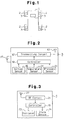
- a tire condition monitoring apparatus includes four transmitters 3 and a receiver 4.
- Each transmitter 3 corresponds to a tire 2 of a vehicle 1, and the receiver 4 is installed in the body frame of the vehicle 1. More specifically, each transmitter 3 is secured to a wheel to which the corresponding tire 2 is attached such that the transmitter 3 is located in the tire 2.
- the transmitter 3 measures the pressure and temperature in the tire 2 and wirelessly transmits data representing the measurements to the receiver 4.
- each transmitter 3 includes a controller 3, which is, for example, a microcomputer.
- the controller includes, for example, a central processing unit (CPU), a random access memory (RAM), and read only memory (ROM).
- the controller 10 stores specific identification codes and identifies the four transmitters 3 that are installed in the vehicle 1 in accordance with the associated identification codes.
- a pressure sensor 11 measures the pressure in the tire 2 and outputs pressure data that represents the measurement to the controller 1.
- a temperature sensor 14 measures the temperature in the tire 2 and outputs temperature data that represents the measurement to the controller 1.
- a battery 15 supplies power to each transmitter 3.
- a voltage sensor 16 measures voltage of the battery 15 and outputs voltage data that represents the measurement to the controller 10.
- the controller 10 transmits data that includes the pressure data, the temperature data, the voltage data, and an identification code to a transmitting circuit 12.
- the transmitting circuit 12 encodes and modulates the data received from the controller 10. The data is then wirelessly transmitted through a transmitting antenna 13.
- the controller 10 instructs the pressure sensor 11, the temperature sensor 14, and the voltage sensor 16 to perform measurements every predetermined time interval (for example, every fifteen seconds). Further, the controller 10 instructs the transmitting circuit 12 to perform a periodic transmission every time the pressure sensor 11 completes a predetermined number of measurement cycles (for example, forty cycles). When detecting an abnormal pressure or temperature of the associated tire 2, the controller 10 instructs the transmitting circuit 12 to transmit data, regardless of whether or not the pressure sensor 11 has completed the predetermined number of measurement cycles.
- the receiver 4 is powered by a battery (not shown) installed in the vehicle 1 when a key switch (not shown) of the vehicle 1, for example, is turned on.
- the receiver 4 includes a controller 20, which is, for example, a microcomputer.
- the controller 20 functions as a battery life judging means and includes, for example, a CPU, an RAM, and an ROM.
- An RF circuit 21 receives data from each transmitter 3 through at least one transmitting antenna 22.
- the RF circuit 21 demodulates and decodes the data and then sends the data to the controller 20.
- the controller 20 then reads the pressure and temperature in the associated tire 2 from the data and judges whether or not the life of the associated battery 15 is ending.
- the controller 20 instructs an indicator 23 to indicate information regarding the temperature and pressure in each tire 2 and information regarding the life of the associated battery 15.
- the indicator 23 is located to be viewed easily by the driver of the vehicle 1. Further, when detecting an abnormal temperature or pressure in one tire 2, the controller 20 instructs an alarm device 20 to inform the driver of the abnormality.
- the alarm device 20 is, for example, an audio device that produces an alarm sound or an illuminating device that emits an alarm light. Alternatively, the indicator 23 may indicate the abnormal pressure or temperature of the tire 2.
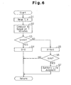
- the flowchart of Fig. 6 indicates a routine of the battery life judging process.
- the routine is repeated, for example, every time the receiver 4 receives data from one transmitter 3. Further, the routine is performed independently for each transmitter 3 of the vehicle 1.
- the data transmitted from the transmitter 3 includes its specific identification code. Thus, when the controller 20 receives data from one transmitter 3, the controller identifies the transmitter 3 in accordance with the identification code.
- step S1 the controller 20 reads the temperature T in the tire 2 associated with the transmitter 3, from which the controller 20 has received the data, and the voltage V of the associated battery 15 from the received data.
- step S2 the controller 20 computes a voltage reference value V0 in relation to the temperature T using the following equation (1). Whether or not the life of the battery 15 is ending is judged with reference to the voltage reference value V0.
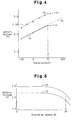
- Fig. 4 is a graph showing the relationship between the ambient temperature and the voltage of the battery 15.
- the curve Vn represents voltage variation of the battery 15 in a fully charged state.
- the curve Vu represents voltage variation of the battery 15 in an 80% discharged state.
- Fig. 5 is a graph showing the relationship between the discharge level of the battery 15 and the voltage of the battery 15.
- the curve Vh represents voltage variation of the battery 15 when the ambient temperature is twenty degrees Celsius.
- the curve Vl represents voltage variation of the battery 15 when the ambient temperature is -40 degrees Celsius.
- the graphs of Figs. 4 and 5 were obtained based on test results.
- the constants a, b of the equation (1) are selected in accordance with characteristics of the battery 15, which are indicated by the graphs of Figs. 4 and 5.
- the constants a, b are selected such that the voltage reference value V0 corresponds to the broken straight line of Fig. 4.
- the broken line is an approximation of the curve Vu, which represents the voltage variation of the battery 15 in the 80% discharged state.
- the linear function represented by the equation (1), by which the voltage reference value V0 is determined is an approximation of the curve Vu.
- the voltage reference value V0 is selected to be 2.55 volts when the ambient temperature to which the battery 15 is exposed, or the temperature T in the tire 2, is 50 degrees Celsius.
- step S2 the controller 20 proceeds to step S3, as shown in Fig. 6. More specifically, the controller 20 judges whether or not the voltage V is equal to or greater than the voltage reference value V0. If the voltage V is equal to or greater than the voltage reference value V0, the controller 20 determines that the life of the battery 15 is not ending yet. The controller 20 then proceeds to step S4. In step S4, the controller 20 resets the counter number X to zero, thus discontinuing the process.
- step S5 the controller 20 adds one to the current counter number X, thus obtaining a new counter number X.
- step S6 the controller 20 judges whether or not the counter number X is equal to or greater than a predetermined number N.
- the predetermined number N is selected to be an integer that is not smaller than one, which is, for example, three. If the counter number X is smaller than the predetermined number N, the controller 20 discontinues the process. However, if the counter number X is equal to or greater than the predetermined number N, it is indicated that the voltage V of the battery 15 has been repeatedly judged to be smaller than the voltage reference value V0 in consecutive judgment cycles corresponding to the counter number X. In this case, the controller 20 proceeds to step S7.
- step S7 the controller 20 determines that the life of the battery 15 is ending.
- the controller 20 then instructs, for example, the indicator 23 or the alarm device 24 to inform the driver that the life of the battery 15 is ending. Afterward, the controller 20 discontinues the process.
- whether or not the life of the battery 15 is ending is judged based on comparison between the voltage V of the battery 15 and the voltage reference value V0.
- the voltage reference value V0 is varied in accordance with the temperature T in the tire 2 in which the battery 15 is located. Thus, it is accurately judged whether or not the life of the battery 15 is ending, regardless of the ambient temperature to which the battery 15 is exposed.
- the equation (1) which determines the voltage reference value V0, is selected considering characteristics of the actual voltage variation of the battery 15 with respect to the ambient temperature. Accordingly, the voltage reference value V0 constantly reflects the actual voltage variation of the battery 15 that is attached to the associated transmitter 3.
- the equation (1) reflects the voltage variation of the battery 15 in the 80% discharged state with respect to the ambient temperature.
- the controller 20 accurately determines that the life of the battery 15 is ending when the discharge level of the battery 15 substantially reaches 80%. That is, in the first embodiment, the judgment regarding the life of the battery 15 is performed based on the discharge level of the battery 15.
- the voltage reference value V0 is computed in relation to the temperature T of the tire 2 using the equation (1). Since the equation (1) simply represents the linear function, the computing process of the voltage reference value V0 is easy to perform.
- the determination is highly reliable, as compared to the case in which the determination is based on a single cycle of comparison between the voltage V and the voltage reference value V0.
- the predetermined number N may be selected to be one. If this is the case, once the voltage V of the battery 15 is judged to be smaller than the voltage reference value V0, it is determined that the life of the battery 15 is ending. However, since the voltage reference value V0 is selected in accordance with the temperature T in the tire 2, the determination is still sufficiently reliable.
- FIG. 7 A second embodiment according to the present invention will hereafter be described with reference to the flowchart of Fig. 7.
- the battery life judging routine of Fig. 7 is performed instead of the routine of Fig. 6.
- Same or like reference numerals are given to steps in Fig. 7 that are the same as or like corresponding parts in Fig. 6.
- step S1 the controller 20 reads the temperature T in the tire 2 associated with the transmitter 3 and the voltage V of the associated battery 15, from the received data.
- step Sll the controller 20 judges whether or not the temperature T is equal to or greater than a predetermined reference value T0.
- the reference value T0 is a constant value which is, for example, approximately -30 degrees Celsius. If the temperature T is equal to or greater than the reference value T0, the controller 20 proceeds to step S12 and judges whether or not the life of the battery 15 is ending.
- step S12 the controller 20 judges whether or not the voltage V is equal to or greater than a predetermined voltage reference value V1.
- the voltage reference value V1 is a constant value, unlike the voltage reference value V0 of the routine of Fig. 6. If the voltage V is equal to or greater than the voltage reference value V1, the controller 20 proceeds to step S4. In contrast, if the voltage V is smaller than the voltage reference value V1, the controller 20 performs step S5.
- steps S4 to S7 is the same as that of the routine of Fig. 6. That is, if the voltage V is equal to or greater than the voltage reference value V1, it is determined that the life of the battery 15 is not ending yet. However, if the voltage V has been repeatedly judged to be smaller than the voltage reference value V1 in N consecutive judgment cycles, it is determined that the life of the battery 15 is ending.
- controller 20 determines that the temperature T in the tire 2 is smaller than the reference value T0 in step S11, the controller 20 discontinues the process without performing the judgment regarding the life of the battery 15.
- the judgment regarding the life of the battery 15 is not performed as long as the temperature T in the tire 2, or the ambient temperature to which the battery 15 is exposed, is smaller than the reference value T0. That is, if the voltage V of the battery 15 is excessively low due to the ambient temperature, the judgment is suspended. This prevents the life of the battery 15 from being erroneously judged to be ending when the temperature in the tire 2 is relatively low.
- the reference value T0 and the voltage reference value V1 are constant values, unlike the routine of Fig. 6 in which the voltage reference value V0 is changed in accordance with the temperature T in the tire 2. This simplifies the battery life judging process, and the operation of the controller 20 is also simplified.
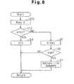
- FIG. 8 A third embodiment of the present invention will hereafter be described with reference to the flowchart of Fig. 8.
- the battery life judging process of Fig. 8 is performed, instead of the routine in Figs. 6 or 7. Same or like reference numerals are given to steps in Fig. 8 that are the same as or like corresponding parts in Figs. 6 or 7.
- the routine of Fig. 8 is essentially the same as the routine of Fig. 7 except for step S11, which is not performed in the routine of Fig. 8. More specifically, in the routine of Fig. 8, when receiving data from one transmitter 3, the controller 20 performs step S1. That is, the controller 20 reads the voltage V of the battery 15 associated with the transmitter 3 from the received data.
- step S12 the controller 20 judges whether or not the voltage V is equal to or greater than the predetermined voltage reference value V1.
- the voltage reference value V1 is a constant value. If the voltage V is equal to or greater than the voltage reference value V1, the controller 20 proceeds to step S4. In contrast, if the voltage V is smaller than the voltage reference value V1, the controller 20 proceeds to step S5.
- steps S4 to S7 of Fig. 8 is the same as the corresponding procedure of Fig. 6. That is, if the voltage V is equal to or greater than the voltage reference value V1, it is determined that the life of the battery 15 is not ending yet. However, if the voltage V has been repeatedly judged to be smaller than the voltage reference value V1 in consecutive judgment cycles corresponding to the predetermined number N, it is determined that the life of the battery 15 is ending.
- the life of the battery 15 is ending if the voltage V has been repeatedly judged to be smaller than the voltage reference value V1 in the consecutive judgment cycles.
- the judgment is reliable.
- the judgment regarding the life of the battery 15 is performed regardless of the temperature T in the tire 2.
- the temperature T gradually increases if the vehicle 1 is maintained in an operating state.
- the voltage V of the battery 15 starts to increase after a relatively short period of time in which the voltage V of the battery 15 is excessively decreased due to the ambient temperature, unless the life of the battery 15 is actually ending.
- the predetermined number N is selected to be a relatively large number, for example, eight to ten, the life of the battery 15 is prevented from being erroneously judged, even if the ambient temperature is relatively low.
- the voltage reference value V0 does not necessarily have to be determined using the equation (1) as illustrated. That is, the equation (1) may be modified depending on the type or characteristics of the battery 15, which is attached to the transmitter 3.
- the voltage reference value V0 may be determined without using the equation (1).
- a memory of the controller 20 stores data that indicates the curve Vu in the graph of Fig. 4, which represents the voltage variation of the battery 15 in the 80% discharged state.
- the controller 20 selects the voltage reference value V0 in accordance with the stored data.
- the predetermined number N may be modified depending on conditions under which the transmitter 3 is used, as long as the predetermined number N is an integer.
- the voltage reference value V1 may be modified depending on the type or characteristics of the battery 15.
- the reference value T0 may be modified depending on conditions under which the transmitter 3 is used or the type or characteristics of the battery 15.
- Each transmitter 3 does not necessarily have to include the voltage sensor 16, as long as each transmitter 3 has a sensor that measures a value that varies in relation to the voltage V of the battery 15.
- the transmitter 3 may be provided with a resistance sensor that measures resistance in an electric circuit of the transmitter 3.
- the transmitter 3 transmits data that represents the resistance, instead of data that represents the voltage V of the battery 15.
- the receiver 4 reads the resistance value from the received data and compares the value with a reference value to determine whether or not the life of the battery 15 is ending.
- the reference value may be varied in accordance with the temperature T in the tire 2 or may be a constant value.
- the battery life judging routines of Figs. 6 to 8 may be performed by the transmitters 3, instead of the receiver 4. In this case, when each transmitter 3 determines that the life of the associated battery 15 is ending, the transmitter 3 informs the receiver 4 of the state of the battery 15.
Landscapes
- Engineering & Computer Science (AREA)
- Mechanical Engineering (AREA)
- Arrangements For Transmission Of Measured Signals (AREA)
- Tires In General (AREA)
- Emergency Alarm Devices (AREA)
- Charge And Discharge Circuits For Batteries Or The Like (AREA)
- Selective Calling Equipment (AREA)
Description
- The present invention relates to apparatuses for monitoring the condition of a tire attached to a vehicle, and, more particularly, to techniques for judging the condition of a battery installed in a transmitter that is attached to a tire.
- Conventionally, a wireless, tire condition monitoring apparatus informs a driver of the condition of each tire attached to a vehicle through an indicator located in a passenger compartment. A transmitter is attached to each tire. The transmitter measures the pressure and temperature in the associated tire and wirelessly transmits data representing the measurements. A receiver is located in the vehicle's body frame and receives the data from the transmitter. The receiver obtains necessary information from the data and instructs the indicator to indicate the information as needed.
- Since each transmitter is powered by a battery, the transmitter stops operating if the associated battery's life ends. Thus, when the battery's life is ending, the driver needs to be informed of the condition of the battery through the indicator, which is located in the passenger compartment. Accordingly, the conventional monitoring apparatus transmits data representing the voltage of each battery, together with the data representing the condition of each tire. If the voltage of the battery is equal to or smaller than a predetermined reference value, the receiver judges that the life of the battery is ending. The receiver then instructs, for example, the indicator to indicate the judgment.
- However, the battery voltage is affected by the ambient temperature to which the battery is exposed. That is, the lower the ambient temperature is, the lower the battery voltage is. Particularly, the temperature variation in the tire in which the battery is located is relatively large. Thus, the condition of the battery cannot be accurately judged if the judgment is based on only the comparison between the battery voltage and the reference value. In other words, if the judgment is based only on such a comparison, the condition of the battery may be erroneously judged.
- Accordingly, it is an objective of the present invention to provide a tire condition monitoring apparatus that accurately judges the condition of a transmitter battery.
- To achieve the foregoing and other objectives and in accordance with the purpose of the present invention, the invention provides a tire condition monitoring apparatus for monitoring a condition of a tire attached to a vehicle. The apparatus includes a transmitter and a controller. Document US-A-5,335,540 discloses a similar tire monitoring apparatus. Features of said document have been used in order to form the first part of
claim 1. The transmitter is operated by a battery and detects at least the temperature in the tire and a voltage-related value that varies in accordance with voltage of the battery. The controller judges whether or not the life of the battery is ending depending on the voltage-related value. The judgment regarding the life of the battery is performed in relation to the temperature in the tire. - Other aspects and advantages of the invention will become apparent from the following description, taken in conjunction with the accompanying drawings, illustrating by way of example the principles of the invention.
- The invention, together with objects and advantages thereof, may best be understood by reference to the following description of the presently preferred embodiments together with the accompanying drawings in which:
- Fig. 1 is a view schematically showing a first embodiment of a tire condition monitoring apparatus according to the present invention;
- Fig. 2 is a block diagram showing a transmitter of the apparatus of Fig. 1;
- Fig. 3 is a block diagram showing a receiver of the apparatus of Fig. 1;
- Fig. 4 is a graph representing the relationship between battery voltage and ambient temperature;
- Fig. 5 is a graph representing the relationship between battery voltage and battery discharge level;
- Fig. 6 is a flowchart showing a battery life judging process of the first embodiment;
- Fig. 7 is a flowchart showing a battery life judging process of a second embodiment according to the present invention; and
- Fig. 8 is a flowchart showing a battery life judging process of a third embodiment according to the present invention.
- A first embodiment of the present invention will now be described with reference to Figs. 1 to 6. As shown in Fig. 1, a tire condition monitoring apparatus includes four
transmitters 3 and areceiver 4. Eachtransmitter 3 corresponds to atire 2 of avehicle 1, and thereceiver 4 is installed in the body frame of thevehicle 1. More specifically, eachtransmitter 3 is secured to a wheel to which thecorresponding tire 2 is attached such that thetransmitter 3 is located in thetire 2. Thetransmitter 3 measures the pressure and temperature in thetire 2 and wirelessly transmits data representing the measurements to thereceiver 4. - As shown in Fig. 2, each
transmitter 3 includes acontroller 3, which is, for example, a microcomputer. The controller includes, for example, a central processing unit (CPU), a random access memory (RAM), and read only memory (ROM). Thecontroller 10 stores specific identification codes and identifies the fourtransmitters 3 that are installed in thevehicle 1 in accordance with the associated identification codes. - A
pressure sensor 11 measures the pressure in thetire 2 and outputs pressure data that represents the measurement to thecontroller 1. Atemperature sensor 14 measures the temperature in thetire 2 and outputs temperature data that represents the measurement to thecontroller 1. - A battery 15 supplies power to each
transmitter 3. Avoltage sensor 16 measures voltage of the battery 15 and outputs voltage data that represents the measurement to thecontroller 10. - The
controller 10 transmits data that includes the pressure data, the temperature data, the voltage data, and an identification code to a transmittingcircuit 12. The transmittingcircuit 12 encodes and modulates the data received from thecontroller 10. The data is then wirelessly transmitted through a transmittingantenna 13. - The
controller 10 instructs thepressure sensor 11, thetemperature sensor 14, and thevoltage sensor 16 to perform measurements every predetermined time interval (for example, every fifteen seconds). Further, thecontroller 10 instructs the transmittingcircuit 12 to perform a periodic transmission every time thepressure sensor 11 completes a predetermined number of measurement cycles (for example, forty cycles). When detecting an abnormal pressure or temperature of the associatedtire 2, thecontroller 10 instructs the transmittingcircuit 12 to transmit data, regardless of whether or not thepressure sensor 11 has completed the predetermined number of measurement cycles. - As shown in Fig. 3, the
receiver 4 is powered by a battery (not shown) installed in thevehicle 1 when a key switch (not shown) of thevehicle 1, for example, is turned on. Thereceiver 4 includes acontroller 20, which is, for example, a microcomputer. Thecontroller 20 functions as a battery life judging means and includes, for example, a CPU, an RAM, and an ROM. - An
RF circuit 21 receives data from eachtransmitter 3 through at least one transmittingantenna 22. TheRF circuit 21 demodulates and decodes the data and then sends the data to thecontroller 20. Thecontroller 20 then reads the pressure and temperature in the associatedtire 2 from the data and judges whether or not the life of the associated battery 15 is ending. - The
controller 20 instructs anindicator 23 to indicate information regarding the temperature and pressure in eachtire 2 and information regarding the life of the associated battery 15. Theindicator 23 is located to be viewed easily by the driver of thevehicle 1. Further, when detecting an abnormal temperature or pressure in onetire 2, thecontroller 20 instructs analarm device 20 to inform the driver of the abnormality. Thealarm device 20 is, for example, an audio device that produces an alarm sound or an illuminating device that emits an alarm light. Alternatively, theindicator 23 may indicate the abnormal pressure or temperature of thetire 2. - Next, a battery life judging process performed by the
controller 20 will be described with reference to Fig. 6. The flowchart of Fig. 6 indicates a routine of the battery life judging process. The routine is repeated, for example, every time thereceiver 4 receives data from onetransmitter 3. Further, the routine is performed independently for eachtransmitter 3 of thevehicle 1. The data transmitted from thetransmitter 3 includes its specific identification code. Thus, when thecontroller 20 receives data from onetransmitter 3, the controller identifies thetransmitter 3 in accordance with the identification code. - Subsequently, in step S1, the
controller 20 reads the temperature T in thetire 2 associated with thetransmitter 3, from which thecontroller 20 has received the data, and the voltage V of the associated battery 15 from the received data. - In step S2, the
controller 20 computes a voltage reference value V0 in relation to the temperature T using the following equation (1). Whether or not the life of the battery 15 is ending is judged with reference to the voltage reference value V0. The numerals a, b in the equation (1) are predetermined constants that are selected depending on which type the battery 15 is.
- Fig. 4 is a graph showing the relationship between the ambient temperature and the voltage of the battery 15. In the graph, the curve Vn represents voltage variation of the battery 15 in a fully charged state. The curve Vu represents voltage variation of the battery 15 in an 80% discharged state. Fig. 5 is a graph showing the relationship between the discharge level of the battery 15 and the voltage of the battery 15. In the graph, the curve Vh represents voltage variation of the battery 15 when the ambient temperature is twenty degrees Celsius. The curve Vl represents voltage variation of the battery 15 when the ambient temperature is -40 degrees Celsius. The graphs of Figs. 4 and 5 were obtained based on test results.
- As is clear from the graphs of Figs. 4 and 5, as the discharge level of the battery 15 increases, the voltage of the battery 15 decreases. Further, as the ambient temperature to which the battery 15 is exposed decreases, the voltage of the battery 15 decreases. The constants a, b of the equation (1) are selected in accordance with characteristics of the battery 15, which are indicated by the graphs of Figs. 4 and 5. For example, the constants a, b are selected such that the voltage reference value V0 corresponds to the broken straight line of Fig. 4. The broken line is an approximation of the curve Vu, which represents the voltage variation of the battery 15 in the 80% discharged state. In other words, the linear function represented by the equation (1), by which the voltage reference value V0 is determined, is an approximation of the curve Vu. In accordance with the graph of Fig. 4, the voltage reference value V0 is selected to be 2.55 volts when the ambient temperature to which the battery 15 is exposed, or the temperature T in the
tire 2, is 50 degrees Celsius. - After completing step S2, the
controller 20 proceeds to step S3, as shown in Fig. 6. More specifically, thecontroller 20 judges whether or not the voltage V is equal to or greater than the voltage reference value V0. If the voltage V is equal to or greater than the voltage reference value V0, thecontroller 20 determines that the life of the battery 15 is not ending yet. Thecontroller 20 then proceeds to step S4. In step S4, thecontroller 20 resets the counter number X to zero, thus discontinuing the process. - In contrast, if the voltage V is smaller than the voltage reference value V0, the
controller 20 performs step S5. In step S5, thecontroller 20 adds one to the current counter number X, thus obtaining a new counter number X. - Next, in step S6, the
controller 20 judges whether or not the counter number X is equal to or greater than a predetermined number N. The predetermined number N is selected to be an integer that is not smaller than one, which is, for example, three. If the counter number X is smaller than the predetermined number N, thecontroller 20 discontinues the process. However, if the counter number X is equal to or greater than the predetermined number N, it is indicated that the voltage V of the battery 15 has been repeatedly judged to be smaller than the voltage reference value V0 in consecutive judgment cycles corresponding to the counter number X. In this case, thecontroller 20 proceeds to step S7. - In step S7, the
controller 20 determines that the life of the battery 15 is ending. Thecontroller 20 then instructs, for example, theindicator 23 or thealarm device 24 to inform the driver that the life of the battery 15 is ending. Afterward, thecontroller 20 discontinues the process. - As described, in the first embodiment, whether or not the life of the battery 15 is ending is judged based on comparison between the voltage V of the battery 15 and the voltage reference value V0. The voltage reference value V0 is varied in accordance with the temperature T in the
tire 2 in which the battery 15 is located. Thus, it is accurately judged whether or not the life of the battery 15 is ending, regardless of the ambient temperature to which the battery 15 is exposed. - The equation (1), which determines the voltage reference value V0, is selected considering characteristics of the actual voltage variation of the battery 15 with respect to the ambient temperature. Accordingly, the voltage reference value V0 constantly reflects the actual voltage variation of the battery 15 that is attached to the associated
transmitter 3. - The equation (1) reflects the voltage variation of the battery 15 in the 80% discharged state with respect to the ambient temperature. Thus, regardless of the temperature T in the
tire 2, thecontroller 20 accurately determines that the life of the battery 15 is ending when the discharge level of the battery 15 substantially reaches 80%. That is, in the first embodiment, the judgment regarding the life of the battery 15 is performed based on the discharge level of the battery 15. - Even if the discharge level of the battery 15
reaches 80%, thetransmitter 3 does not immediately stop operating. Thus, the driver of thevehicle 1 is notified that the life of the battery 15 is ending before thetransmitter 3 actually stops operating. - The voltage reference value V0 is computed in relation to the temperature T of the
tire 2 using the equation (1). Since the equation (1) simply represents the linear function, the computing process of the voltage reference value V0 is easy to perform. - If the voltage V has been repeatedly judged to be smaller than the voltage reference value V0 in consecutive judgment cycles, it is determined that the life of the battery 15 is ending. Thus, the determination is highly reliable, as compared to the case in which the determination is based on a single cycle of comparison between the voltage V and the voltage reference value V0.
- Alternatively, in step S6, the predetermined number N may be selected to be one. If this is the case, once the voltage V of the battery 15 is judged to be smaller than the voltage reference value V0, it is determined that the life of the battery 15 is ending. However, since the voltage reference value V0 is selected in accordance with the temperature T in the
tire 2, the determination is still sufficiently reliable. - A second embodiment according to the present invention will hereafter be described with reference to the flowchart of Fig. 7. In the second embodiment, the battery life judging routine of Fig. 7 is performed instead of the routine of Fig. 6. Same or like reference numerals are given to steps in Fig. 7 that are the same as or like corresponding parts in Fig. 6.
- When receiving data from one
transmitter 3, thecontroller 20 performs step S1 In step S1, as in the corresponding step of Fig. 6, thecontroller 20 reads the temperature T in thetire 2 associated with thetransmitter 3 and the voltage V of the associated battery 15, from the received data. - Subsequently, in step Sll, the
controller 20 judges whether or not the temperature T is equal to or greater than a predetermined reference value T0. The reference value T0 is a constant value which is, for example, approximately -30 degrees Celsius. If the temperature T is equal to or greater than the reference value T0, thecontroller 20 proceeds to step S12 and judges whether or not the life of the battery 15 is ending. - In step S12, the
controller 20 judges whether or not the voltage V is equal to or greater than a predetermined voltage reference value V1. The voltage reference value V1 is a constant value, unlike the voltage reference value V0 of the routine of Fig. 6. If the voltage V is equal to or greater than the voltage reference value V1, thecontroller 20 proceeds to step S4. In contrast, if the voltage V is smaller than the voltage reference value V1, thecontroller 20 performs step S5. - The procedure of steps S4 to S7 is the same as that of the routine of Fig. 6. That is, if the voltage V is equal to or greater than the voltage reference value V1, it is determined that the life of the battery 15 is not ending yet. However, if the voltage V has been repeatedly judged to be smaller than the voltage reference value V1 in N consecutive judgment cycles, it is determined that the life of the battery 15 is ending.
- If the
controller 20 determines that the temperature T in thetire 2 is smaller than the reference value T0 in step S11, thecontroller 20 discontinues the process without performing the judgment regarding the life of the battery 15. - As described, in the second embodiment, the judgment regarding the life of the battery 15 is not performed as long as the temperature T in the
tire 2, or the ambient temperature to which the battery 15 is exposed, is smaller than the reference value T0. That is, if the voltage V of the battery 15 is excessively low due to the ambient temperature, the judgment is suspended. This prevents the life of the battery 15 from being erroneously judged to be ending when the temperature in thetire 2 is relatively low. - The reference value T0 and the voltage reference value V1 are constant values, unlike the routine of Fig. 6 in which the voltage reference value V0 is changed in accordance with the temperature T in the
tire 2. This simplifies the battery life judging process, and the operation of thecontroller 20 is also simplified. - A third embodiment of the present invention will hereafter be described with reference to the flowchart of Fig. 8. In the third embodiment, the battery life judging process of Fig. 8 is performed, instead of the routine in Figs. 6 or 7. Same or like reference numerals are given to steps in Fig. 8 that are the same as or like corresponding parts in Figs. 6 or 7.
- The routine of Fig. 8 is essentially the same as the routine of Fig. 7 except for step S11, which is not performed in the routine of Fig. 8. More specifically, in the routine of Fig. 8, when receiving data from one
transmitter 3, thecontroller 20 performs step S1. That is, thecontroller 20 reads the voltage V of the battery 15 associated with thetransmitter 3 from the received data. - Subsequently, in step S12, the
controller 20 judges whether or not the voltage V is equal to or greater than the predetermined voltage reference value V1. As in the routine of Fig. 7, the voltage reference value V1 is a constant value. If the voltage V is equal to or greater than the voltage reference value V1, thecontroller 20 proceeds to step S4. In contrast, if the voltage V is smaller than the voltage reference value V1, thecontroller 20 proceeds to step S5. - The procedure of steps S4 to S7 of Fig. 8 is the same as the corresponding procedure of Fig. 6. That is, if the voltage V is equal to or greater than the voltage reference value V1, it is determined that the life of the battery 15 is not ending yet. However, if the voltage V has been repeatedly judged to be smaller than the voltage reference value V1 in consecutive judgment cycles corresponding to the predetermined number N, it is determined that the life of the battery 15 is ending.
- As described, in the third embodiment, it is determined that the life of the battery 15 is ending if the voltage V has been repeatedly judged to be smaller than the voltage reference value V1 in the consecutive judgment cycles. Thus, as compared to the case in which the judgment regarding the life of the battery 15 is performed based on a single cycle of comparison between the voltage V and the voltage reference value V1, the judgment is reliable.
- In the third embodiment, the judgment regarding the life of the battery 15 is performed regardless of the temperature T in the
tire 2. However, even when the atmospheric temperature is relatively low, the temperature T gradually increases if thevehicle 1 is maintained in an operating state. Thus, as long as thevehicle 1, or thereceiver 4, remains in the operating state, the voltage V of the battery 15 starts to increase after a relatively short period of time in which the voltage V of the battery 15 is excessively decreased due to the ambient temperature, unless the life of the battery 15 is actually ending. Accordingly, if the predetermined number N is selected to be a relatively large number, for example, eight to ten, the life of the battery 15 is prevented from being erroneously judged, even if the ambient temperature is relatively low. - The present invention is not restricted to the illustrated embodiments but may be modified as follows.
- In the routine of Fig. 6, the voltage reference value V0 does not necessarily have to be determined using the equation (1) as illustrated. That is, the equation (1) may be modified depending on the type or characteristics of the battery 15, which is attached to the
transmitter 3. - In the routine of Fig. 6, the voltage reference value V0 may be determined without using the equation (1). For example, a memory of the
controller 20 stores data that indicates the curve Vu in the graph of Fig. 4, which represents the voltage variation of the battery 15 in the 80% discharged state. Thecontroller 20 selects the voltage reference value V0 in accordance with the stored data. - In the routines of Figs. 6 to 8, the predetermined number N may be modified depending on conditions under which the
transmitter 3 is used, as long as the predetermined number N is an integer. - In the routine of Figs. 7 or 8, the voltage reference value V1 may be modified depending on the type or characteristics of the battery 15.
- In the routine of Fig. 7, the reference value T0 may be modified depending on conditions under which the
transmitter 3 is used or the type or characteristics of the battery 15. - Each
transmitter 3 does not necessarily have to include thevoltage sensor 16, as long as eachtransmitter 3 has a sensor that measures a value that varies in relation to the voltage V of the battery 15. For example, thetransmitter 3 may be provided with a resistance sensor that measures resistance in an electric circuit of thetransmitter 3. In this case, thetransmitter 3 transmits data that represents the resistance, instead of data that represents the voltage V of the battery 15. Thereceiver 4 reads the resistance value from the received data and compares the value with a reference value to determine whether or not the life of the battery 15 is ending. The reference value may be varied in accordance with the temperature T in thetire 2 or may be a constant value. - The battery life judging routines of Figs. 6 to 8 may be performed by the
transmitters 3, instead of thereceiver 4. In this case, when eachtransmitter 3 determines that the life of the associated battery 15 is ending, thetransmitter 3 informs thereceiver 4 of the state of the battery 15. - Therefore, the present examples and embodiments are to be considered as illustrative and not restrictive and the invention is not to be limited to the details given herein, but may be modified within the scope and equivalence of the appended claims.
Claims (7)
- A tire condition monitoring apparatus for monitoring a condition of a tire (2) attached to a vehicle (1), the apparatus comprising
a transmitter (3), which is adapted to operate by a battery (15) and to detect at least the temperature in the tire (2) and a voltage-related value that can vary in accordance with voltage of the battery (15); and
a controller (20), which is adapted to judge whether or not the life of the battery (15) is ending depending on the voltage-related value; being characterised in that the judgment regarding the life of the battery (15) is adapted to be performed in relation to the temperature in the tire (2). - The apparatus as set forth in claim 1, characterized in that the transmitter (3) wirelessly can transmit data, which includes data that represents the temperature in the tire (2) and data that represents the voltage-related value, and the controller (20) is located in a receiver that can receive the data from the transmitter (3).
- The apparatus as set forth in claims 1 or 2, characterized in that the controller (20) is adapted judge whether or not the life of the battery (15) is ending based on a comparison between the voltage-related value and a variable voltage reference value that is selected in accordance with the temperature in the tire (2).
- The apparatus as set forth in claim 3, characterized in that the controller (20) is adapted to determine the voltage reference value using a functional equation that represents variation of the voltage of the battery (15) with respect to the ambient temperature to which the battery (15) is exposed.
- The apparatus as set forth in claims 1 or 2, characterized in that the controller (20) is adapted to judge whether or not the life of the battery (15) is ending based on a comparison between the voltage-related value and a predetermined, constant voltage reference value if the temperature in the tire (2) is equal to or greater than a predetermined reference value, and the controller (20) is adapted to not perform the judgment regarding the life of the battery (15) if the temperature in the tire (2) is smaller than the reference value.
- The apparatus as set forth in any one of claims 3 to 5, characterized in that the controller (20) is adapted to determine that the life of the battery (15) is ending if the voltage-related value has been repeatedly judged to be smaller than the voltage reference value in consecutive judgment cycles.
- The apparatus as set forth in any one of claims 1 to 6, characterized in that the voltage-related value is the voltage of the battery (15) or a resistance in an electric circuit of the transmitter (3).
Applications Claiming Priority (2)
| Application Number | Priority Date | Filing Date | Title |
|---|---|---|---|
| JP2001140551 | 2001-05-10 | ||
| JP2001140551A JP2002331814A (en) | 2001-05-10 | 2001-05-10 | Tire condition monitoring device |
Publications (3)
| Publication Number | Publication Date |
|---|---|
| EP1256465A2 EP1256465A2 (en) | 2002-11-13 |
| EP1256465A3 EP1256465A3 (en) | 2003-08-27 |
| EP1256465B1 true EP1256465B1 (en) | 2006-08-23 |
Family
ID=18987140
Family Applications (1)
| Application Number | Title | Priority Date | Filing Date |
|---|---|---|---|
| EP01117445A Expired - Lifetime EP1256465B1 (en) | 2001-05-10 | 2001-07-19 | Tire condition monitoring apparatus |
Country Status (4)
| Country | Link |
|---|---|
| US (1) | US6965306B2 (en) |
| EP (1) | EP1256465B1 (en) |
| JP (1) | JP2002331814A (en) |
| DE (1) | DE60122474T2 (en) |
Families Citing this family (18)
| Publication number | Priority date | Publication date | Assignee | Title |
|---|---|---|---|---|
| US7161476B2 (en) | 2000-07-26 | 2007-01-09 | Bridgestone Firestone North American Tire, Llc | Electronic tire management system |
| US8266465B2 (en) | 2000-07-26 | 2012-09-11 | Bridgestone Americas Tire Operation, LLC | System for conserving battery life in a battery operated device |
| DE10392179B4 (en) * | 2002-01-14 | 2009-10-15 | Siemens Vdo Automotive Corp., Auburn Hills | Tire pressure monitoring system with an adaptation when changing from stationary to running state of the vehicle |
| JP2004062341A (en) * | 2002-07-25 | 2004-02-26 | Pacific Ind Co Ltd | Tire condition monitoring device |
| JP3997864B2 (en) * | 2002-08-14 | 2007-10-24 | トヨタ自動車株式会社 | Wheel state acquisition device and vehicle state acquisition device |
| JP4347601B2 (en) * | 2003-04-14 | 2009-10-21 | 横浜ゴム株式会社 | Wheel information acquisition system and wheel mounting position information setting device |
| CN1290717C (en) * | 2003-05-25 | 2006-12-20 | 朱鹏飞 | Abrupt deceleration fault pre-warning system for automobile tire and machine |
| JP4386773B2 (en) | 2004-03-22 | 2009-12-16 | 横浜ゴム株式会社 | Tire side mounted electronic device |
| GB0411156D0 (en) * | 2004-05-19 | 2004-06-23 | Powtier Controls Ltd | Wireless sensors |
| JP4569570B2 (en) * | 2004-12-15 | 2010-10-27 | 横浜ゴム株式会社 | Wheel information acquisition system |
| JP4289561B2 (en) * | 2004-12-24 | 2009-07-01 | 横浜ゴム株式会社 | Vehicle abnormality detection method and apparatus, and sensor unit thereof |
| JP4894292B2 (en) * | 2006-02-23 | 2012-03-14 | 横浜ゴム株式会社 | Tire condition detection device |
| DE102007014097A1 (en) * | 2007-03-21 | 2008-09-25 | Continental Teves Ag & Co. Ohg | Tyre module for recording tyre condition variables in motor vehicle tyres, has battery-operated energy supply unit with two or multiple individual batteries of the energy supply unit is switched in parallel manner |
| US7714707B2 (en) * | 2007-05-18 | 2010-05-11 | Trw Automotive U.S. Llc | System for measuring life expectancy of a tire condition monitoring system |
| US8612066B2 (en) * | 2008-03-28 | 2013-12-17 | Caterpillar Inc. | Control system for payload limiting of hauling operation |
| JP7381428B2 (en) * | 2020-09-30 | 2023-11-15 | 株式会社ブリヂストン | Tire condition monitoring system, battery discharge capacity estimation program, and discharge capacity estimation method |
| JP2025037106A (en) * | 2023-09-05 | 2025-03-17 | 株式会社ブリヂストン | Battery life prediction device and battery life prediction method |
| JP2025037107A (en) * | 2023-09-05 | 2025-03-17 | 株式会社ブリヂストン | Battery life prediction device and battery life prediction method |
Family Cites Families (9)
| Publication number | Priority date | Publication date | Assignee | Title |
|---|---|---|---|---|
| US5231872A (en) * | 1991-02-21 | 1993-08-03 | Ttc/Truck Tech Corp. | Tire monitoring apparatus and method |
| US5500065A (en) * | 1994-06-03 | 1996-03-19 | Bridgestone/Firestone, Inc. | Method for embedding a monitoring device within a tire during manufacture |
| WO1996006747A2 (en) * | 1994-08-31 | 1996-03-07 | Otter Controls Limited | A tyre condition monitoring system |
| US5783992A (en) * | 1996-07-22 | 1998-07-21 | Delco Electronics Corp. | Time based low tire pressure warning sensor |
| US6252498B1 (en) * | 1998-03-03 | 2001-06-26 | Charles Pashayan, Jr. | Tire pressure detecting system for a vehicle |
| DE19856860A1 (en) * | 1998-12-09 | 2000-06-21 | Beru Ag | Method for operating a device for monitoring and wireless signaling of a pressure change in pneumatic tires on vehicles |
| US6232875B1 (en) * | 2000-06-27 | 2001-05-15 | Trw Inc. | Apparatus and method for controlling a tire condition module of a vehicle tire |
| US6580364B1 (en) * | 2000-07-06 | 2003-06-17 | Trw Inc. | Apparatus and method for tracking an abnormal tire condition |
| US6340930B1 (en) * | 2001-03-07 | 2002-01-22 | Trw Inc. | System and method for monitoring a condition of a vehicle tire |
-
2001
- 2001-05-10 JP JP2001140551A patent/JP2002331814A/en active Pending
- 2001-07-13 US US09/905,317 patent/US6965306B2/en not_active Expired - Fee Related
- 2001-07-19 EP EP01117445A patent/EP1256465B1/en not_active Expired - Lifetime
- 2001-07-19 DE DE60122474T patent/DE60122474T2/en not_active Expired - Fee Related
Also Published As
| Publication number | Publication date |
|---|---|
| DE60122474D1 (en) | 2006-10-05 |
| EP1256465A2 (en) | 2002-11-13 |
| US6965306B2 (en) | 2005-11-15 |
| US20020167400A1 (en) | 2002-11-14 |
| EP1256465A3 (en) | 2003-08-27 |
| JP2002331814A (en) | 2002-11-19 |
| DE60122474T2 (en) | 2007-01-11 |
Similar Documents
| Publication | Publication Date | Title |
|---|---|---|
| US6965306B2 (en) | Tire condition monitoring apparatus | |
| US6938467B2 (en) | Transmitter of tire condition monitoring apparatus | |
| KR100370741B1 (en) | Tire air pressure monitoring apparatus and method | |
| US6612165B2 (en) | Tire pressure monitoring system with pressure gauge operating mode for indicating when air pressure within a tire is within a predetermined pressure range | |
| US6450021B1 (en) | Transmitter and transmitting method of tire air pressure monitoring apparatus | |
| EP1323552B1 (en) | Tire condition monitoring apparatus | |
| US6963274B2 (en) | Transmitter of tire condition monitoring apparatus and tire condition monitoring apparatus | |
| US6983649B2 (en) | Tire condition monitoring apparatus | |
| US6580364B1 (en) | Apparatus and method for tracking an abnormal tire condition | |
| US6972691B2 (en) | Tire condition monitoring apparatus | |
| US20040095231A1 (en) | Tire monitoring system | |
| US6958686B2 (en) | Transmitter for tire condition monitoring apparatus and tire condition monitoring apparatus | |
| EP1306234A1 (en) | Tire condition monitoring apparatus | |
| EP1630009A2 (en) | Tire condition monitoring apparatus transmitter, and receiver | |
| EP1619052A1 (en) | Tire alarm device | |
| US11833864B2 (en) | Tire pressure monitoring system | |
| US7369043B2 (en) | Method and apparatus for automatically identifying the location of pressure sensors in a tire pressure monitoring system | |
| EP1270276B1 (en) | Tire condition monitoring apparatus | |
| US7714707B2 (en) | System for measuring life expectancy of a tire condition monitoring system | |
| EP1384605B1 (en) | Tire condition monitoring apparatus |
Legal Events
| Date | Code | Title | Description |
|---|---|---|---|
| PUAI | Public reference made under article 153(3) epc to a published international application that has entered the european phase |
Free format text: ORIGINAL CODE: 0009012 |
|
| AK | Designated contracting states |
Kind code of ref document: A2 Designated state(s): AT BE CH CY DE DK ES FI FR GB GR IE IT LI LU MC NL PT SE TR |
|
| AX | Request for extension of the european patent |
Free format text: AL;LT;LV;MK;RO;SI |
|
| PUAL | Search report despatched |
Free format text: ORIGINAL CODE: 0009013 |
|
| AK | Designated contracting states |
Designated state(s): AT BE CH CY DE DK ES FI FR GB GR IE IT LI LU MC NL PT SE TR |
|
| AX | Request for extension of the european patent |
Extension state: AL LT LV MK RO SI |
|
| 17P | Request for examination filed |
Effective date: 20040204 |
|
| AKX | Designation fees paid |
Designated state(s): DE FR GB |
|
| GRAP | Despatch of communication of intention to grant a patent |
Free format text: ORIGINAL CODE: EPIDOSNIGR1 |
|
| RIN1 | Information on inventor provided before grant (corrected) |
Inventor name: KATOU, MICHIYA,C/O PACIFIC INDUSTRIAL CO., LTD. Inventor name: TSUJITA, YASUHISA,PACIFIC INDUSTRIAL CO., LTD. |
|
| GRAS | Grant fee paid |
Free format text: ORIGINAL CODE: EPIDOSNIGR3 |
|
| GRAA | (expected) grant |
Free format text: ORIGINAL CODE: 0009210 |
|
| AK | Designated contracting states |
Kind code of ref document: B1 Designated state(s): DE FR GB |
|
| REG | Reference to a national code |
Ref country code: GB Ref legal event code: FG4D |
|
| REF | Corresponds to: |
Ref document number: 60122474 Country of ref document: DE Date of ref document: 20061005 Kind code of ref document: P |
|
| ET | Fr: translation filed | ||
| PLBE | No opposition filed within time limit |
Free format text: ORIGINAL CODE: 0009261 |
|
| STAA | Information on the status of an ep patent application or granted ep patent |
Free format text: STATUS: NO OPPOSITION FILED WITHIN TIME LIMIT |
|
| 26N | No opposition filed |
Effective date: 20070524 |
|
| GBPC | Gb: european patent ceased through non-payment of renewal fee |
Effective date: 20070719 |
|
| PG25 | Lapsed in a contracting state [announced via postgrant information from national office to epo] |
Ref country code: DE Free format text: LAPSE BECAUSE OF NON-PAYMENT OF DUE FEES Effective date: 20080201 |
|
| PG25 | Lapsed in a contracting state [announced via postgrant information from national office to epo] |
Ref country code: GB Free format text: LAPSE BECAUSE OF NON-PAYMENT OF DUE FEES Effective date: 20070719 |
|
| REG | Reference to a national code |
Ref country code: FR Ref legal event code: ST Effective date: 20080331 |
|
| PG25 | Lapsed in a contracting state [announced via postgrant information from national office to epo] |
Ref country code: FR Free format text: LAPSE BECAUSE OF NON-PAYMENT OF DUE FEES Effective date: 20070731 |