EP1255405A1 - Mechanical system for adjusting image centering and rotation in projection television apparatus - Google Patents
Mechanical system for adjusting image centering and rotation in projection television apparatus Download PDFInfo
- Publication number
- EP1255405A1 EP1255405A1 EP02291082A EP02291082A EP1255405A1 EP 1255405 A1 EP1255405 A1 EP 1255405A1 EP 02291082 A EP02291082 A EP 02291082A EP 02291082 A EP02291082 A EP 02291082A EP 1255405 A1 EP1255405 A1 EP 1255405A1
- Authority
- EP
- European Patent Office
- Prior art keywords
- bracket
- cam
- adjuster
- rotation
- ability
- Prior art date
- Legal status (The legal status is an assumption and is not a legal conclusion. Google has not performed a legal analysis and makes no representation as to the accuracy of the status listed.)
- Granted
Links
Images


Classifications
-
- H—ELECTRICITY
- H04—ELECTRIC COMMUNICATION TECHNIQUE
- H04N—PICTORIAL COMMUNICATION, e.g. TELEVISION
- H04N5/00—Details of television systems
- H04N5/74—Projection arrangements for image reproduction, e.g. using eidophor
-
- H—ELECTRICITY
- H04—ELECTRIC COMMUNICATION TECHNIQUE
- H04N—PICTORIAL COMMUNICATION, e.g. TELEVISION
- H04N9/00—Details of colour television systems
- H04N9/12—Picture reproducers
- H04N9/31—Projection devices for colour picture display, e.g. using electronic spatial light modulators [ESLM]
- H04N9/3141—Constructional details thereof
-
- H—ELECTRICITY
- H04—ELECTRIC COMMUNICATION TECHNIQUE
- H04N—PICTORIAL COMMUNICATION, e.g. TELEVISION
- H04N9/00—Details of colour television systems
- H04N9/12—Picture reproducers
- H04N9/31—Projection devices for colour picture display, e.g. using electronic spatial light modulators [ESLM]
- H04N9/3141—Constructional details thereof
- H04N9/317—Convergence or focusing systems
Definitions
- This invention relates to projection television apparatus, and is particularly advantageous with liquid crystal display (LCD) projection systems.
- LCD liquid crystal display
- LCD projectors electronic adjustment of centering and rotation adversely impacts picture performance.
- electronic centering there must be extra pixels outside of the image area to accommodate image shift. Therefore, some of the pixels are unused and resolution is reduced.
- electronic rotation of the image there is a similar result of wasted pixels, as well as a digital "stair-stepping" effect that occurs when a horizontal or vertical line is rotated and mapped to a rectangular pixel array.
- the projectors used in projection television apparatus must be properly adjusted in order to provide maximum picture accuracy.
- This invention allows a projector to be finely positioned such that the projected image is corrected to provide aiming and rotational accuracy.
- a mating part rigidly coupled to a housing for said television apparatus, is rigidly coupled to an overhanging arm.
- the bracket is sandwiched between the overhanging arm and the mating part.
- Another advantageous feature of the invention is that a mating part, rigidly coupled to a housing for the television apparatus, is urged toward a cam by a compression spring.
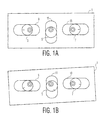
- Figure 1a shows the cams in their nominal positions. Rotation of cam 5 produces horizontal motion of bracket 1 in an X direction. Rotation of cams 3 and 7 in the same direction produces vertical motion of bracket 1 in a Y direction. Differential rotation of cams 3 and 7 causes bracket 1 to rotate, as shown in Figure 1b. Note that in Figure 1b, cam 5 has been rotated by a small amount, which also translates bracket 1 in a horizontal direction.
- a feature of the invention comprises a cam serving double duty as both a hold-down function and an adjustment function.
- mating part 15, which is rigidly coupled to a housing for the television apparatus is held to bracket 1 by the cam arrangement. Only one of the three cams is shown in Figure 2. However, the structure of the other cams is similar.
- Cam 5 has a flange 17 which holds bracket 1 to mating part 15. Screw 19 threads into mating part 15, through shoulder bushing 21, wavy washer spring 23 and cam 5. Because the thickness of cam 5 is matched to the thickness of bracket 1, flange 17 holds bracket 1 in frictional engagement with mating part 15, the amount of friction being determined by the pressure exerted by wavy washer spring 23.
- Preventing one cam from moving when another one is being adjusted is accomplished by using a screw 19, shoulder bushing 21 and a compression spring 23 to generate a clamp load between the cam and the mating part 15, such that a frictional force counteracts rotation.
- the amount of friction is selected such that a cam does not inadvertently turn too easily, but that it is not too difficult for a person to rotate a cam by hand with a simple tool.
- the wavy washer spring also does not have the problem of "winding” and “unwinding” as the cams are turned. Such winding and unwinding tends to undesirably add to the variability of the rotary force needed to turn the cam.
Landscapes
- Engineering & Computer Science (AREA)
- Multimedia (AREA)
- Signal Processing (AREA)
- Projection Apparatus (AREA)
- Devices For Indicating Variable Information By Combining Individual Elements (AREA)
- Liquid Crystal (AREA)
- Transforming Electric Information Into Light Information (AREA)
- Video Image Reproduction Devices For Color Tv Systems (AREA)
Abstract
Description
- Many systems use electronic adjustment of image centering and rotation. This invention relates to projection television apparatus, and is particularly advantageous with liquid crystal display (LCD) projection systems. With LCD projectors, electronic adjustment of centering and rotation adversely impacts picture performance. For electronic centering, there must be extra pixels outside of the image area to accommodate image shift. Therefore, some of the pixels are unused and resolution is reduced. For electronic rotation of the image, there is a similar result of wasted pixels, as well as a digital "stair-stepping" effect that occurs when a horizontal or vertical line is rotated and mapped to a rectangular pixel array.
- The projectors used in projection television apparatus must be properly adjusted in order to provide maximum picture accuracy. This invention allows a projector to be finely positioned such that the projected image is corrected to provide aiming and rotational accuracy.
- This invention provides an adjuster for positioning an element in a projection television apparatus. The adjuster comprises a bracket that mounts the element. First, second and third eccentric cams, positioned in substantially the same plane, mate with first, second and third slots in the bracket. The first cam has the ability to move the bracket in an X direction. The second cam has the ability to move the bracket in a Y direction perpendicular to said X direction, and the third cam has the ability to rotate the bracket in a plane defined by the X and Y directions.
- An advantageous feature of the invention is that at least one of the cams provides both an adjustment function and a hold-down function.
- Another advantageous feature of the invention is that means prevent one of the cams from moving when another cam is being adjusted.
- Another advantageous feature of the invention is that at least one cam has a flange and matches the thickness of the slotted bracket.
- Another advantageous feature of the invention is that a mating part, rigidly coupled to a housing for said television apparatus, is rigidly coupled to an overhanging arm. The bracket is sandwiched between the overhanging arm and the mating part.
- Another advantageous feature of the invention is that the overhanging arm has an interference hump bearing against the bracket.
- Another advantageous feature of the invention is that a mating part, rigidly coupled to a housing for the television apparatus, is urged toward a cam by a compression spring.
- Another advantageous feature of the invention is that the compression spring is a wavy washer.
- In the drawing:
- Figures 1a and 1b show the cam arrangement of the invention in two different positions.
- Figure 2 is a cross section view of the inventive cam mechanism.
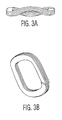
- Figures 3a, 3b, 3c and 3d are views of a wavy washer used with the inventive cam mechanism.
-
- Referring to Figures 1a and 1b, the invention provides a slotted bracket 1 that mounts the projector, and an eccentric cam arrangement that allows the bracket to be positioned accurately over a limited range. By using three
cams 3, 5, and 7, in threeslots - Figure 1a shows the cams in their nominal positions. Rotation of
cam 5 produces horizontal motion of bracket 1 in an X direction. Rotation of cams 3 and 7 in the same direction produces vertical motion of bracket 1 in a Y direction. Differential rotation of cams 3 and 7 causes bracket 1 to rotate, as shown in Figure 1b. Note that in Figure 1b,cam 5 has been rotated by a small amount, which also translates bracket 1 in a horizontal direction. - A feature of the invention comprises a cam serving double duty as both a hold-down function and an adjustment function. Referring to Figure 2,
mating part 15, which is rigidly coupled to a housing for the television apparatus, is held to bracket 1 by the cam arrangement. Only one of the three cams is shown in Figure 2. However, the structure of the other cams is similar. Cam 5 has aflange 17 which holds bracket 1 to matingpart 15. Screw 19 threads intomating part 15, through shoulder bushing 21,wavy washer spring 23 andcam 5. Because the thickness ofcam 5 is matched to the thickness of bracket 1,flange 17 holds bracket 1 in frictional engagement withmating part 15, the amount of friction being determined by the pressure exerted bywavy washer spring 23. - Mating
part 15 has an overhangingarm 25 which assists in keepingbracket 11 in contact withmating part 15. Overhangingarm 25 has aninterference hump 27 which bears against bracket 1 without unduly increasing the friction therebetween. - Another feature of the invention is to prevent one cam from moving when another cam is being adjusted.
Flange 17 causes bracket 1 to be frictionally engaged withmating part 15. When one cam is adjusted, the other cams maintain their positions by virtue of their frictional engagement withmating part 15. As a result, each cam can be adjusted with minimal motion of the other cams. - Preventing one cam from moving when another one is being adjusted is accomplished by using a
screw 19, shoulder bushing 21 and acompression spring 23 to generate a clamp load between the cam and themating part 15, such that a frictional force counteracts rotation. The amount of friction is selected such that a cam does not inadvertently turn too easily, but that it is not too difficult for a person to rotate a cam by hand with a simple tool. - A preferred embodiment uses an edge wound
wavy spring washer 23, as shown in Figures 3a, 3b, 3c and 3d, to generate the high compression load needed between the cam and the mating part. Such an arrangement is able to fit in a compact space. - A benefit of using a wavy washer as the
spring 23, instead of a helical wire spring, is the inherent "rounded" contact surfaces between the spring and the mating parts, shoulder bushing 21 andcam 5. By having these rounded contact surfaces, the amount of digging and galling caused by the spring to the mating parts is minimized. This allows the spring to directly contact a plastic cam without the added cost or bulk of a metal washer. The wavy washer spring also does not have the problem of "winding" and "unwinding" as the cams are turned. Such winding and unwinding tends to undesirably add to the variability of the rotary force needed to turn the cam.
Claims (9)
- An adjuster for positioning an element in a projection television apparatus, said adjuster comprising:a bracket that mounts said element;first, second and third eccentric cams positioned in substantially the same plane:first, second and third slots in said bracket each mated with a respective one of said cams;rotation of said first cam having the ability to move said bracket in an X direction;rotation of said second cam having the ability to move said bracket in a Y direction perpendicular to said X direction; androtation of said third cam having the ability to rotate said bracket in a plane defined by said X and Y directions.
- An adjuster as in Claim 1, in which at least one of said cams provides both an adjustment function and a hold-down function.
- An adjuster as in Claim 1, comprising:means for preventing one of said cams from moving when another cam is being adjusted.
- An adjuster as in Claim 1 in which at least one cam has a flange, and in which the thickness of said cam matches the thickness of said slotted bracket.
- An adjuster as in Claim 1, comprising:a mating part rigidly coupled to a housing for said television apparatus;an overhanging arm rigidly coupled to said mating part;said bracket being sandwiched between said overhanging arm and said mating part.
- An adjuster as in Claim 5, in which said overhanging arm has an interference hump bearing against said bracket.
- An adjuster as in Claim 1, comprising:a mating part rigidly coupled to a housing for said television apparatus; anda compression spring positioned to urge a cam toward said mating part.
- An adjuster as in Claim 1, in which said compression spring is a wavy washer.
- An adjuster for positioning an element, said adjuster comprising:a bracket that mounts said element;first, second and third eccentric cams positioned in substantially the same plane:first, second and third slots in said bracket each mated with a respective one of said cams;rotation of said first cam having the ability to move said bracket in an X direction;rotation of said second cam having the ability to move said bracket in a Y direction perpendicular to said X direction; androtation of said third cam having the ability to rotate said bracket in a plane defined by said X and Y directions.
Applications Claiming Priority (2)
| Application Number | Priority Date | Filing Date | Title |
|---|---|---|---|
| US28821701P | 2001-05-02 | 2001-05-02 | |
| US288217P | 2001-05-02 |
Publications (2)
| Publication Number | Publication Date |
|---|---|
| EP1255405A1 true EP1255405A1 (en) | 2002-11-06 |
| EP1255405B1 EP1255405B1 (en) | 2004-11-03 |
Family
ID=23106236
Family Applications (1)
| Application Number | Title | Priority Date | Filing Date |
|---|---|---|---|
| EP02291082A Expired - Lifetime EP1255405B1 (en) | 2001-05-02 | 2002-04-30 | Mechanical system for adjusting image centering and rotation in projection television apparatus |
Country Status (6)
| Country | Link |
|---|---|
| EP (1) | EP1255405B1 (en) |
| JP (1) | JP4267251B2 (en) |
| KR (1) | KR100867975B1 (en) |
| CN (1) | CN1236604C (en) |
| DE (1) | DE60201773T2 (en) |
| MX (1) | MXPA02004352A (en) |
Cited By (1)
| Publication number | Priority date | Publication date | Assignee | Title |
|---|---|---|---|---|
| CN110249250A (en) * | 2017-02-08 | 2019-09-17 | 索尼公司 | Lens adjustment mechanism and projection display device |
Families Citing this family (2)
| Publication number | Priority date | Publication date | Assignee | Title |
|---|---|---|---|---|
| EP1255405B1 (en) * | 2001-05-02 | 2004-11-03 | Thomson Licensing S.A. | Mechanical system for adjusting image centering and rotation in projection television apparatus |
| DE102006007188A1 (en) * | 2006-02-15 | 2007-08-30 | Deutsche Thomson Ohg | bracket |
Citations (3)
| Publication number | Priority date | Publication date | Assignee | Title |
|---|---|---|---|---|
| EP0735410A2 (en) * | 1995-03-31 | 1996-10-02 | Daewoo Electronics Co., Ltd | Three beam-type projection apparatus |
| EP0939548A2 (en) * | 1998-02-27 | 1999-09-01 | Mitsubishi Denki Kabushiki Kaisha | Projection-type display device |
| EP1137275A2 (en) * | 2000-01-27 | 2001-09-26 | Thomson Licensing S.A. | Spherical mounting detail for adjusting three axis of rotation without affecting centering |
Family Cites Families (3)
| Publication number | Priority date | Publication date | Assignee | Title |
|---|---|---|---|---|
| KR100266580B1 (en) * | 1997-08-12 | 2000-09-15 | 구자홍 | Apparatus for compensating keystone of lcd projection television |
| KR19990074085A (en) * | 1998-03-06 | 1999-10-05 | 구자홍 | Projection TV's Screen Distortion Correction Device |
| EP1255405B1 (en) * | 2001-05-02 | 2004-11-03 | Thomson Licensing S.A. | Mechanical system for adjusting image centering and rotation in projection television apparatus |
-
2002
- 2002-04-30 EP EP02291082A patent/EP1255405B1/en not_active Expired - Lifetime
- 2002-04-30 DE DE60201773T patent/DE60201773T2/en not_active Expired - Lifetime
- 2002-04-30 CN CNB02118965XA patent/CN1236604C/en not_active Expired - Fee Related
- 2002-04-30 JP JP2002128490A patent/JP4267251B2/en not_active Expired - Fee Related
- 2002-04-30 MX MXPA02004352A patent/MXPA02004352A/en active IP Right Grant
- 2002-05-01 KR KR1020020023891A patent/KR100867975B1/en not_active Expired - Fee Related
Patent Citations (3)
| Publication number | Priority date | Publication date | Assignee | Title |
|---|---|---|---|---|
| EP0735410A2 (en) * | 1995-03-31 | 1996-10-02 | Daewoo Electronics Co., Ltd | Three beam-type projection apparatus |
| EP0939548A2 (en) * | 1998-02-27 | 1999-09-01 | Mitsubishi Denki Kabushiki Kaisha | Projection-type display device |
| EP1137275A2 (en) * | 2000-01-27 | 2001-09-26 | Thomson Licensing S.A. | Spherical mounting detail for adjusting three axis of rotation without affecting centering |
Cited By (2)
| Publication number | Priority date | Publication date | Assignee | Title |
|---|---|---|---|---|
| CN110249250A (en) * | 2017-02-08 | 2019-09-17 | 索尼公司 | Lens adjustment mechanism and projection display device |
| CN110249250B (en) * | 2017-02-08 | 2021-10-01 | 索尼公司 | Lens adjustment mechanism and projection display device |
Also Published As
| Publication number | Publication date |
|---|---|
| EP1255405B1 (en) | 2004-11-03 |
| MXPA02004352A (en) | 2004-08-12 |
| DE60201773D1 (en) | 2004-12-09 |
| KR20020084808A (en) | 2002-11-11 |
| JP4267251B2 (en) | 2009-05-27 |
| CN1236604C (en) | 2006-01-11 |
| JP2003046909A (en) | 2003-02-14 |
| DE60201773T2 (en) | 2005-11-24 |
| KR100867975B1 (en) | 2008-11-11 |
| CN1384666A (en) | 2002-12-11 |
Similar Documents
| Publication | Publication Date | Title |
|---|---|---|
| JP3205857B2 (en) | Rod fixing device and camera stand using the same | |
| US5949087A (en) | Apparatus and method for positionally enhancing an image | |
| US7782547B2 (en) | Mechanism for controlling position of optical element | |
| US7901090B2 (en) | Adjustable reflective mirror module and projection apparatus using the same | |
| US8041204B2 (en) | Mechanism for controlling position of optical element | |
| US20090015802A1 (en) | Adjusting mechanism of light integration rod module, optical engine and projection apparatus | |
| US20070081131A1 (en) | Rotatable projection lens for rear-projection applications | |
| US6922216B2 (en) | Mechanical system for adjusting image centering and rotation in projection television apparatus | |
| EP1255405B1 (en) | Mechanical system for adjusting image centering and rotation in projection television apparatus | |
| US20200341354A1 (en) | Adjustment device and projection device using the same | |
| US7760266B2 (en) | Digital camera | |
| JP2017138517A (en) | projector | |
| JP6146960B2 (en) | Lens barrel and optical equipment using it | |
| US11681208B2 (en) | Projector | |
| US20210160402A1 (en) | Camera with lockable axes of rotation | |
| US10345549B2 (en) | Lens adjusting mechanism | |
| US6494583B2 (en) | Mirror adjustment mechanism for liquid crystal projector | |
| US9019625B2 (en) | Lens advancing device, imaging device equipped with lens advancing device, and portable electronic device | |
| JPH0618962A (en) | Field-of-view adjuster for viewfinder | |
| JP2606943Y2 (en) | Viewfinder parallax adjustment mechanism | |
| JP3313921B2 (en) | Optical equipment | |
| JP2003222924A (en) | Camera | |
| JP3125185B2 (en) | Mount shift device for lens for CCTV camera | |
| JP2009244585A (en) | Lens barrel | |
| KR200291315Y1 (en) | Movable mirror unit for optical apparatus |
Legal Events
| Date | Code | Title | Description |
|---|---|---|---|
| PUAI | Public reference made under article 153(3) epc to a published international application that has entered the european phase |
Free format text: ORIGINAL CODE: 0009012 |
|
| AK | Designated contracting states |
Kind code of ref document: A1 Designated state(s): AT BE CH CY DE DK ES FI FR GB GR IE IT LI LU MC NL PT SE TR |
|
| AX | Request for extension of the european patent |
Free format text: AL;LT;LV;MK;RO;SI |
|
| AKX | Designation fees paid | ||
| DBV | Designated contracting states (deleted) | ||
| REG | Reference to a national code |
Ref country code: DE Ref legal event code: 8566 |
|
| 17P | Request for examination filed |
Effective date: 20030423 |
|
| RBV | Designated contracting states (corrected) |
Designated state(s): DE GB |
|
| 17Q | First examination report despatched |
Effective date: 20030915 |
|
| GRAP | Despatch of communication of intention to grant a patent |
Free format text: ORIGINAL CODE: EPIDOSNIGR1 |
|
| GRAS | Grant fee paid |
Free format text: ORIGINAL CODE: EPIDOSNIGR3 |
|
| GRAA | (expected) grant |
Free format text: ORIGINAL CODE: 0009210 |
|
| AK | Designated contracting states |
Kind code of ref document: B1 Designated state(s): DE GB |
|
| REG | Reference to a national code |
Ref country code: GB Ref legal event code: FG4D |
|
| REF | Corresponds to: |
Ref document number: 60201773 Country of ref document: DE Date of ref document: 20041209 Kind code of ref document: P |
|
| REG | Reference to a national code |
Ref country code: IE Ref legal event code: FG4D |
|
| PLBE | No opposition filed within time limit |
Free format text: ORIGINAL CODE: 0009261 |
|
| STAA | Information on the status of an ep patent application or granted ep patent |
Free format text: STATUS: NO OPPOSITION FILED WITHIN TIME LIMIT |
|
| RAP2 | Party data changed (patent owner data changed or rights of a patent transferred) |
Owner name: THOMSON LICENSING |
|
| 26N | No opposition filed |
Effective date: 20050804 |
|
| PGFP | Annual fee paid to national office [announced via postgrant information from national office to epo] |
Ref country code: GB Payment date: 20160421 Year of fee payment: 15 Ref country code: DE Payment date: 20160411 Year of fee payment: 15 |
|
| REG | Reference to a national code |
Ref country code: DE Ref legal event code: R119 Ref document number: 60201773 Country of ref document: DE |
|
| GBPC | Gb: european patent ceased through non-payment of renewal fee |
Effective date: 20170430 |
|
| PG25 | Lapsed in a contracting state [announced via postgrant information from national office to epo] |
Ref country code: DE Free format text: LAPSE BECAUSE OF NON-PAYMENT OF DUE FEES Effective date: 20171103 |
|
| PG25 | Lapsed in a contracting state [announced via postgrant information from national office to epo] |
Ref country code: GB Free format text: LAPSE BECAUSE OF NON-PAYMENT OF DUE FEES Effective date: 20170430 |