EP1255325A1 - Female electrical terminal - Google Patents
Female electrical terminal Download PDFInfo
- Publication number
- EP1255325A1 EP1255325A1 EP02076493A EP02076493A EP1255325A1 EP 1255325 A1 EP1255325 A1 EP 1255325A1 EP 02076493 A EP02076493 A EP 02076493A EP 02076493 A EP02076493 A EP 02076493A EP 1255325 A1 EP1255325 A1 EP 1255325A1
- Authority
- EP
- European Patent Office
- Prior art keywords
- arm
- arms
- opposed
- free end
- electrical terminal
- Prior art date
- Legal status (The legal status is an assumption and is not a legal conclusion. Google has not performed a legal analysis and makes no representation as to the accuracy of the status listed.)
- Withdrawn
Links
- 230000013011 mating Effects 0.000 claims abstract description 22
- 239000007769 metal material Substances 0.000 claims description 2
Images


Classifications
-
- H—ELECTRICITY
- H01—ELECTRIC ELEMENTS
- H01R—ELECTRICALLY-CONDUCTIVE CONNECTIONS; STRUCTURAL ASSOCIATIONS OF A PLURALITY OF MUTUALLY-INSULATED ELECTRICAL CONNECTING ELEMENTS; COUPLING DEVICES; CURRENT COLLECTORS
- H01R13/00—Details of coupling devices of the kinds covered by groups H01R12/70 or H01R24/00 - H01R33/00
- H01R13/02—Contact members
- H01R13/10—Sockets for co-operation with pins or blades
- H01R13/11—Resilient sockets
- H01R13/113—Resilient sockets co-operating with pins or blades having a rectangular transverse section
Definitions
- the present invention relates to a female electrical terminal for mating with a flat blade contact.
- a female electrical terminal for mating with a flat blade contact is known.
- the known female terminal comprises four substantially identical arms, two on each side of the blade contact. Each arm acts like a cantilever beam with one end being pivotally mounted, and the other end being free.
- a contact area is formed in each arm adjacent the free end thereof. The contact areas are aligned on a plane substantially perpendicular to the mating axis between the terminal and the blade contact.
- a disadvantage of this known design is that the blade contact can pivot (relative to the terminal) about the axis on which the contact areas are aligned. This risks loss of contact, and damage to the surface of the blade contact and/or the contact areas of the arms of the female terminal.
- a female electrical terminal in accordance with the present invention is characterised by the features specified in Claim 1.
- the present invention provides a female electrical terminal in which the risk of the blade contact pivoting relative to the female terminal during mating and during use is substantially reduced.
- the female electrical terminal 10 in accordance with the present invention is for mating with a flat blade contact 12.
- the terminal 10 comprises first, second, third and fourth arms 14, 16, 18, 20 respectively.
- the first and second arms 14, 16 are positioned on one side 22 of the flat blade contact 12 and extend in the mating direction X.
- the third and fourth arms 18, 20 are positioned on the other side 24 of the flat blade contact 12 and also extend in the mating direction X.
- the first and second arms 14, 16 are pivotally mounted at one end 26, 28 respectively on a first pivot axis A, and have a free end 30, 32 respectively opposed to their pivot end.
- the third and fourth arms 18,20 are pivotally mounted at one end 34, 36 respectively on a second pivot axis B, and have a free end 38, 40 respectively opposed to their pivot end.
- the arms 14-20 therefore act like a cantilever beam.
- the first arm 14 is positioned opposed to the fourth arm 20, and the second arm 16 is positioned opposed to the third arm 18.
- Each arm 14-20 has a contact area 42, 44, 46, 48 respectively formed adjacent the free end 30, 32, 38, 40 respectively thereof which is directed towards the opposed arm.
- the first and third arms 14, 18 have a first predetermined length L1 between their pivot end 26, 34 and their free end 30, 38.
- the second and fourth arms 16, 20 have a second predetermined length L2 between their pivot end 28, 36 and their free end 32, 40.
- the second length L2 is greater than the first length L1.
- the contact areas 42, 46 of the first and third arms 14, 18 are substantially aligned on a first plane P1 extending substantially perpendicular to the mating direction X.
- the contact areas 44, 48 of the second and fourth arms 16, 20 are substantially aligned on a second plane P2.
- the second plane P2 is substantially parallel to, but offset from, the first plane P1.
- the contact areas 42, 46 of the first and third arms 14, 18 are aligned in the first plane P1, and are offset from (in the mating direction X) from the contact areas 44, 48 of the second and fourth arms 16, 20.
- the four points of contact between the blade contact and the female terminal 10 are offset from one another when viewed from one side 22 (or the other side 24) of the blade contact.
- the female terminal 10 is preferably formed in one piece by stamping and folding from sheet metallic material.
- Each arm 14-20 is preferably directly inwardly towards the opposed arm from its pivot end 26, 28, 34, 36 to its contact area 42-48 respectively; and is preferably directly outwardly away from the opposed arm from its contact area to its free end 30, 32, 38, 40 respectively.
- This arrangement improves the contact pressure between the female terminal 10 and the blade contact 12, and provides a tapered opening for the female terminal to assist with alignment of the blade contact on initial mating.
- the second and fourth arms 16, 20 preferably have a groove 50 formed therein which extends in the mating direction X to increase the resilience of the arm about its pivot end 28, 36.
- the first and second pivot axes A, B preferably lie on a plane which is substantially parallel to the first and second planes P1, P2.
Landscapes
- Coupling Device And Connection With Printed Circuit (AREA)
Abstract
Description
- The present invention relates to a female electrical terminal for mating with a flat blade contact.
- A female electrical terminal for mating with a flat blade contact is known. The known female terminal comprises four substantially identical arms, two on each side of the blade contact. Each arm acts like a cantilever beam with one end being pivotally mounted, and the other end being free. A contact area is formed in each arm adjacent the free end thereof. The contact areas are aligned on a plane substantially perpendicular to the mating axis between the terminal and the blade contact. A disadvantage of this known design is that the blade contact can pivot (relative to the terminal) about the axis on which the contact areas are aligned. This risks loss of contact, and damage to the surface of the blade contact and/or the contact areas of the arms of the female terminal.
- It is an object of the present invention to overcome the above mentioned problem.
- A female electrical terminal in accordance with the present invention is characterised by the features specified in Claim 1.
- The present invention provides a female electrical terminal in which the risk of the blade contact pivoting relative to the female terminal during mating and during use is substantially reduced.
- The present invention will now be described, by way of example, with reference to the accompanying drawings, in which:-
- Figure 1 is a perspective view of a female electrical terminal in accordance with the present invention;
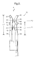
- Figure 2 is an end view of the female electrical terminal of Figure 1; and
- Figure 3 is an end view as shown in Figure 2 with a flat blade contact mated with the female electrical terminal.
-
- Referring to the drawings, the female
electrical terminal 10 in accordance with the present invention is for mating with aflat blade contact 12. Theterminal 10 comprises first, second, third andfourth arms second arms side 22 of theflat blade contact 12 and extend in the mating direction X. The third andfourth arms other side 24 of theflat blade contact 12 and also extend in the mating direction X. The first andsecond arms end free end fourth arms end free end first arm 14 is positioned opposed to thefourth arm 20, and thesecond arm 16 is positioned opposed to thethird arm 18. Each arm 14-20 has acontact area free end - In accordance with the present invention, the first and
third arms pivot end free end fourth arms pivot end free end contact areas third arms contact areas fourth arms contact areas third arms contact areas fourth arms blade contact 12, the four points of contact between the blade contact and thefemale terminal 10, are offset from one another when viewed from one side 22 (or the other side 24) of the blade contact. Such an arrangement substantially reduces the risk of theblade contact 12 pivoting relative to thefemale terminal 10. An additional advantage of the present invention is that the mating force is reduced (compared to the previously known arrangement described above), whereas the unmating force is substantially unchanged. - The
female terminal 10 is preferably formed in one piece by stamping and folding from sheet metallic material. Each arm 14-20 is preferably directly inwardly towards the opposed arm from itspivot end free end female terminal 10 and theblade contact 12, and provides a tapered opening for the female terminal to assist with alignment of the blade contact on initial mating. The second andfourth arms groove 50 formed therein which extends in the mating direction X to increase the resilience of the arm about itspivot end
Claims (6)
- A female electrical terminal (10) for mating with a flat blade contact (12) comprising first and second arms (14,16) positionable on one side (22) of the flat blade contact and extending in the mating direction (X); and third and fourth arms (18,20) positionable on the other side (24) of the flat blade contact and extending in the mating direction; wherein the first arm and the second arm are pivotally mounted at one end (26,28) on a first pivot axis (A); wherein the first and second arms have a free end (30,32) opposed to said one end; wherein the third arm and the fourth arm are pivotally mounted at one end (34,36) on a second pivot axis (B); wherein the third and fourth arms have a free end (38,40) opposed to said one end; wherein the first arm is positioned opposed to said fourth arm; wherein the second arm is positioned opposed to said third arm; wherein each arm has a contact area (42-48) formed adjacent the free end thereof directed towards the opposed arm; wherein the first and third arms have a first predetermined length (L1) between said one end and said free end thereof; wherein the second and fourth arms have a second predetermined length (L2) between said one end and said free end thereof, the second length being greater than said first length; wherein the contact areas of the first and third arms are substantially aligned on a first plane (P1) extending substantially perpendicular to the mating direction; and wherein the contact areas of the second and fourth arms are substantially aligned on a second plane (P2) which is substantially parallel to and offset from the first plane.
- A female electrical terminal as claimed in Claim 1, wherein each arm (14-20) is directed inwardly towards its opposed arm from its respective pivot axis (26,28,34,36) to its respective contact area (42-48).
- A female electrical terminal as claimed in Claim 2, wherein each arm (14-20) is directed outwardly away from its opposed arm from its respective contact area (42-48) to its respective free end (30,32,38,40).
- A female electrical terminal as claimed in any one of Claims 1 to 3, wherein the second and fourth arms (16,20) have a groove (50) formed therein which extends in the mating direction (X).
- A female electrical terminal as claimed in any one of Claims 1 to 4, wherein the first and second pivot axes (A,B) lie on a plane which is substantially parallel to the first and second planes (P1,P2).
- A female electrical terminal as claimed in any one of Claims 1 to 5, wherein the female terminal is formed in one-piece by stamping and folding from sheet metallic material.
Applications Claiming Priority (2)
| Application Number | Priority Date | Filing Date | Title |
|---|---|---|---|
| GB0110767 | 2001-05-02 | ||
| GB0110767A GB0110767D0 (en) | 2001-05-02 | 2001-05-02 | Female electrical terminal |
Publications (1)
| Publication Number | Publication Date |
|---|---|
| EP1255325A1 true EP1255325A1 (en) | 2002-11-06 |
Family
ID=9913893
Family Applications (1)
| Application Number | Title | Priority Date | Filing Date |
|---|---|---|---|
| EP02076493A Withdrawn EP1255325A1 (en) | 2001-05-02 | 2002-04-15 | Female electrical terminal |
Country Status (2)
| Country | Link |
|---|---|
| EP (1) | EP1255325A1 (en) |
| GB (1) | GB0110767D0 (en) |
Cited By (3)
| Publication number | Priority date | Publication date | Assignee | Title |
|---|---|---|---|---|
| GB2404793A (en) * | 2003-07-10 | 2005-02-09 | Bosch Gmbh Robert | Contact arrangement in the case of an electrical plug-in connection |
| WO2010147722A1 (en) * | 2009-06-19 | 2010-12-23 | Illinois Tool Works Inc. | Bifurcated electrical contact |
| JP2014232576A (en) * | 2013-05-28 | 2014-12-11 | 株式会社オートネットワーク技術研究所 | Multi-contact female terminal |
Citations (2)
| Publication number | Priority date | Publication date | Assignee | Title |
|---|---|---|---|---|
| US5088933A (en) * | 1989-09-08 | 1992-02-18 | Stocko Metallwarenfabriken Henkels Und Sohn Gmbh & Co. | Electrical contact element |
| EP0726615A2 (en) * | 1995-02-08 | 1996-08-14 | Osram Sylvania Inc. | Electrical contact |
-
2001
- 2001-05-02 GB GB0110767A patent/GB0110767D0/en not_active Ceased
-
2002
- 2002-04-15 EP EP02076493A patent/EP1255325A1/en not_active Withdrawn
Patent Citations (2)
| Publication number | Priority date | Publication date | Assignee | Title |
|---|---|---|---|---|
| US5088933A (en) * | 1989-09-08 | 1992-02-18 | Stocko Metallwarenfabriken Henkels Und Sohn Gmbh & Co. | Electrical contact element |
| EP0726615A2 (en) * | 1995-02-08 | 1996-08-14 | Osram Sylvania Inc. | Electrical contact |
Cited By (3)
| Publication number | Priority date | Publication date | Assignee | Title |
|---|---|---|---|---|
| GB2404793A (en) * | 2003-07-10 | 2005-02-09 | Bosch Gmbh Robert | Contact arrangement in the case of an electrical plug-in connection |
| WO2010147722A1 (en) * | 2009-06-19 | 2010-12-23 | Illinois Tool Works Inc. | Bifurcated electrical contact |
| JP2014232576A (en) * | 2013-05-28 | 2014-12-11 | 株式会社オートネットワーク技術研究所 | Multi-contact female terminal |
Also Published As
| Publication number | Publication date |
|---|---|
| GB0110767D0 (en) | 2001-06-27 |
Similar Documents
| Publication | Publication Date | Title |
|---|---|---|
| KR102923221B1 (en) | Electrical connection device for vehicle | |
| US5588884A (en) | Stamped and formed contacts for a power connector | |
| US8021200B2 (en) | Socket contact | |
| US6224432B1 (en) | Electrical contact with orthogonal contact arms and offset contact areas | |
| CN101093918B (en) | Negative terminal adaptor | |
| JP2609114B2 (en) | Contact socket | |
| EP0898792B1 (en) | Miniature card edge clip | |
| EP1276174A2 (en) | Electrical Connection System | |
| US5067916A (en) | Method for making an electrical contact | |
| US20100029146A1 (en) | Socket contact | |
| EP0966062B1 (en) | IDC Socket contact with high retention force | |
| CN1178400A (en) | Electrical connection terminal | |
| EP0726615A2 (en) | Electrical contact | |
| EP1746687A1 (en) | Dual beam receptacle connector | |
| US5611716A (en) | Electrical contact having improved secondary locking surfaces | |
| US6165003A (en) | Electrical connector with variable thickness insulation-piercing contact member | |
| US8622771B2 (en) | Electrical connector having versatile contact mating surfaces | |
| EP0701299B1 (en) | Female electrical terminal | |
| EP1089387A2 (en) | A modular female electrical terminal | |
| US6428366B1 (en) | Electrical terminal socket and method of fabricating same | |
| EP0937318B1 (en) | Female terminal with protective sleeve | |
| CN101431195B (en) | Electrical contact for land grid array socket assembly | |
| US10355386B2 (en) | Electrical connector with contact configured for surface mount | |
| EP0736930B1 (en) | Contact having an independently supported inner contact arm | |
| EP0967700A1 (en) | Electrical busbar with a terminal |
Legal Events
| Date | Code | Title | Description |
|---|---|---|---|
| PUAI | Public reference made under article 153(3) epc to a published international application that has entered the european phase |
Free format text: ORIGINAL CODE: 0009012 |
|
| AK | Designated contracting states |
Kind code of ref document: A1 Designated state(s): AT BE CH CY DE DK ES FI FR GB GR IE IT LI LU MC NL PT SE TR |
|
| AX | Request for extension of the european patent |
Free format text: AL;LT;LV;MK;RO;SI |
|
| 17P | Request for examination filed |
Effective date: 20030506 |
|
| AKX | Designation fees paid |
Designated state(s): DE FR IT |
|
| 17Q | First examination report despatched |
Effective date: 20030723 |
|
| APBN | Date of receipt of notice of appeal recorded |
Free format text: ORIGINAL CODE: EPIDOSNNOA2E |
|
| APBR | Date of receipt of statement of grounds of appeal recorded |
Free format text: ORIGINAL CODE: EPIDOSNNOA3E |
|
| APAA | Appeal reference recorded |
Free format text: ORIGINAL CODE: EPIDOS REFN |
|
| APAF | Appeal reference modified |
Free format text: ORIGINAL CODE: EPIDOSCREFNE |
|
| APBT | Appeal procedure closed |
Free format text: ORIGINAL CODE: EPIDOSNNOA9E |
|
| APBV | Interlocutory revision of appeal recorded |
Free format text: ORIGINAL CODE: EPIDOSNIRAPE |
|
| GRAP | Despatch of communication of intention to grant a patent |
Free format text: ORIGINAL CODE: EPIDOSNIGR1 |
|
| STAA | Information on the status of an ep patent application or granted ep patent |
Free format text: STATUS: THE APPLICATION IS DEEMED TO BE WITHDRAWN |
|
| 18D | Application deemed to be withdrawn |
Effective date: 20061006 |