EP1255267A1 - Relay for telecommunications network configuration - Google Patents
Relay for telecommunications network configuration Download PDFInfo
- Publication number
- EP1255267A1 EP1255267A1 EP02291094A EP02291094A EP1255267A1 EP 1255267 A1 EP1255267 A1 EP 1255267A1 EP 02291094 A EP02291094 A EP 02291094A EP 02291094 A EP02291094 A EP 02291094A EP 1255267 A1 EP1255267 A1 EP 1255267A1
- Authority
- EP
- European Patent Office
- Prior art keywords
- armature
- section
- magnetic
- relay
- relay according
- Prior art date
- Legal status (The legal status is an assumption and is not a legal conclusion. Google has not performed a legal analysis and makes no representation as to the accuracy of the status listed.)
- Withdrawn
Links
- 230000005291 magnetic effect Effects 0.000 claims abstract description 43
- 230000009471 action Effects 0.000 claims abstract description 3
- 230000004907 flux Effects 0.000 claims description 29
- 239000003302 ferromagnetic material Substances 0.000 claims description 7
- 230000005294 ferromagnetic effect Effects 0.000 claims description 6
- 239000004020 conductor Substances 0.000 claims description 2
- 239000000758 substrate Substances 0.000 description 13
- 239000000463 material Substances 0.000 description 4
- 229920006395 saturated elastomer Polymers 0.000 description 3
- 230000004913 activation Effects 0.000 description 2
- 238000002955 isolation Methods 0.000 description 2
- 230000035699 permeability Effects 0.000 description 2
- 238000005452 bending Methods 0.000 description 1
- 238000000151 deposition Methods 0.000 description 1
- 238000011835 investigation Methods 0.000 description 1
- 230000007246 mechanism Effects 0.000 description 1
- 238000000034 method Methods 0.000 description 1
- 238000007747 plating Methods 0.000 description 1
Images


Classifications
-
- H—ELECTRICITY
- H01—ELECTRIC ELEMENTS
- H01H—ELECTRIC SWITCHES; RELAYS; SELECTORS; EMERGENCY PROTECTIVE DEVICES
- H01H50/00—Details of electromagnetic relays
- H01H50/005—Details of electromagnetic relays using micromechanics
-
- H—ELECTRICITY
- H01—ELECTRIC ELEMENTS
- H01H—ELECTRIC SWITCHES; RELAYS; SELECTORS; EMERGENCY PROTECTIVE DEVICES
- H01H50/00—Details of electromagnetic relays
- H01H50/16—Magnetic circuit arrangements
- H01H50/36—Stationary parts of magnetic circuit, e.g. yoke
- H01H50/42—Auxiliary magnetic circuits, e.g. for maintaining armature in, or returning armature to, position of rest, for damping or accelerating movement
Definitions
- This invention relates to the structure of a magnetic relay. While the invention is suitable for use in miniaturized relays, it can also be used with larger relays.
- Unpublished patent application EP02290608.5 discloses a miniaturized relay formed integrally in a substrate such as a printed circuit board.
- the magnetic circuit is formed by depositing upper and lower sections of the magnetic path on the upper and lower surfaces of the substrate, and then connecting the upper and lower sections by holes through the substrate which are plated or filled with magnetizable (ferro-magnetic) material.
- the terms upper and lower are used arbitrarily for the purpose of establishing a reference, but the relay may be used in any orientation.
- the upper path also includes a cantilevered, resilient armature which is spaced above upper surface of the substrate so as to be able to make electrical contact with a contact pad.
- figure 1 shows an exploded view of an embodiment of this miniaturized relay having a magnetic path (6a, 6b) and activation coils installed on or in the support member 1.
- the activation coils are not shown in this figure for the sake of simplifying the view.
- the support member 1 is preferably a PCB and has vertical magnetic elements 4 and 5 formed in through holes 2 and 3, eg by plating through techniques.
- the magnetic path consists of a lower transverse member divided into two parts, 6a, 6b, by air or insulating gap 8, and an upper transverse member divided into two parts, 7a, 7b, which are vertically non-aligned and horizontally overlapping to provide a contact gap 9.
- the part 7a forms a contact pad
- the part 7b forms the flexible relay armature.
- the vertical gap is provided in this embodiment by extending the vertical pillar 5 to which the armature 7b is attached.
- An object of the invention is to provide a relay having a magnetically cantilevered armature allowing to have a quite low bending force without having saturation at the operating condition.
- the invention provides a relay having a magnetically cantilevered contact armature, said contact armature having a section with reduced cross section over a part of its length to provide a hinge action.
- the cantilevered armature is at least in part made of a ferro-magnetic material which has a sufficient cross section to retain a large portion of the operating magnetic flux without saturation.
- the reduced section Is located near the attachment point of the cantilever.
- suspended or cantilevered armature having a resiliently suspended movable contact zone associated with a magnetic shunt of sufficient cross-section to retain the operating magnetic flux, there being an air-gap at the end of the shunt proximate to the fixed contact point, the contact zone of the armature bridging the shunt air-gap, at least the bridging section including a ferro-magnetic material.
- the armature would carry a conductive path or be made of conductive material, but need not itself be ferro-magnetic.
- the section of ferro-magnetic material is of sufficient cross-section to reduce or avoid saturation at the operating flux. It is preferable that the thickness is sufficient to eliminate saturation at the operating flux.
- Nickle has both ferro-magnetic and electrical conductivity characteristics, but other types of materials may be selected separately for their magnetic and electrical characteristics in this embodiment.
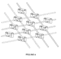
- Another object of the present invention is to provide an array of relays including a plurality of relays according to the invention, the magnetic circuit of each relay being formed on an upper and a lower surface of a PCB and being connected via a pair of through holes, the operating electrical coils being embedded in the PCB.
- the magnetic circuit includes a bottom portion 11 formed on the bottom surface of the substrate, two through-hole portions, 12 & 13 formed to connect the top and bottom surfaces of the substrate, a contact portion, 14 formed on the top surface of the substrate, and an armature 15 cantilevered above the substrate.
- An operating coil 18 passes through the magnetic path loop.
- the substrate may be for example, a multi-layer PCB to facilitate the inclusion of the operating coils in the substrate. It is also possible to include the bottom section of the magnetic path, 11 within the substrate.
- the armature 15 is made thin to reduce the force required to operate the armature. This results in a small cross-section which has a proportionately small saturation flux limit.
- the flux lines, 19, can be seen exiting the armature 15, indicating that the armature is saturated. As a consequence, the ampere turns to operate the armature is large if the armature saturates.
- Magnetic circuits can be analysed in a manner analogous to electrical circuits.
- F r ⁇
- A cross-sectional area
- B flux density
- r the reluctance of the magnetic circuit.
- Reluctance may be considered as analogous to resistance in an electric circuit, the flux is equivalent to the current , and the ampere turns equates to the voltage.
- a reluctance network can be analysed in the same manner as a resistance network.
- the units of reluctance are ampere-turns per weber.
- Figure 3 shows a first embodiment of the invention, in which the cross-section of the armature 27 is increased by increasing the thickness and/or the width. In this case, the thickness is shown as increased. This produces a proportionate increase in the flux carrying capacity of the armature.
- the force required to bend the armature to the contact position is increased due to the increase in the cross-section, particularly where the increase is in the same plane as the motion of the armature, ie, when the thickness is increased.
- the cross-section of the armature is reduced by a notch 22. This reduced cross-section portion functions as a hinge to reduce the force required to bend the armature to contact the contact pad 14.
- the notch is small, much of the flux which escapes from the beam at the notch is recaptured by the beam on the other side of the notch, the flux preferentially following the lower reluctance path rather than the air path.
- the beam thickness can be increased to avoid saturation at the operating flux.
- Figure 4 shows an alternative embodiment of the invention using a magnetic shunt, 30, to carry the magnetic flux to an air-gap proximate to the contact end of the armature.
- the shunt 30 may be formed on the top of the substrate at the same time as the contact pad is formed.
- the armature may be of similar dimensions to the armature of Figure 2, but the magnetic force produced is greater and is applied substantially at the end of the cantilever, increasing the turning moment because the flux is carried in the shunt to the shunt/contact air-gap, producing a larger flux density in this air-gap. Attraction forces are produced as the flux enters the end of the armature and as the flux exits the armature.
- the amount of flux which is "captured" by the end of the armature bridging the shunt/contact air gap depends on the relative reluctance of the path from the shunt to the end section of the armature added to the reluctance of the end of the armature plus the armature/contact air-gap compared with the shunt/contact air-gap 31.
- the shunt/contact air-gap should provide magnetic reluctance larger than the reluctance of the contact air-gap 16 plus the air-gap between the armature and the shunt 32 to ensure that a significant amount of the flux is diverted through the end of the armature rather than bridging the shunt/contact air-gap.
- the end of the armature is formed of a thickened ferro-magnetic section 33.
- the thickness is sufficient to avoid saturation at the operating flux.
- the increased cross-section produces an increase in the captured flux by reducing the reluctance of the path from the shunt to the contact via the armature end.
- the increase in the captured flux in turn increases the force applied to the beam.
- the rest of the armature can be left with a thinner section to retain flexibility.
- the armature attachment point of this embodiment can now be electrically and magnetically decoupled from the magnetic path.
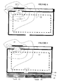
- Figure 5 shows a further embodiment of the invention including a magnetic sheet, 42, having alternate magnetic poles in strips corresponding to the layout of the relay array. Only the N-S pair under one relay is shown in the figure. Permanent magnets are high reluctance elements, so to improve the latching of the relay, we have added a sheet of magnetizable material, 41, between the magnetic circuit of the relay and the magnetic sheet 42. To ensure electrical isolation between the electrical contacts, an insulating sheet 40, can be included between the magnetizable sheet, 41, and the magnetic circuit of the relay. The magnetizable sheet 41 acts as a low reluctance path across the air gap 17.
- the North pole strip, 43, and the South pole strip, 44 are aligned to meet in the region f the air-gap 17.
- Figure 6 shows an array of relays including a plurality of relays according to the invention.
Landscapes
- Physics & Mathematics (AREA)
- Electromagnetism (AREA)
- Electromagnets (AREA)
Abstract
Description
Claims (12)
- A relay having a magnetically cantilevered armature, said contact armature having a section with reduced cross section over a part of its length to provide a hinge action.
- A relay according to claim 1 wherein said cantilevered armature is at least in part made of a ferro-magnetic material which has a sufficient cross section to retain a large portion of the operating magnetic flux without saturation.
- A relay according to any one of claims 1 or 2, wherein said section with reduced cross section is located proximate the attachment point of said cantilevered armature.
- A relay according to claim 1 having a magnetic path including a magnetic shunt of sufficient cross-section to retain the operating magnetic flux, there being a shunt/contact air-gap at the end of said shunt proximate to the contact point, and a section of a resilient armature bridging the shunt air-gap, at least the bridging section including a ferro-magnetic material.
- A relay according to claim 4 wherein said armature includes a conductive path.
- A relay according to any one of claims 4 or 5 wherein said armature includes conductive material
- A relay according to any one of claims 4 to 6 wherein said armature includes ferro-magnetic material.
- A relay according to any one of claims 4 to 7 wherein the section of ferro-magnetic material is of sufficient cross-section to reduce or avoid saturation at the operating flux.
- A relay according to any one of claims 1 to 8 wherein said armature includes a conductive path.
- A relay according to any one of claims 1 to 9 including an air-gap in the magnetic circuit and a permanent magnet bridging the air-gap.
- A relay according to claim 10, including a ferro-magnetic shunt providing a low reluctance path across said air-gap.
- An array of relays including a plurality of relays according to any one of the preceding claims, the magnetic circuit of each relay being formed on an upper and a lower surface of a PCB and being connected via a pair of through holes, the operating electrical coils being embedded in the PCB.
Applications Claiming Priority (4)
| Application Number | Priority Date | Filing Date | Title |
|---|---|---|---|
| AUPR475301 | 2001-05-04 | ||
| AUPR4753A AUPR475301A0 (en) | 2001-05-04 | 2001-05-04 | Micro-relay for telecommunications network configuration |
| AUPR580501 | 2001-06-20 | ||
| AUPR5805A AUPR580501A0 (en) | 2001-06-20 | 2001-06-20 | Micro-relay for telecommunications network configuration |
Publications (1)
| Publication Number | Publication Date |
|---|---|
| EP1255267A1 true EP1255267A1 (en) | 2002-11-06 |
Family
ID=25646671
Family Applications (1)
| Application Number | Title | Priority Date | Filing Date |
|---|---|---|---|
| EP02291094A Withdrawn EP1255267A1 (en) | 2001-05-04 | 2002-04-30 | Relay for telecommunications network configuration |
Country Status (1)
| Country | Link |
|---|---|
| EP (1) | EP1255267A1 (en) |
Citations (1)
| Publication number | Priority date | Publication date | Assignee | Title |
|---|---|---|---|---|
| US6094116A (en) * | 1996-08-01 | 2000-07-25 | California Institute Of Technology | Micro-electromechanical relays |
-
2002
- 2002-04-30 EP EP02291094A patent/EP1255267A1/en not_active Withdrawn
Patent Citations (1)
| Publication number | Priority date | Publication date | Assignee | Title |
|---|---|---|---|---|
| US6094116A (en) * | 1996-08-01 | 2000-07-25 | California Institute Of Technology | Micro-electromechanical relays |
Similar Documents
| Publication | Publication Date | Title |
|---|---|---|
| CN104221120B (en) | There is the relay of two switches that can reversely activate | |
| CN109659199B (en) | DC relay capable of extinguishing arc and resisting short-circuit current | |
| US6084281A (en) | Planar magnetic motor and magnetic microactuator comprising a motor of this type | |
| CN109659197B (en) | DC relay capable of extinguishing arc and resisting short-circuit current | |
| US6563409B2 (en) | Latching magnetic relay assembly | |
| US5216396A (en) | Switching relay | |
| JPH09198983A (en) | Small device | |
| KR20100029782A (en) | Microrelay | |
| Taylor et al. | Integrated magnetic microrelays: normally open, normally closed, and multi-pole devices | |
| JP5427492B2 (en) | Electromagnetic relay | |
| CN109830404B (en) | DC relay with arc extinguishing and short-circuit current resisting functions | |
| EP1255267A1 (en) | Relay for telecommunications network configuration | |
| US20020163409A1 (en) | Telecommunication relay array for DSL network configuration | |
| US3196232A (en) | Reed relay | |
| US20030179058A1 (en) | System and method for routing input signals using single pole single throw and single pole double throw latching micro-magnetic switches | |
| AU2002300765A1 (en) | Micro-relay for telecommunications network configuration | |
| CA2182931C (en) | Switching field | |
| CN110867348B (en) | A relay with high short circuit resistance | |
| JPS62217512A (en) | Mercury switch | |
| GB2118368A (en) | Electric power switch with slotted commutation end plate | |
| US3001048A (en) | Miniature modular relay | |
| JPS58216321A (en) | Armature rotating electromagnetic relay | |
| CN210692440U (en) | High-short-circuit-resistance relay | |
| JPH05174691A (en) | Seesaw balance type polarized relay | |
| CA1234851A (en) | Monostable type relay |
Legal Events
| Date | Code | Title | Description |
|---|---|---|---|
| PUAI | Public reference made under article 153(3) epc to a published international application that has entered the european phase |
Free format text: ORIGINAL CODE: 0009012 |
|
| AK | Designated contracting states |
Kind code of ref document: A1 Designated state(s): AT BE CH CY DE DK ES FI FR GB GR IE IT LI LU MC NL PT SE TR |
|
| AX | Request for extension of the european patent |
Free format text: AL;LT;LV;MK;RO;SI |
|
| 17P | Request for examination filed |
Effective date: 20030325 |
|
| AKX | Designation fees paid |
Designated state(s): AT BE CH CY DE DK ES FI FR GB GR IE IT LI LU MC NL PT SE TR |
|
| AXX | Extension fees paid |
Extension state: LV Payment date: 20030506 Extension state: MK Payment date: 20030506 Extension state: LT Payment date: 20030506 Extension state: AL Payment date: 20030506 Extension state: SI Payment date: 20030506 Extension state: RO Payment date: 20030506 |
|
| RAP1 | Party data changed (applicant data changed or rights of an application transferred) |
Owner name: ALCATEL LUCENT |
|
| STAA | Information on the status of an ep patent application or granted ep patent |
Free format text: STATUS: THE APPLICATION IS DEEMED TO BE WITHDRAWN |
|
| 18D | Application deemed to be withdrawn |
Effective date: 20071101 |