EP1255102A2 - Infrared detection of standing waves - Google Patents
Infrared detection of standing waves Download PDFInfo
- Publication number
- EP1255102A2 EP1255102A2 EP02100404A EP02100404A EP1255102A2 EP 1255102 A2 EP1255102 A2 EP 1255102A2 EP 02100404 A EP02100404 A EP 02100404A EP 02100404 A EP02100404 A EP 02100404A EP 1255102 A2 EP1255102 A2 EP 1255102A2
- Authority
- EP
- European Patent Office
- Prior art keywords
- tire
- mph
- standing waves
- thermal
- standing
- Prior art date
- Legal status (The legal status is an assumption and is not a legal conclusion. Google has not performed a legal analysis and makes no representation as to the accuracy of the status listed.)
- Withdrawn
Links
Images

Classifications
-
- G—PHYSICS
- G01—MEASURING; TESTING
- G01M—TESTING STATIC OR DYNAMIC BALANCE OF MACHINES OR STRUCTURES; TESTING OF STRUCTURES OR APPARATUS, NOT OTHERWISE PROVIDED FOR
- G01M17/00—Testing of vehicles
- G01M17/007—Wheeled or endless-tracked vehicles
- G01M17/02—Tyres
- G01M17/027—Tyres using light, e.g. infrared, ultraviolet or holographic techniques
Definitions
- the invention relates to the use of a thermal detecting device to detect standing waves in a tire.
- Standing waves are sinusoidal in nature, and are an indication of the expenditure of energy and stresses placed on a tire being focused on certain locations in the tire. Standing waves develop at certain speeds or inflations as the tire is tested and may fluctuate between severe and non-severe amplitudes depending on the testing speeds.
- the method to detect standing waves comprised the use of moire images, i.e., images created using interferometry.
- the detection of the standing waves, the speed at which they occur, and their severity, are information used by the tire designer in modifying his design to reduce or eliminate the problem.
- Standing waves may cause a tire to fail prematurely.
- shadow moire testing to a certain extent, will always have value, there is the need in the art for alternative testing which may be less expensive and, if possible, produces data that may be more easily analyzed.
- Other methods may at least supplement the data that can be obtained from shadow moire images.
- a method for detecting standing waves in a rotating tire comprises the steps of (a) using a thermal detecting device to obtain a temperature profile of a rotating tire, and (b) analyzing thermal patterns in the data.
- the method may include using hardware and software for automating data capture and analysis.
- a high speed infrared camera was used for obtaining thermal images. It has been found that a thermal difference between the valley and the peak of a standing wave can be detected at 40 mph to 80 mph (64 to 128 km/h).
- the purpose of the invention is to use a thermal detecting device, in the illustrated embodiment high speed infrared thermography to detect and analyze the formation of standing waves in a tire before they can be visually seen.
- the standing waves appear as bumps or bulges on the tire.
- the sidewall constantly flexes as the tread moves in and out of the footprint of the tire.
- the constant flexing of the rubber in the tire creates heat.
- the zero crossing of the sinusoidal flexing appears different from the flexing occurring at the positive and negative excursions of the sign wave, creating a thermal difference between the areas where the standing waves occur and the rest of the tire sidewall. It has been found in accordance with the present invention that the difference in the heat dissipation in these areas can be detected by a high speed infrared camera.
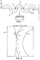
- Fig. 1 it is theorized that in a tire, maximum flexing takes place in the peaks 10 and valleys 12 of a standing wave (SWV).
- SWV standing wave
- the camera view in Fig. 1 illustrates what the IR camera would see when it is perpendicular to a sidewall 18 (Fig. 2) of a tire.
- the zero point 14 of the sinusoidal wave, in relative terms, is motionless.
- the peaks and valleys will therefore show up in thermal imaging as the hot spots on a tire sidewall.
- the standing waves will show up as cold spots, or dark spots in the thermal imaging. Further work needs to be done to confirm this theory.
- Preliminary work has shown a thermal difference that can be used to detect standing waves, but the nature of the thermal difference has not yet been fully characterized.
- the tire imaged was rotated against a 60 inch (1,52 m) high speed test wheel 20 with a load of 1085 pounds (492 kg) at an inflation of 41 pounds per square inch (psi) (282 kPa).
- the tire tested was size P215/60R14. The test was carried out by stepping up the speed of the tire in increments.
- the tire was run at 50 mph (80 km/h) for 10 minutes, 80 mph (129 km/h) for 30 seconds, 85 mph (137 km/h) for 30 seconds, 90 mph (145 km/h) for 30 seconds, 95 mph (153 km/h) for 30 seconds, 97 mph (156 km/h) for 30 seconds, 99 mph (159 km/h) for 30 seconds, 101 mph (163 km/h) for 30 seconds, 103 mph (166 km/h) for 30 seconds, and 105 mph (169 km/h) for 30 seconds.
- the standing waves 16 generally develop at regular intervals.
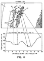
- the image obtained at the end of the 50 mph (80 km/h) step was enlarged in Fig. 3.
- a similar enlargement is provided for the image obtained at 105 mph (169 km/h) in Fig. 4.
- standing waves When standing waves are formed, they appear to maintain a stationary position in the tire, and as the speed increases, additional waves are formed in between existing waves, while the original standing waves maintain their position.
- the standing waves at 50 mph (80 km/h) and the standing waves at 105 mph (169 km/h) are in substantially the same position in the tire, however, in the 105 mph (169 km/h) image, two cooler areas 14 are present in the area where one cooler area was present at 50 mph (80 km/h). It is theorized that the peak 10 of the standing wave is present between the two zero points 14 on the wave, and has a thermal gradient similar to the thermal gradient of the rest of the tire sidewall 18.
- the lettering 22 obstructs what may be the second standing wave in the image made at 50 mph (80 km/h), whereas the effect of the lettering on the imaging at 105 mph (169 km/h) is minimized by the increased temperature obtained at higher speeds.
- the image can be broken down into pixels 24, and the thermal properties of the pixels can be analyzed to accurately map the thermal properties of the standing wave in the sidewall of the tire.
- the temperature scale was fixed across the images to aid in visualizing the heating up of the tire as the speed increased.
- the test of the tire was continued up to 105 mph (169 km/h) so that data obtained by infrared thermography could be compared with shadow moire data, in order to confirm that the standing waves detected by infrared thermography coincide with standing waves detected by Shadow Moire techniques.
- the temperature differential between the cooler areas and the hotter areas is 1°F (0,55°C) in each case.
- the invention can be used as a tool by the tire designer to make decisions on design changes based on the speed at which the waves are detected in order to reduce standing wave formations. Detecting the standing waves at lower speed steps gives the tire designer a more accurate view of the tire properties.
Landscapes
- Physics & Mathematics (AREA)
- General Physics & Mathematics (AREA)
- Investigating Or Analyzing Materials Using Thermal Means (AREA)
- Length Measuring Devices By Optical Means (AREA)
Abstract
Description
Claims (4)
- A method for detecting standing waves in a rotating tire comprising the steps of using a thermal detecting device to obtain a temperature profile of a rotating tire, and analyzing thermal data obtained.
- The method of claim 1 which comprises the further step of using hardware and software for automating data capture and analysis.
- The method of claim 1 comprising the step of using a high speed infrared camera for obtaining thermal images.
- The method of claim 1 comprising the step of detecting a thermal difference between the valley and the peak of a standing wave at 40 mph to 80 mph (64 to 129 km/h).
Applications Claiming Priority (2)
| Application Number | Priority Date | Filing Date | Title |
|---|---|---|---|
| US848629 | 2001-05-03 | ||
| US09/848,629 US6644106B2 (en) | 2001-05-03 | 2001-05-03 | Thermal detection of standing waves |
Publications (2)
| Publication Number | Publication Date |
|---|---|
| EP1255102A2 true EP1255102A2 (en) | 2002-11-06 |
| EP1255102A3 EP1255102A3 (en) | 2002-12-18 |
Family
ID=25303844
Family Applications (1)
| Application Number | Title | Priority Date | Filing Date |
|---|---|---|---|
| EP02100404A Withdrawn EP1255102A3 (en) | 2001-05-03 | 2002-04-24 | Infrared detection of standing waves |
Country Status (3)
| Country | Link |
|---|---|
| US (1) | US6644106B2 (en) |
| EP (1) | EP1255102A3 (en) |
| BR (1) | BR0201411A (en) |
Cited By (1)
| Publication number | Priority date | Publication date | Assignee | Title |
|---|---|---|---|---|
| EP2583247A4 (en) * | 2010-06-15 | 2017-12-06 | Compagnie Générale des Etablissements Michelin | Tire surface anomaly detection |
Family Cites Families (9)
| Publication number | Priority date | Publication date | Assignee | Title |
|---|---|---|---|---|
| US4348898A (en) * | 1980-02-11 | 1982-09-14 | The Goodyear Tire & Rubber Company | Direct reading temperature and circumferential tire monitor |
| US4875176A (en) * | 1987-10-22 | 1989-10-17 | Curtis L. Harsch | Method and apparatus for measuring surface temperatures |
| US5095744A (en) * | 1989-04-12 | 1992-03-17 | Vulcan Equipment Company | Ultrasonic tire testing method and apparatus |
| US5297424A (en) * | 1990-03-07 | 1994-03-29 | Monroe Auto Equipment Company | Telemetry system for tire pressure and temperature sensing |
| US5216372A (en) * | 1991-07-29 | 1993-06-01 | Colorado State University Research Foundation | Microwave steel belt location sensor for tires |
| EP0788296B1 (en) * | 1994-04-07 | 2005-03-23 | Matsushita Electric Industrial Co., Ltd. | High-frequency heating device |
| US6089750A (en) * | 1997-09-30 | 2000-07-18 | Sumitomo Electric Industries, Ltd. | Noncontact temperature distribution measuring apparatus |
| US6226933B1 (en) * | 1999-08-10 | 2001-05-08 | Robert S. Nelson | Apparatus and method for enhancing the survivability of exposed structures |
| US6438255B1 (en) * | 2000-04-14 | 2002-08-20 | Stress Photonics, Inc. | Transient thermal marking of objects |
-
2001
- 2001-05-03 US US09/848,629 patent/US6644106B2/en not_active Expired - Fee Related
-
2002
- 2002-04-24 BR BR0201411-4A patent/BR0201411A/en not_active IP Right Cessation
- 2002-04-24 EP EP02100404A patent/EP1255102A3/en not_active Withdrawn
Cited By (1)
| Publication number | Priority date | Publication date | Assignee | Title |
|---|---|---|---|---|
| EP2583247A4 (en) * | 2010-06-15 | 2017-12-06 | Compagnie Générale des Etablissements Michelin | Tire surface anomaly detection |
Also Published As
| Publication number | Publication date |
|---|---|
| US6644106B2 (en) | 2003-11-11 |
| EP1255102A3 (en) | 2002-12-18 |
| US20020162398A1 (en) | 2002-11-07 |
| BR0201411A (en) | 2003-06-10 |
Similar Documents
| Publication | Publication Date | Title |
|---|---|---|
| CN115751203B (en) | A natural gas pipeline leakage monitoring system based on infrared thermal imager | |
| Cha et al. | Vision-based detection of loosened bolts using the Hough transform and support vector machines | |
| Kapela et al. | Asphalt surfaced pavement cracks detection based on histograms of oriented gradients | |
| CN101939191B (en) | Object Detection and Recognition System | |
| US20230152150A1 (en) | Road surface conditions detection by distributed optic fiber system | |
| IT201800004673A1 (en) | PROCEDURE AND SYSTEM FOR DETECTION OF DEFECTS IN A TIRE | |
| CN105158257A (en) | Sliding plate measurement method and device | |
| CN119915623A (en) | A performance testing method and device for polyurethane material | |
| CN104897269A (en) | Overhead wire vibration frequency measuring system based on linear scanning imaging | |
| CN111882664A (en) | Multi-window accumulated difference crack extraction method | |
| CN112488995B (en) | Intelligent damage assessment method and system for automated train maintenance | |
| Gao et al. | A multispectral vision-based machine learning framework for non-contact vehicle weigh-in-motion | |
| Ho et al. | Automatic image recognition of pavement distress for improving pavement inspection | |
| Wang et al. | Research on monitoring road surface anomalies using an IoT-based automatic detection system: Case study in Taiwan | |
| US6644106B2 (en) | Thermal detection of standing waves | |
| CN117809072A (en) | A subway station steel pipe column detection method based on infrared sensor | |
| CN112233683A (en) | Abnormal noise detection method and detection system for automobile electric rearview mirror | |
| CN112526154B (en) | Unmarked measuring method for motion of circular template matching rotating structure under computer vision | |
| CN120213645A (en) | A method and device for detecting tensile properties of fasteners | |
| CN120375315A (en) | Automatic pavement crack detection system based on machine learning | |
| Xu et al. | Nondestructive testing of bridge stay cable surface defects based on computer vision | |
| Kotchon et al. | Damage detection in tires using image-based strain measurements | |
| CN119068373A (en) | A pipeline monitoring and maintenance method based on drones | |
| CN111695272B (en) | Rivet type contact surface roughness characterization method based on rotation fusion | |
| CN111247412B (en) | Tire Test Device |
Legal Events
| Date | Code | Title | Description |
|---|---|---|---|
| PUAI | Public reference made under article 153(3) epc to a published international application that has entered the european phase |
Free format text: ORIGINAL CODE: 0009012 |
|
| PUAL | Search report despatched |
Free format text: ORIGINAL CODE: 0009013 |
|
| AK | Designated contracting states |
Kind code of ref document: A2 Designated state(s): AT BE CH CY DE DK ES FI FR GB GR IE IT LI LU MC NL PT SE TR |
|
| AX | Request for extension of the european patent |
Free format text: AL;LT;LV;MK;RO;SI |
|
| AK | Designated contracting states |
Kind code of ref document: A3 Designated state(s): AT BE CH CY DE DK ES FI FR GB GR IE IT LI LU MC NL PT SE TR |
|
| AX | Request for extension of the european patent |
Free format text: AL;LT;LV;MK;RO;SI |
|
| RIC1 | Information provided on ipc code assigned before grant |
Free format text: 7G 01M 17/007 A, 7G 01M 17/02 B |
|
| 17P | Request for examination filed |
Effective date: 20030618 |
|
| AKX | Designation fees paid |
Designated state(s): DE FR GB IT |
|
| STAA | Information on the status of an ep patent application or granted ep patent |
Free format text: STATUS: THE APPLICATION HAS BEEN WITHDRAWN |
|
| 18W | Application withdrawn |
Effective date: 20071030 |