EP1255055A1 - Drum brake and wear sensor therefor - Google Patents
Drum brake and wear sensor therefor Download PDFInfo
- Publication number
- EP1255055A1 EP1255055A1 EP02076268A EP02076268A EP1255055A1 EP 1255055 A1 EP1255055 A1 EP 1255055A1 EP 02076268 A EP02076268 A EP 02076268A EP 02076268 A EP02076268 A EP 02076268A EP 1255055 A1 EP1255055 A1 EP 1255055A1
- Authority
- EP
- European Patent Office
- Prior art keywords
- drum
- brake
- wear sensor
- lining material
- friction lining
- Prior art date
- Legal status (The legal status is an assumption and is not a legal conclusion. Google has not performed a legal analysis and makes no representation as to the accuracy of the status listed.)
- Withdrawn
Links
Images
Classifications
-
- F—MECHANICAL ENGINEERING; LIGHTING; HEATING; WEAPONS; BLASTING
- F16—ENGINEERING ELEMENTS AND UNITS; GENERAL MEASURES FOR PRODUCING AND MAINTAINING EFFECTIVE FUNCTIONING OF MACHINES OR INSTALLATIONS; THERMAL INSULATION IN GENERAL
- F16D—COUPLINGS FOR TRANSMITTING ROTATION; CLUTCHES; BRAKES
- F16D66/00—Arrangements for monitoring working conditions, e.g. wear, temperature
- F16D66/02—Apparatus for indicating wear
-
- F—MECHANICAL ENGINEERING; LIGHTING; HEATING; WEAPONS; BLASTING
- F16—ENGINEERING ELEMENTS AND UNITS; GENERAL MEASURES FOR PRODUCING AND MAINTAINING EFFECTIVE FUNCTIONING OF MACHINES OR INSTALLATIONS; THERMAL INSULATION IN GENERAL
- F16D—COUPLINGS FOR TRANSMITTING ROTATION; CLUTCHES; BRAKES
- F16D51/00—Brakes with outwardly-movable braking members co-operating with the inner surface of a drum or the like
- F16D51/16—Brakes with outwardly-movable braking members co-operating with the inner surface of a drum or the like shaped as brake-shoes pivoted on a fixed or nearly-fixed axis
- F16D51/18—Brakes with outwardly-movable braking members co-operating with the inner surface of a drum or the like shaped as brake-shoes pivoted on a fixed or nearly-fixed axis with two brake-shoes
- F16D51/20—Brakes with outwardly-movable braking members co-operating with the inner surface of a drum or the like shaped as brake-shoes pivoted on a fixed or nearly-fixed axis with two brake-shoes extending in opposite directions from their pivots
Definitions
- the present invention relates to a drum brake for a motor vehicle, and in particular to a wear sensor for a drum brake.
- a drum brake consists of a drum, first and second brake shoes; and an actuator for moving the friction lining material on each brake shoe into engagement with the drum. It is known to provide an electric wear sensor which provides a signal when the brake shoes are worn and need replacing. Electric wear sensors are expensive. GB-A-2103737 and WO-A-95/03500 describe audible wear sensors for disc brakes.
- a drum brake in accordance with the present invention comprises a drum; a first brake shoe which is pivotally mounted at one end thereof and having friction lining material thereon; a second brake shoe which is pivotally mounted at one end thereof and having friction lining material thereon; spring means biasing the friction material of each brake shoe away from the drum; at least one actuator engaging the other end of each brake shoe for moving the friction lining material of each brake shoe into contact with the drum on actuation thereof against the bias of the spring means; and a wear sensor mounted on one of the brake shoes in a position circumferentially spaced from the friction lining material thereon, and having a free end positioned adjacent the drum; wherein the free end of the wear sensor engages the drum to produce an audible signal solely when the or each actuator is actuated, and when the radial height of the friction lining material is at or below a predetermined minimum.
- the present invention provides a wear sensor for a drum brake which is cheap.
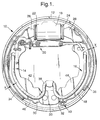
- a drum brake 10 in accordance with the present invention is shown which comprises a drum 12, first and second brake shoes 14, 16 respectively; a hydraulic actuator 18; a shoe spring 38; and a wear sensor 40.
- the hydraulic actuator 18 is fluidly connected to the braking system of a motor vehicle (not shown) and comprises a pair of pistons 22, 24. Each piston 22,24 engages one end 26,28 respectively of one of the brake shoes 14,16 respectively.
- Each brake shoe 14,16 is pivotally mounted at its other end 30,32 respectively in contact with an abutment 33.
- Each brake shoe 14,16 comprises a plate member 42,44 respectively with an integral rim 46,48 respectively.
- Friction lining material 34,36 is carried on the rim 46,48 respectively of each brake shoe 14,16 respectively and directed towards the drum 12.
- the friction lining material 34,36 has a radial height Y which varies between a maximum value when the brake shoes 14,16 are new, and a predetermined minimum value when the brake shoes are worn and need replacing.
- the shoe spring 38 retains the brake shoes 14,16 in engagement with the hydraulic actuator 18 and the abutment 33.
- the shoe spring 38 biases the friction lining material 34,36 out of engagement with the drum 12 with a gap X therebetween.
- the drum brake 10 may include a wear adjuster 20 (for example, as described in GB-A-2256463) for maintaining the gap X at a predetermined value.
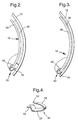
- the wear sensor 40 ( Figure 4) is formed from bent sheet metal and is substantially U-shaped or V-shaped. Other shapes for the wear sensor 40 may be used.
- the free end 50 of one arm 52 of the wear sensor 40 is secured to the rim 48 of the second brake shoe 16 (preferably at one end of the shoe) in any suitable manner, such as screwing, riveting or welding.
- the wear sensor 40 may be mounted elsewhere on the second brake shoe 16.
- the wear sensor 40 is mounted on the second brake shoe 16 at a position which is circumferentially spaced from the friction lining material 36.
- the free end 54 of the other arm 56 of the wear sensor 40 extends to a position adjacent to the drum 12.
- the wear sensor 40 may be mounted on the first brake shoe 14, or wear sensors may be mounted on each brake shoe.
- the above described embodiment uses a single actuator 18 for actuating both brake shoes 14,16.
- the present invention also includes a drum brake having a separate actuator for each brake shoe.
- a hydraulic actuator has been described above, the present invention is also applicable to drum brakes having other types of actuator, such as an electric actuator. Further, the present invention applies to drum brakes in which the brake shoes move radially outwards to engage the drum (as described above), and to drum brakes in which the brake shoes move radially inwards to engage the drum.
- the present invention provides a wear sensor for a drum brake which is cheap to produce and is easy to install.
Landscapes
- Engineering & Computer Science (AREA)
- General Engineering & Computer Science (AREA)
- Mechanical Engineering (AREA)
- Braking Arrangements (AREA)
Abstract
A drum brake (10) comprising a drum (12); a first brake shoe
(14) which is pivotally mounted at one end (30) thereof and having friction
lining material (34) thereon; a second brake shoe (16) which is pivotally
mounted at one end (32) thereof and having friction lining material (36) thereon;
spring means (38) biasing the friction material of each brake shoe away from the
drum; at least one actuator (18) engaging the other end of each brake shoe for
moving the friction lining material of each brake shoe into contact with the
drum on actuation thereof against the bias of the spring means; and a wear
sensor (40) mounted on one of the brake shoes in a position circumferentially
spaced from the friction lining material thereon, and having a free end (54)
positioned adjacent the drum; wherein the free end of the wear sensor engages
the drum to produce an audible signal solely when the or each actuator is
actuated, and when the radial height of the friction lining material is at or below
a predetermined minimum. Provides a cheap wear sensor for a drum brake.
Description
- The present invention relates to a drum brake for a motor vehicle, and in particular to a wear sensor for a drum brake.
- A drum brake consists of a drum, first and second brake shoes; and an actuator for moving the friction lining material on each brake shoe into engagement with the drum. It is known to provide an electric wear sensor which provides a signal when the brake shoes are worn and need replacing. Electric wear sensors are expensive. GB-A-2103737 and WO-A-95/03500 describe audible wear sensors for disc brakes.
- It is an object of the present invention to provide an audible wear sensor for a drum brake.
- A drum brake in accordance with the present invention comprises a drum; a first brake shoe which is pivotally mounted at one end thereof and having friction lining material thereon; a second brake shoe which is pivotally mounted at one end thereof and having friction lining material thereon; spring means biasing the friction material of each brake shoe away from the drum; at least one actuator engaging the other end of each brake shoe for moving the friction lining material of each brake shoe into contact with the drum on actuation thereof against the bias of the spring means; and a wear sensor mounted on one of the brake shoes in a position circumferentially spaced from the friction lining material thereon, and having a free end positioned adjacent the drum; wherein the free end of the wear sensor engages the drum to produce an audible signal solely when the or each actuator is actuated, and when the radial height of the friction lining material is at or below a predetermined minimum.
- The present invention provides a wear sensor for a drum brake which is cheap.
- The present invention will now be described, by way of example, with reference to the accompanying drawings, in which:-
- Figure 1 is a side view, partly in cross-section, of a drum brake in accordance with the present invention;
- Figure 2 is a side view of a portion of the drum and one of the brake shoes with the wear sensor of the drum brake of Figure 1, when actuated, and when the brake shoe is not worn;
- Figure 3 is a side view of a portion of the drum and one of the brake shoes with the wear sensor of the drum brake of Figure 1, when actuated, and when the brake shoe is worn; and
- Figure 4 is an enlarged perspective view of the wear sensor of the drum brake of Figure 1.
-
- Referring to the drawings, a
drum brake 10 in accordance with the present invention is shown which comprises adrum 12, first andsecond brake shoes hydraulic actuator 18; ashoe spring 38; and awear sensor 40. Thehydraulic actuator 18 is fluidly connected to the braking system of a motor vehicle (not shown) and comprises a pair ofpistons piston end brake shoes brake shoe other end abutment 33. Eachbrake shoe plate member integral rim Friction lining material rim brake shoe drum 12. Thefriction lining material brake shoes - The
shoe spring 38 retains thebrake shoes hydraulic actuator 18 and theabutment 33. Theshoe spring 38 biases thefriction lining material drum 12 with a gap X therebetween. Thedrum brake 10 may include a wear adjuster 20 (for example, as described in GB-A-2256463) for maintaining the gap X at a predetermined value. - On actuation of the
hydraulic actuator 18, thepistons shoe spring 38 to close the gap X. Thefriction lining material brake shoe drum 12 to provide braking. On release, theshoe spring 38 moves thebrake shoes - The wear sensor 40 (Figure 4) is formed from bent sheet metal and is substantially U-shaped or V-shaped. Other shapes for the
wear sensor 40 may be used. Thefree end 50 of onearm 52 of thewear sensor 40 is secured to therim 48 of the second brake shoe 16 (preferably at one end of the shoe) in any suitable manner, such as screwing, riveting or welding. Thewear sensor 40 may be mounted elsewhere on thesecond brake shoe 16. Thewear sensor 40 is mounted on thesecond brake shoe 16 at a position which is circumferentially spaced from thefriction lining material 36. Thefree end 54 of theother arm 56 of thewear sensor 40 extends to a position adjacent to thedrum 12. As an alternative, thewear sensor 40 may be mounted on thefirst brake shoe 14, or wear sensors may be mounted on each brake shoe. - In the rest position of the drum brake 10 (Figure 1), the
free end 54 of theother arm 56 of thewear sensor 40 is spaced from thedrum 12. In the actuated position of thedrum brake 10, and when the radial height of thefriction lining material free end 54 of theother arm 56 of thewear sensor 40 is spaced from thedrum 12. In the actuated position of thedrum brake 10, and when the radial height of thefriction lining material free end 54 of theother arm 56 of thewear sensor 40 engages thedrum 12. Due to the engagement with thedrum 12, theother arm 56 of thewear sensor 40 acts like a vibrating reed and generates a distinct and audible noise. Such a noise is an indication that thebrake shoes - The above described embodiment uses a
single actuator 18 for actuating bothbrake shoes - The present invention provides a wear sensor for a drum brake which is cheap to produce and is easy to install.
Claims (4)
- A drum brake (10) comprising a drum (12); a first brake shoe (14) which is pivotally mounted at one end (30) thereof and having friction lining material (34) thereon; a second brake shoe (16) which is pivotally mounted at one end (32) thereof and having friction lining material (36) thereon; spring means (38) biasing the friction material of each brake shoe away from the drum; at least one actuator (18) engaging the other end of each brake shoe for moving the friction lining material of each brake shoe into contact with the drum on actuation thereof against the bias of the spring means; and a wear sensor (40) mounted on one of the brake shoes in a position circumferentially spaced from the friction lining material thereon, and having a free end (54) positioned adjacent the drum; wherein the free end of the wear sensor engages the drum to produce an audible signal solely when the or each actuator is actuated, and when the radial height of the friction lining material is at or below a predetermined minimum.
- A drum brake as claimed in Claim 1, wherein the wear sensor (40) is formed from bent sheet metal.
- A drum brake as claimed in Claim 1 or Claim 2, wherein the wear sensor (40) is substantially U-shaped or V-shaped; and wherein the free end (54) is at the end of one of the arms (56).
- A drum brake as claimed in any one of Claims 1 to 3, wherein the brake shoes (14,16) include a rim (46,48) on which the friction lining material (34,36) is mounted; and wherein the wear sensor (40) is mounted on the rim of one of the brake shoes at one end thereof.
Applications Claiming Priority (2)
| Application Number | Priority Date | Filing Date | Title |
|---|---|---|---|
| FR0105581 | 2001-04-25 | ||
| FR0105581A FR2824118A1 (en) | 2001-04-25 | 2001-04-25 | DRUM BRAKE AND WEAR DETECTOR FOR SUCH A BRAKE |
Publications (1)
| Publication Number | Publication Date |
|---|---|
| EP1255055A1 true EP1255055A1 (en) | 2002-11-06 |
Family
ID=8862687
Family Applications (1)
| Application Number | Title | Priority Date | Filing Date |
|---|---|---|---|
| EP02076268A Withdrawn EP1255055A1 (en) | 2001-04-25 | 2002-04-03 | Drum brake and wear sensor therefor |
Country Status (3)
| Country | Link |
|---|---|
| US (1) | US20020167402A1 (en) |
| EP (1) | EP1255055A1 (en) |
| FR (1) | FR2824118A1 (en) |
Cited By (4)
| Publication number | Priority date | Publication date | Assignee | Title |
|---|---|---|---|---|
| CN110077984A (en) * | 2019-04-18 | 2019-08-02 | 宁波市凹凸重工有限公司 | A kind of system and method for crane brake safety monitoring control |
| CN111536173A (en) * | 2020-05-06 | 2020-08-14 | 一汽解放汽车有限公司 | Brake shoe mechanism and brake device |
| CN112483567A (en) * | 2020-11-17 | 2021-03-12 | 浙江农林大学 | Brake pad thickness detection device for drum brake and detection method thereof |
| CN112797093A (en) * | 2021-01-29 | 2021-05-14 | 徐州九阳机械制造有限公司 | Brake drum braking device for engineering truck |
Families Citing this family (3)
| Publication number | Priority date | Publication date | Assignee | Title |
|---|---|---|---|---|
| US8181752B2 (en) * | 2003-08-20 | 2012-05-22 | Arvinmeritor Technology, Llc | Brake overstroke indication system |
| DE602004015613D1 (en) * | 2004-10-25 | 2008-09-18 | Meritor Heavy Vehicle Braking | Brake lever assembly for motor vehicle and method of assembly |
| US9291213B2 (en) * | 2010-08-17 | 2016-03-22 | Borg Warner Inc. | Pneumatic clutch with improved friction member |
Citations (7)
| Publication number | Priority date | Publication date | Assignee | Title |
|---|---|---|---|---|
| US3975706A (en) * | 1973-05-04 | 1976-08-17 | Kabushiki Kaisha Toyota Chuo Kenkyusho | Abnormality-detecting device in a brake system |
| US4085826A (en) * | 1976-12-13 | 1978-04-25 | The Bendix Corporation | Brake wear indicator |
| US4250978A (en) * | 1979-07-02 | 1981-02-17 | The Bendix Corporation | Lining wear sensor |
| US4498559A (en) * | 1981-10-27 | 1985-02-12 | Toyota Jidosha Kogyo Kabushiki Kaisha | Friction-pad wear-limit warning device for disc brakes |
| EP0596761A1 (en) * | 1992-11-04 | 1994-05-11 | Alliedsignal Materiaux De Friction | Brake pad carrier of a disc brake with noise generating wear indicator |
| JPH10299799A (en) * | 1997-04-24 | 1998-11-10 | Hitachi Chem Co Ltd | Disc pad |
| US5893434A (en) * | 1997-04-17 | 1999-04-13 | Meritor Heavy Vehicle Systems, Llc | Lining wear indicator for a drum brake |
Family Cites Families (6)
| Publication number | Priority date | Publication date | Assignee | Title |
|---|---|---|---|---|
| US3592295A (en) * | 1969-07-08 | 1971-07-13 | Richard Kennel | Wear signalling device for vehicle brake lining |
| US6549126B2 (en) * | 2000-08-31 | 2003-04-15 | Delphi Technologies, Inc. | Dry interface corner actuator single sensor for lining wear and low reservoir detection |
| US6460660B1 (en) * | 2001-04-26 | 2002-10-08 | Delphi Technologies, Inc. | Parking brake for drum type brakes with electronic lining wear sensor and adjuster |
| US6481539B1 (en) * | 2001-08-09 | 2002-11-19 | Delphi Technologies, Inc. | Disc brake lining wear monitoring system and method |
| US6637262B2 (en) * | 2001-11-02 | 2003-10-28 | Delphi Technologies, Inc. | Electrical wear sensor for disc brake |
| US6691835B1 (en) * | 2003-06-16 | 2004-02-17 | Robert Bosch Corporation | Disc brake |
-
2001
- 2001-04-25 FR FR0105581A patent/FR2824118A1/en active Pending
-
2002
- 2002-04-03 EP EP02076268A patent/EP1255055A1/en not_active Withdrawn
- 2002-04-19 US US10/126,508 patent/US20020167402A1/en not_active Abandoned
Patent Citations (7)
| Publication number | Priority date | Publication date | Assignee | Title |
|---|---|---|---|---|
| US3975706A (en) * | 1973-05-04 | 1976-08-17 | Kabushiki Kaisha Toyota Chuo Kenkyusho | Abnormality-detecting device in a brake system |
| US4085826A (en) * | 1976-12-13 | 1978-04-25 | The Bendix Corporation | Brake wear indicator |
| US4250978A (en) * | 1979-07-02 | 1981-02-17 | The Bendix Corporation | Lining wear sensor |
| US4498559A (en) * | 1981-10-27 | 1985-02-12 | Toyota Jidosha Kogyo Kabushiki Kaisha | Friction-pad wear-limit warning device for disc brakes |
| EP0596761A1 (en) * | 1992-11-04 | 1994-05-11 | Alliedsignal Materiaux De Friction | Brake pad carrier of a disc brake with noise generating wear indicator |
| US5893434A (en) * | 1997-04-17 | 1999-04-13 | Meritor Heavy Vehicle Systems, Llc | Lining wear indicator for a drum brake |
| JPH10299799A (en) * | 1997-04-24 | 1998-11-10 | Hitachi Chem Co Ltd | Disc pad |
Non-Patent Citations (1)
| Title |
|---|
| PATENT ABSTRACTS OF JAPAN vol. 1999, no. 02 26 February 1999 (1999-02-26) * |
Cited By (4)
| Publication number | Priority date | Publication date | Assignee | Title |
|---|---|---|---|---|
| CN110077984A (en) * | 2019-04-18 | 2019-08-02 | 宁波市凹凸重工有限公司 | A kind of system and method for crane brake safety monitoring control |
| CN111536173A (en) * | 2020-05-06 | 2020-08-14 | 一汽解放汽车有限公司 | Brake shoe mechanism and brake device |
| CN112483567A (en) * | 2020-11-17 | 2021-03-12 | 浙江农林大学 | Brake pad thickness detection device for drum brake and detection method thereof |
| CN112797093A (en) * | 2021-01-29 | 2021-05-14 | 徐州九阳机械制造有限公司 | Brake drum braking device for engineering truck |
Also Published As
| Publication number | Publication date |
|---|---|
| US20020167402A1 (en) | 2002-11-14 |
| FR2824118A1 (en) | 2002-10-31 |
Similar Documents
| Publication | Publication Date | Title |
|---|---|---|
| US6378665B1 (en) | Pad retraction spring for disc brake assembly | |
| US5921354A (en) | Self-energizing anti-creep parking and emergency brake mechanism for disc brake assembly | |
| US7040464B1 (en) | Brake shoe assembly and disc brake assembly including such a brake shoe assembly | |
| US6971486B2 (en) | Caliper spring clip with axial force direction | |
| US7458447B2 (en) | Disc brake assembly | |
| US20050205367A1 (en) | Drum brake and brake shoe for one such brake | |
| KR101238254B1 (en) | Friction element and disc brake | |
| US4745992A (en) | Brake shoe assembly retainer and lining wear sensor | |
| US9284999B2 (en) | Guide pin for disc brake assembly, disc brake assembly including such a guide pin and method for producing a disc brake assembly including such a guide pin | |
| US20020167402A1 (en) | Drum brake and wear sensor therefor | |
| US5630486A (en) | Mechanical actuation device for drum brake | |
| EP3649366B1 (en) | Caliper and support assembly and caliper deformation detection method | |
| EP4107405B1 (en) | Brake pad retainer system, brake pad and vehicle | |
| GB1576593A (en) | Warning device for indicating wear of friction pads in disc brake | |
| EP4574597A1 (en) | Spring brake actuators and apparatuses thereof | |
| US4219923A (en) | Wheel brake assembly | |
| WO2008079087A1 (en) | Method and device for disc brakes and vehicle | |
| US7490702B1 (en) | Parking and emergency brake actuator for a drum-in-hat disc brake assembly | |
| US20050145451A1 (en) | Adapter for vehicle brake assembly | |
| EP0710333A1 (en) | Wear-limit warning anti-rattle spring | |
| US6371257B1 (en) | Piston assembly for use in a wheel cylinder of a drum brake assembly | |
| EP0049583B1 (en) | Automatic wear adjuster for drum brakes | |
| JPH06207631A (en) | Inner shim mounting structure for disc brakes | |
| JP2002147506A (en) | Drum brake with automatic shoe clearance adjustment | |
| JP2563777Y2 (en) | Drum brake integrated backing plate |
Legal Events
| Date | Code | Title | Description |
|---|---|---|---|
| PUAI | Public reference made under article 153(3) epc to a published international application that has entered the european phase |
Free format text: ORIGINAL CODE: 0009012 |
|
| AK | Designated contracting states |
Kind code of ref document: A1 Designated state(s): AT BE CH CY DE DK ES FI FR GB GR IE IT LI LU MC NL PT SE TR |
|
| AX | Request for extension of the european patent |
Free format text: AL;LT;LV;MK;RO;SI |
|
| 17P | Request for examination filed |
Effective date: 20030506 |
|
| AKX | Designation fees paid |
Designated state(s): DE FR GB |
|
| STAA | Information on the status of an ep patent application or granted ep patent |
Free format text: STATUS: THE APPLICATION IS DEEMED TO BE WITHDRAWN |
|
| 18D | Application deemed to be withdrawn |
Effective date: 20060913 |