EP1255020A1 - Door leaf assembly with filling element of glass - Google Patents
Door leaf assembly with filling element of glass Download PDFInfo
- Publication number
- EP1255020A1 EP1255020A1 EP01106449A EP01106449A EP1255020A1 EP 1255020 A1 EP1255020 A1 EP 1255020A1 EP 01106449 A EP01106449 A EP 01106449A EP 01106449 A EP01106449 A EP 01106449A EP 1255020 A1 EP1255020 A1 EP 1255020A1
- Authority
- EP
- European Patent Office
- Prior art keywords
- glass
- door
- lacing
- wood
- opening
- Prior art date
- Legal status (The legal status is an assumption and is not a legal conclusion. Google has not performed a legal analysis and makes no representation as to the accuracy of the status listed.)
- Granted
Links
- 239000011521 glass Substances 0.000 title claims abstract description 44
- 239000000463 material Substances 0.000 claims abstract description 49
- 230000002787 reinforcement Effects 0.000 claims abstract description 10
- 239000000853 adhesive Substances 0.000 claims abstract description 7
- 230000001070 adhesive effect Effects 0.000 claims abstract description 7
- 239000004033 plastic Substances 0.000 claims abstract description 6
- 229920003023 plastic Polymers 0.000 claims abstract description 6
- QGZKDVFQNNGYKY-UHFFFAOYSA-O Ammonium Chemical compound [NH4+] QGZKDVFQNNGYKY-UHFFFAOYSA-O 0.000 claims abstract description 4
- 238000005187 foaming Methods 0.000 claims abstract description 4
- 229920000728 polyester Polymers 0.000 claims abstract description 4
- 239000002023 wood Substances 0.000 claims description 17
- 229920000915 polyvinyl chloride Polymers 0.000 claims description 9
- 239000004800 polyvinyl chloride Substances 0.000 claims description 9
- 210000003462 vein Anatomy 0.000 claims description 9
- 239000010410 layer Substances 0.000 claims description 7
- 229910000831 Steel Inorganic materials 0.000 claims description 6
- 239000010959 steel Substances 0.000 claims description 6
- 239000004743 Polypropylene Substances 0.000 claims description 4
- 239000011152 fibreglass Substances 0.000 claims description 4
- 239000006260 foam Substances 0.000 claims description 4
- -1 polypropylene Polymers 0.000 claims description 4
- 229920001155 polypropylene Polymers 0.000 claims description 4
- 239000002356 single layer Substances 0.000 claims description 4
- 239000004793 Polystyrene Substances 0.000 claims description 2
- 239000003677 Sheet moulding compound Substances 0.000 claims description 2
- 229920002522 Wood fibre Polymers 0.000 claims description 2
- 229920002223 polystyrene Polymers 0.000 claims description 2
- 239000002025 wood fiber Substances 0.000 claims description 2
- 238000004519 manufacturing process Methods 0.000 description 7
- 238000000034 method Methods 0.000 description 5
- 239000002699 waste material Substances 0.000 description 3
- 229920001296 polysiloxane Polymers 0.000 description 2
- 230000003247 decreasing effect Effects 0.000 description 1
- 238000003801 milling Methods 0.000 description 1
- XLYOFNOQVPJJNP-UHFFFAOYSA-N water Substances O XLYOFNOQVPJJNP-UHFFFAOYSA-N 0.000 description 1
Images



Classifications
-
- E—FIXED CONSTRUCTIONS
- E06—DOORS, WINDOWS, SHUTTERS, OR ROLLER BLINDS IN GENERAL; LADDERS
- E06B—FIXED OR MOVABLE CLOSURES FOR OPENINGS IN BUILDINGS, VEHICLES, FENCES OR LIKE ENCLOSURES IN GENERAL, e.g. DOORS, WINDOWS, BLINDS, GATES
- E06B3/00—Window sashes, door leaves, or like elements for closing wall or like openings; Layout of fixed or moving closures, e.g. windows in wall or like openings; Features of rigidly-mounted outer frames relating to the mounting of wing frames
- E06B3/70—Door leaves
- E06B3/72—Door leaves consisting of frame and panels, e.g. of raised panel type
- E06B3/725—Door leaves consisting of frame and panels, e.g. of raised panel type with separate hollow frames, e.g. foam-filled
-
- E—FIXED CONSTRUCTIONS
- E06—DOORS, WINDOWS, SHUTTERS, OR ROLLER BLINDS IN GENERAL; LADDERS
- E06B—FIXED OR MOVABLE CLOSURES FOR OPENINGS IN BUILDINGS, VEHICLES, FENCES OR LIKE ENCLOSURES IN GENERAL, e.g. DOORS, WINDOWS, BLINDS, GATES
- E06B3/00—Window sashes, door leaves, or like elements for closing wall or like openings; Layout of fixed or moving closures, e.g. windows in wall or like openings; Features of rigidly-mounted outer frames relating to the mounting of wing frames
- E06B3/54—Fixing of glass panes or like plates
- E06B3/58—Fixing of glass panes or like plates by means of borders, cleats, or the like
- E06B3/5892—Fixing of window panes in openings in door leaves
-
- E—FIXED CONSTRUCTIONS
- E06—DOORS, WINDOWS, SHUTTERS, OR ROLLER BLINDS IN GENERAL; LADDERS
- E06B—FIXED OR MOVABLE CLOSURES FOR OPENINGS IN BUILDINGS, VEHICLES, FENCES OR LIKE ENCLOSURES IN GENERAL, e.g. DOORS, WINDOWS, BLINDS, GATES
- E06B3/00—Window sashes, door leaves, or like elements for closing wall or like openings; Layout of fixed or moving closures, e.g. windows in wall or like openings; Features of rigidly-mounted outer frames relating to the mounting of wing frames
- E06B3/70—Door leaves
- E06B3/7015—Door leaves characterised by the filling between two external panels
- E06B2003/7023—Door leaves characterised by the filling between two external panels of foam type
-
- E—FIXED CONSTRUCTIONS
- E06—DOORS, WINDOWS, SHUTTERS, OR ROLLER BLINDS IN GENERAL; LADDERS
- E06B—FIXED OR MOVABLE CLOSURES FOR OPENINGS IN BUILDINGS, VEHICLES, FENCES OR LIKE ENCLOSURES IN GENERAL, e.g. DOORS, WINDOWS, BLINDS, GATES
- E06B3/00—Window sashes, door leaves, or like elements for closing wall or like openings; Layout of fixed or moving closures, e.g. windows in wall or like openings; Features of rigidly-mounted outer frames relating to the mounting of wing frames
- E06B3/70—Door leaves
- E06B2003/7059—Specific frame characteristics
- E06B2003/7086—One-piece frames, e.g. made out of a single panel by cutting out a middle portion, moulded frames
Definitions
- the present invention discloses a refinement of R.O.C. New Model No. 107146 " Improvement of the Assembly Structure of the Hubbed Door ". More particularly, the present invention discloses a refinement of the assembly structure of hubbed door installed with glass.
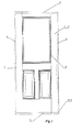
- the present invention discloses an assembly structure of a hubbed door leaf installed with glass, which comprises two door leaf skins 1 and 2 with opening, a top and a bottom lacing materials 3, a left and a right lacing material 4, a handle reinforcement member 5, and a glass ejected-frame 6.
- the said door skin 1 and 2 has a thickness of from about 1 MM to 4 MM; the four edges thereof are designed to be flush surface so as to be closely adhered to the top, the bottom. the left, and the right lacing materials 3 and 4 and then assembled.
- the said lacing material can be polyvinyl chloride foam profile, or wood, or steel, or ejected plastic. etc.
- the four edges of the opening of the door skin 1 are designed to be U shape structure 7 which are formed in one body.
- the four edges of the opening of the other door skin 2 are L shape structure 8 which are formed in one body; the rib 9 thereof inlays with the groove 10 of the U shape structure 7 when assembled in order to position. A space of about 0.5 by 2.3 MM is left between the rib 9 and the groove 10 after being assembled in order to prevent the overflow of the adhesive when assembled.
- a horizontal rib 11 is provided at the external edge of the said U shape structure 7, which is utilized to support the multi-layer glass laid on the opening of the door.
- a groove 12 is provided at the surface of the rib, which can be spread with adhesive such as silicone before assembling the glass in order to closely bond the door and the glass so as to increase the function of watertight and gastight.
- the top of the U shape structure 11 is provided with two saw-shaped slopes 13 which form a horizontal groove with the external edge of L shape structure 8.
- the horizontal groove is provided to be inserted by the glass hold-down or the glass ejected-frame so as to fix the single layer or multi-layer glass.
- the material of the said single layer or multi-layer glass ejected-frame can be wood, or steel, or polyvinyl chloride extrude profile, or PVC foam profile, or PVC plus wood scraps, or polystyrene, or polypropylene, or polypropylene plus fiber glass.
- the material of the door skin 1 and 2 of the present invention can be the Sheet Molding Compound of reinforced fiber glass (referring to R.O.C. Invention patent No. 69423), or wood fiber, or steel, or wood; the surface thereof can be a smooth surface without wood vein or be a mimetic wood vein.
- the depth of wood vein is about 0.05 to 0.2 MM.
- the opposite side of the said skin is a rough surface so as to increase the friction when the door is assembled by the adhesive.
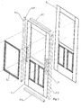
- the procedure of the assembly structure of hubbed door installed with glass is as follows ( please refer to Fig. 2 ): Assembling the door skin 1 and 2, the top and the bottom lacing material 3 , and the left and the right lacing material 4 with adhesive. Then, dispose a reinforcement member 5 at the handle position to enhance the mechanical strength of the handle while locked.
- the openings of the two skins halve and assemble each other ( please refer to Fig. 3.)
- the adhesive can be used before halving in a practical example in order to increase its firmness.
- the left and the right lacing materials are position-bonded, by ribs, to the flush-sided door skin.
- the top and the bottom lacing materials are positioned through the milled notchs 4-3 ( please refer to Fig.
- the present invention directly forms the edges of opening in one body during the manufacturing of the door skin and designs the edges of opening to be a halving structure to match the glass ejected-frame, wherein the advantages are:
Landscapes
- Engineering & Computer Science (AREA)
- Civil Engineering (AREA)
- Structural Engineering (AREA)
- Securing Of Glass Panes Or The Like (AREA)
Abstract
Description
- In the prior art of door manufacturing, it is very common to cut an opening on the door and install glass to make change of the traditional door so as to meet the various needs of the market. However, problems are produced on the door manufacturing to achieve this goal:
- 1. The manufacturing efficiency is affected due to the necessity of increasing the processing of CNC center and the procedure of installing milling groove lacing materials to the four sides of the opening.
- 2. The waste from cutting the opening is wasted.
- 3. The prior halving glass assembling structure is not molded in one body , which causes less watertight and needs to be locked by screw and to be decorated by screw lid. The assembling process is much more complicated.
- 4. The prior halving structure door. which comprises two glass decorating frames, needs to be assembled and painted manually, which affects the efficiency.
- 5. The glass ejected-frame bulges out of the door skin. Consequently, the prior halving structure is unsuitable for a sliding door.
-
- To solve the said problems of production efficiency, cost, waste disposal existing in the door manufacturing of prior art, the present invention discloses a refinement of R.O.C. New Model No. 107146 " Improvement of the Assembly Structure of the Hubbed Door ". More particularly, the present invention discloses a refinement of the assembly structure of hubbed door installed with glass.
-
- Fig. 1 is an assembly drawing of the door structure of the present invention.
- Fig. 2 is an exploded view of the door assembly structure of the present invention.
- Fig. 3 is a door halving structure of the present invention.
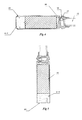
- Fig. 4 is a transverse section drawing of Fig. 1 indicating the door leaf assembly structure of the present invention.
- Fig. 5 is a vertical section drawing of Fig. 1 indicating the door leaf assembly structure of the present invention.
- Fig. 6 is an explanatory drawing of the door leaf structure and the glass ejected-frame.
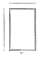
- Fig. 7 is a three-view drawing of the glass ejected-frame.
- Fig. 8 is a section drawing of the glass ejected-frame.
-
-
- 1 and 2 : The skin of the hubbed door.
- 3 : The top lacing material and the bottom lacing material.
- 3-1 : The top lacing material.
- 3-2 : The bottom lacing material.
- 4 : The left lacing material and the right lacing material.
- 4-1 : The left lacing material.
- 4-2 : The right lacing material.
- 4-3 : The notch milled at the top end and the bottom end of the left lacing material and the right lacing material.
- 5 : The handle reinforcement menber.
- 6 : The glass ejected frame.
- 7 : The U shape structure of the door skin.
- 8 : The L shape structure of the door skin.
- 9 : The rib of the L shape structure.
- 10 : The groove of the U shape structure.
- 11 : The horizontal rib of the U shape structure.
- 12 : The groove injected with silicone.
- 13 : The slope of saw shape.
- 14 : The reinforcement rib.
- 15 : The single layer of multi-layer glass.
- 16 : The reinforcement rib of the glass ejected-frame.
- 17 : The footing post of the glass ejected-frame.
- 18 : The inlay structure of the glass ejected-frame.
- 19 : The milled groove at the end of the lacing material.
- 20 : The milled groove at the end of the bottom lacing material.
- 21 : The ammonium polyester foaming plastic.
-
- The accompanying sheets of drawing allow us to appreciate the art contents of the present invention.
- The present invention discloses an assembly structure of a hubbed door leaf installed with glass, which comprises two
door leaf skins materials 3, a left and a right lacingmaterial 4, ahandle reinforcement member 5, and a glass ejected-frame 6.
The saiddoor skin materials door skin 1 are designed to beU shape structure 7 which are formed in one body. The four edges of the opening of theother door skin 2 areL shape structure 8 which are formed in one body; therib 9 thereof inlays with thegroove 10 of theU shape structure 7 when assembled in order to position. A space of about 0.5 by 2.3 MM is left between therib 9 and thegroove 10 after being assembled in order to prevent the overflow of the adhesive when assembled. - A
horizontal rib 11 is provided at the external edge of the saidU shape structure 7, which is utilized to support the multi-layer glass laid on the opening of the door. Agroove 12 is provided at the surface of the rib, which can be spread with adhesive such as silicone before assembling the glass in order to closely bond the door and the glass so as to increase the function of watertight and gastight. The top of theU shape structure 11 is provided with two saw-shapedslopes 13 which form a horizontal groove with the external edge ofL shape structure 8. The horizontal groove is provided to be inserted by the glass hold-down or the glass ejected-frame so as to fix the single layer or multi-layer glass. - The material of the said single layer or multi-layer glass ejected-frame can be wood, or steel, or polyvinyl chloride extrude profile, or PVC foam profile, or PVC plus wood scraps, or polystyrene, or polypropylene, or polypropylene plus fiber glass.
- The material of the
door skin - The procedure of the assembly structure of hubbed door installed with glass is as follows ( please refer to Fig. 2 ):
Assembling thedoor skin bottom lacing material 3 , and the left and theright lacing material 4 with adhesive. Then, dispose areinforcement member 5 at the handle position to enhance the mechanical strength of the handle while locked. The openings of the two skins halve and assemble each other ( please refer to Fig. 3.) The adhesive can be used before halving in a practical example in order to increase its firmness. The left and the right lacing materials are position-bonded, by ribs, to the flush-sided door skin. The top and the bottom lacing materials are positioned through the milled notchs 4-3 ( please refer to Fig. 1 and Fig.2 ) at the top and the bottom ends of the left and the right lacing materials so as to form a closed cabin therebetween. The bottom lacing material is then drilled with a hole through which the ammoniumpolyester foaming plastic 21 is filled into the cabin so as to assemble the door ( please refer to Fig.4 and Fig.5.) Then, the glass is laid in and fixed by the hold-down or the glass ejected-frame 6. - To refine the overlaborate procedure. such as the necessity of processing by CNC center and of assembling the lacing material at the edges of opening, of the traditional hubbed door installed with glass, the present invention directly forms the edges of opening in one body during the manufacturing of the door skin and designs the edges of opening to be a halving structure to match the glass ejected-frame, wherein the advantages are:
- 1. Saving the cost of lacing material.
- 2. Decreasing the assembly labor by the halving assembly structure matching the glass ejected-frame.
- 3. Forming in one body so as to avoid the procedure of cutting the opening, whereby to decrease the production of waste and to obtain good water tight and air tight.
- 4. A reinforcement rib is designed at both the U shape structure and the glass ejected-frame structure to be strong enough to carry heavier load.
- 5. The dimension of glass opening is 22 inches by 36 inches which is most commonly used.
- 6. The maximum width of the door is 35.75 inches which can vary depending on various needs.
- 7. The bottom lacing material used in the swing door and window has two grooves so as to install the soft air tight lacing material much easier.
- 8. The bottom lacing material used in the swing door and window can be drilled the hole to install the roller.
-
Claims (6)
- A refined assembly structure of hubbed door installed with glass comprising two door skins with opening, the top lacing material, the bottom lacing material, the left lacing material, the right lacing material, a handle reinforcement member, and a multi-layer glass ejected-frame. The four edges of the door skin are smooth in order to adhere to the surrounding lacing material when assembled. In addition, a reinforcement member is laid into the handle position so as to increase the mechanical strength of the handle when locked. The openings of the two door skins have halving structure to halve-joint together while assembled to form a closed cabin therebetween. The bottom lacing material is then drilled with a hole through which the ammonium polyester foaming plastic is filled into the cabin so as to finish the assembling of the said door.
- A refined assembly structure of hubbed door installed with glass as defined in Claim 1, wherein the opening of the door skin have a halving structure which is formed in one body to halve-joint together while assembled to form a closed cabin therebetween to lay the single layer or multi-layer glass. The shape of the door opening is not limited to a certain one.
- A refined assembly structure of hubbed door installed with glass as defined in Claim 1 or Claim 2, wherein the opening can be inlaid with a glass ejected-frame to fix the multi-layer glass. The material of the glass ejected-frame can be wood, or steel, or polyvinyl chloride extrude profile, or PVC foam profile, or PVC plus wood scraps, or polystyrene, or polypropylene, or polypropylene plus fiber glass; the surface thereof can be a smooth surface without wood vein or be a mimetic wood vein. The depth of wood vein is 0.05 to 1.0 MM.
- A refined assembly structure of hubbed door installed with glass as defined in Claim 1, wherein the material of the door skin can be the Sheet Molding Compound of reinforced fiber glass, or wood fiber, or steel, or wood; the surface thereof can be a smooth surface without wood vein or be a mimetic wood vein. The depth of wood vein is 0.05 to 0.2 MM. The opposite side of the said skin is a rough surface so as to increase the friction when the door is assembled by the adhesive
- A refined assembly structure of hubbed door installed with glass as defined in Claim 1, wherein the material of the lacing material can be polyvinyl chloride extrude profile, or PVC foam profile, or wood, or steel, or ejected plastic.
- A refined assembly structure of hubbed door installed with glass as defined in Claim 1 can be manufactured into various dimensions and assembled to doors of different widths so as to meet different needs.
Priority Applications (5)
| Application Number | Priority Date | Filing Date | Title |
|---|---|---|---|
| TW090200872U TW452005U (en) | 2001-01-17 | 2001-01-17 | Improved assembling structure for pressure molded door board with set in glass |
| ES01106449T ES2369135T3 (en) | 2001-03-23 | 2001-03-23 | DOOR PANEL ASSEMBLY WITH GLASS FILLING ELEMENT. |
| EP01106449A EP1255020B1 (en) | 2001-01-17 | 2001-03-23 | Door leaf assembly with filling element of glass |
| CA002342547A CA2342547C (en) | 2001-01-17 | 2001-03-30 | A refined assembly structure of hubbed door installed with glass |
| US09/853,593 US6729095B2 (en) | 2001-01-17 | 2001-05-14 | Refined assembly structure of hubbed door leaf installed with glass |
Applications Claiming Priority (3)
| Application Number | Priority Date | Filing Date | Title |
|---|---|---|---|
| TW090200872U TW452005U (en) | 2001-01-17 | 2001-01-17 | Improved assembling structure for pressure molded door board with set in glass |
| EP01106449A EP1255020B1 (en) | 2001-01-17 | 2001-03-23 | Door leaf assembly with filling element of glass |
| CA002342547A CA2342547C (en) | 2001-01-17 | 2001-03-30 | A refined assembly structure of hubbed door installed with glass |
Publications (2)
| Publication Number | Publication Date |
|---|---|
| EP1255020A1 true EP1255020A1 (en) | 2002-11-06 |
| EP1255020B1 EP1255020B1 (en) | 2011-07-06 |
Family
ID=27171497
Family Applications (1)
| Application Number | Title | Priority Date | Filing Date |
|---|---|---|---|
| EP01106449A Expired - Lifetime EP1255020B1 (en) | 2001-01-17 | 2001-03-23 | Door leaf assembly with filling element of glass |
Country Status (4)
| Country | Link |
|---|---|
| US (1) | US6729095B2 (en) |
| EP (1) | EP1255020B1 (en) |
| CA (1) | CA2342547C (en) |
| TW (1) | TW452005U (en) |
Cited By (2)
| Publication number | Priority date | Publication date | Assignee | Title |
|---|---|---|---|---|
| WO2005080737A1 (en) * | 2004-02-25 | 2005-09-01 | Vest-Wood Sverige Ab | Arrangement and method for glazing of door |
| CN1763347B (en) * | 2004-10-20 | 2010-04-28 | 卡普斯通工程株式会社 | Door |
Families Citing this family (28)
| Publication number | Priority date | Publication date | Assignee | Title |
|---|---|---|---|---|
| US7434365B2 (en) * | 2003-09-03 | 2008-10-14 | Gary Robert Geller | Drawer or door front assembly |
| US7506484B2 (en) * | 2004-07-01 | 2009-03-24 | Gary Robert Geller | Drawer or door front assembly with integral port |
| US7520105B2 (en) * | 2005-07-26 | 2009-04-21 | Gary Robert Geller | Drawer or door front assembly with reconfigurable inserts panel |
| TWI402412B (en) * | 2006-03-06 | 2013-07-21 | Masonite Corp | Door with glass insert and method for assembling the same |
| US7997040B2 (en) * | 2007-03-06 | 2011-08-16 | Masonite Corporation | Door with glass insert and method for assembling the same |
| US7448174B2 (en) * | 2006-05-09 | 2008-11-11 | Odl, Incorporated | Integral screwless window assembly |
| USD631172S1 (en) | 2006-11-16 | 2011-01-18 | Therma-Tru Corp. | Window frame for a door |
| GB0704181D0 (en) * | 2007-03-03 | 2007-04-11 | Lssd Uk Ltd | Composite doors |
| US20080251183A1 (en) * | 2007-04-13 | 2008-10-16 | Turner Daniel S | Apparatus and method of fabricating a door |
| US7748120B2 (en) * | 2007-04-13 | 2010-07-06 | Turner Daniel S | Apparatus and method of fabricating a door |
| US20110131921A1 (en) * | 2009-12-08 | 2011-06-09 | Kuei Yung Wang Chen | Synthetic door with improved fire resistance |
| US20120117881A1 (en) * | 2010-11-17 | 2012-05-17 | Stanley Black & Decker, Inc. | Door glazing assembly |
| USD687164S1 (en) | 2012-02-13 | 2013-07-30 | Masonite Corporation | Door |
| HK1198410A2 (en) * | 2014-01-20 | 2015-10-16 | 黄龙辉 | Forced entry resistance system for wooden doors |
| US9016030B1 (en) * | 2014-06-10 | 2015-04-28 | Ryan D. Steele | Metal door |
| US9175508B1 (en) * | 2014-06-10 | 2015-11-03 | Ryan D. Steele | Metal door |
| CA2949268C (en) * | 2014-07-11 | 2023-10-03 | Masonite Corporation | Door with frameless glazed unit, and related kit and methods |
| US11480009B2 (en) | 2014-07-11 | 2022-10-25 | Masonite Corporation | Door with frameless glazed unit, and related kit and methods |
| US9593526B2 (en) * | 2014-07-31 | 2017-03-14 | Nan Ya Plastics Corporation | Door structure with glass |
| US9500023B2 (en) * | 2015-03-02 | 2016-11-22 | John M. PONIROS | Pre-fabricated structural framing kit and method |
| GB2539282A (en) * | 2015-06-05 | 2016-12-14 | Nanya Plastics Corp | Closure assembly with a window and a method of making the same |
| CA2913424A1 (en) * | 2015-11-23 | 2017-05-23 | Les Portes Alain Bourassa Inc. | Anti-warping system for a solid wood door |
| CA2913423A1 (en) * | 2015-11-23 | 2017-05-23 | Les Portes Alain Bourassa Inc. | Highly energy efficient door |
| CA2969798C (en) * | 2016-06-08 | 2026-04-07 | Masonite Corporation | Door kits and related methods |
| US10968683B2 (en) * | 2017-08-18 | 2021-04-06 | Plastpro 2000, Inc. | Doors comprising glazed unit, and method of making the same |
| US10214953B2 (en) * | 2017-11-29 | 2019-02-26 | Nan Ya Plastics Corporation | Closure member with decorative panel |
| US11203894B1 (en) * | 2021-04-12 | 2021-12-21 | Nan Ya Plastics Corporation | Door panel |
| US12378812B1 (en) * | 2022-02-18 | 2025-08-05 | Andersen Corporation | Glass lite retention systems and methods for improved performance |
Citations (7)
| Publication number | Priority date | Publication date | Assignee | Title |
|---|---|---|---|---|
| US5239799A (en) | 1991-08-28 | 1993-08-31 | The Stanley Works | Insulated door with synthetic resin skins |
| EP0773342A1 (en) | 1995-06-14 | 1997-05-14 | Nan Ya Plastics Corporation | Compression molded door assembly |
| US5887398A (en) | 1997-03-17 | 1999-03-30 | Chen; Kuei Yung Wang | Synthetic door casement structure for patio doors and like, and method |
| EP0907000A1 (en) | 1997-10-01 | 1999-04-07 | Nan Ya Plastics Corp., Taipei Taiwan | A door slab assemble structure for the partly hollow door skin and glass |
| US5894706A (en) | 1996-08-13 | 1999-04-20 | Herbst; Walter B. | Molded window door and method |
| EP1036908A2 (en) | 1999-03-18 | 2000-09-20 | B. Kreye Kunststoff-, Metall- u. Biegetechnik GmbH | Door leaf |
| EP1094192A1 (en) | 1999-10-22 | 2001-04-25 | Nan Ya Plastics Corporation | Patio door with integral glazing frame |
Family Cites Families (7)
| Publication number | Priority date | Publication date | Assignee | Title |
|---|---|---|---|---|
| US4327535A (en) * | 1980-02-21 | 1982-05-04 | Peachtree Doors, Inc. | Door with glass panel |
| US4550540A (en) | 1983-01-07 | 1985-11-05 | Therma-Tru Corp. | Compression molded door assembly |
| US6161363A (en) * | 1995-06-07 | 2000-12-19 | Herbst; Walter B. | Molded door frame and method |
| US6024908A (en) * | 1997-10-03 | 2000-02-15 | Koncelik; Kenneth J. | Method of molding a thermostat polymer door skin, shelf stable thermostat molding composition, and door assembly using the door skins so formed |
| US6311454B1 (en) * | 1999-02-18 | 2001-11-06 | Globe Door, L.L.C. | Door construction |
| US6415558B1 (en) * | 2000-07-06 | 2002-07-09 | Autoquip Corporation | Tornado shelter |
| US6393779B1 (en) * | 2000-07-19 | 2002-05-28 | Ex Cell Cellular Pvc Building Components, Inc. | Door frame assembly and method of mounting the same |
-
2001
- 2001-01-17 TW TW090200872U patent/TW452005U/en not_active IP Right Cessation
- 2001-03-23 EP EP01106449A patent/EP1255020B1/en not_active Expired - Lifetime
- 2001-03-30 CA CA002342547A patent/CA2342547C/en not_active Expired - Lifetime
- 2001-05-14 US US09/853,593 patent/US6729095B2/en not_active Expired - Lifetime
Patent Citations (7)
| Publication number | Priority date | Publication date | Assignee | Title |
|---|---|---|---|---|
| US5239799A (en) | 1991-08-28 | 1993-08-31 | The Stanley Works | Insulated door with synthetic resin skins |
| EP0773342A1 (en) | 1995-06-14 | 1997-05-14 | Nan Ya Plastics Corporation | Compression molded door assembly |
| US5894706A (en) | 1996-08-13 | 1999-04-20 | Herbst; Walter B. | Molded window door and method |
| US5887398A (en) | 1997-03-17 | 1999-03-30 | Chen; Kuei Yung Wang | Synthetic door casement structure for patio doors and like, and method |
| EP0907000A1 (en) | 1997-10-01 | 1999-04-07 | Nan Ya Plastics Corp., Taipei Taiwan | A door slab assemble structure for the partly hollow door skin and glass |
| EP1036908A2 (en) | 1999-03-18 | 2000-09-20 | B. Kreye Kunststoff-, Metall- u. Biegetechnik GmbH | Door leaf |
| EP1094192A1 (en) | 1999-10-22 | 2001-04-25 | Nan Ya Plastics Corporation | Patio door with integral glazing frame |
Cited By (2)
| Publication number | Priority date | Publication date | Assignee | Title |
|---|---|---|---|---|
| WO2005080737A1 (en) * | 2004-02-25 | 2005-09-01 | Vest-Wood Sverige Ab | Arrangement and method for glazing of door |
| CN1763347B (en) * | 2004-10-20 | 2010-04-28 | 卡普斯通工程株式会社 | Door |
Also Published As
| Publication number | Publication date |
|---|---|
| TW452005U (en) | 2001-08-21 |
| CA2342547C (en) | 2009-06-30 |
| EP1255020B1 (en) | 2011-07-06 |
| US20020092254A1 (en) | 2002-07-18 |
| CA2342547A1 (en) | 2002-09-30 |
| US6729095B2 (en) | 2004-05-04 |
Similar Documents
| Publication | Publication Date | Title |
|---|---|---|
| CA2342547C (en) | A refined assembly structure of hubbed door installed with glass | |
| CA2817433C (en) | Door jamb member, door jamb assembly incorporating same and kit therefor | |
| US6453638B2 (en) | Press molded door with improved reinforcement material and stile structure | |
| US6050037A (en) | Brick molding having an integral hinge and a concealed mounting surface | |
| US6866081B1 (en) | Exterior door or window having extruded composite frame | |
| CA2327966A1 (en) | Solid core vinyl screen door | |
| US20110000145A1 (en) | Decorative molding | |
| US5887398A (en) | Synthetic door casement structure for patio doors and like, and method | |
| CA2100288A1 (en) | Shutter assembly | |
| US2983001A (en) | Window structure | |
| GB2276902A (en) | Door core with moulded-on edge | |
| US5208924A (en) | Decorative bathtub front enclosure | |
| CN2464895Y (en) | Improved glass installed moulding door assembling structure | |
| CA2211279A1 (en) | A door slab assemble structure for the partly hollow door skin and glass | |
| KR200493451Y1 (en) | Door and window frame | |
| KR200355667Y1 (en) | Structure for assembling frame of door product | |
| CN217175494U (en) | Anti-deformation floor | |
| JPS6020793Y2 (en) | carved wood door | |
| KR101386311B1 (en) | Prefabricated system door and process for preparing the same | |
| KR200355664Y1 (en) | assembly structure of a sliding door frame and window frame | |
| KR200316924Y1 (en) | Jointing structure of chassis product | |
| CN211081558U (en) | Extremely simple narrow frame door | |
| JPH0328690Y2 (en) | ||
| JPS6143911Y2 (en) | ||
| KR200341306Y1 (en) | the structure of under doorframe |
Legal Events
| Date | Code | Title | Description |
|---|---|---|---|
| PUAI | Public reference made under article 153(3) epc to a published international application that has entered the european phase |
Free format text: ORIGINAL CODE: 0009012 |
|
| AK | Designated contracting states |
Kind code of ref document: A1 Designated state(s): AT BE CH CY DE DK ES FI FR GB GR IE IT LI LU MC NL PT SE TR |
|
| AX | Request for extension of the european patent |
Free format text: AL;LT;LV;MK;RO;SI |
|
| 17P | Request for examination filed |
Effective date: 20030506 |
|
| AKX | Designation fees paid |
Designated state(s): DE ES FR GB IT NL |
|
| 17Q | First examination report despatched |
Effective date: 20081117 |
|
| GRAP | Despatch of communication of intention to grant a patent |
Free format text: ORIGINAL CODE: EPIDOSNIGR1 |
|
| GRAS | Grant fee paid |
Free format text: ORIGINAL CODE: EPIDOSNIGR3 |
|
| GRAA | (expected) grant |
Free format text: ORIGINAL CODE: 0009210 |
|
| AK | Designated contracting states |
Kind code of ref document: B1 Designated state(s): DE ES FR GB IT NL |
|
| REG | Reference to a national code |
Ref country code: GB Ref legal event code: FG4D |
|
| REG | Reference to a national code |
Ref country code: DE Ref legal event code: R096 Ref document number: 60144896 Country of ref document: DE Effective date: 20110825 |
|
| REG | Reference to a national code |
Ref country code: NL Ref legal event code: T3 |
|
| REG | Reference to a national code |
Ref country code: ES Ref legal event code: FG2A Ref document number: 2369135 Country of ref document: ES Kind code of ref document: T3 Effective date: 20111125 |
|
| PLBE | No opposition filed within time limit |
Free format text: ORIGINAL CODE: 0009261 |
|
| STAA | Information on the status of an ep patent application or granted ep patent |
Free format text: STATUS: NO OPPOSITION FILED WITHIN TIME LIMIT |
|
| 26N | No opposition filed |
Effective date: 20120411 |
|
| REG | Reference to a national code |
Ref country code: DE Ref legal event code: R097 Ref document number: 60144896 Country of ref document: DE Effective date: 20120411 |
|
| REG | Reference to a national code |
Ref country code: FR Ref legal event code: PLFP Year of fee payment: 16 |
|
| REG | Reference to a national code |
Ref country code: FR Ref legal event code: PLFP Year of fee payment: 17 |
|
| PGFP | Annual fee paid to national office [announced via postgrant information from national office to epo] |
Ref country code: NL Payment date: 20170323 Year of fee payment: 17 |
|
| PGFP | Annual fee paid to national office [announced via postgrant information from national office to epo] |
Ref country code: DE Payment date: 20170330 Year of fee payment: 17 |
|
| PGFP | Annual fee paid to national office [announced via postgrant information from national office to epo] |
Ref country code: ES Payment date: 20170323 Year of fee payment: 17 Ref country code: IT Payment date: 20170323 Year of fee payment: 17 |
|
| REG | Reference to a national code |
Ref country code: FR Ref legal event code: PLFP Year of fee payment: 18 |
|
| REG | Reference to a national code |
Ref country code: DE Ref legal event code: R119 Ref document number: 60144896 Country of ref document: DE |
|
| REG | Reference to a national code |
Ref country code: NL Ref legal event code: MM Effective date: 20180401 |
|
| PG25 | Lapsed in a contracting state [announced via postgrant information from national office to epo] |
Ref country code: NL Free format text: LAPSE BECAUSE OF NON-PAYMENT OF DUE FEES Effective date: 20180401 |
|
| PG25 | Lapsed in a contracting state [announced via postgrant information from national office to epo] |
Ref country code: DE Free format text: LAPSE BECAUSE OF NON-PAYMENT OF DUE FEES Effective date: 20181002 |
|
| PG25 | Lapsed in a contracting state [announced via postgrant information from national office to epo] |
Ref country code: IT Free format text: LAPSE BECAUSE OF NON-PAYMENT OF DUE FEES Effective date: 20180323 |
|
| REG | Reference to a national code |
Ref country code: ES Ref legal event code: FD2A Effective date: 20190911 |
|
| PG25 | Lapsed in a contracting state [announced via postgrant information from national office to epo] |
Ref country code: ES Free format text: LAPSE BECAUSE OF NON-PAYMENT OF DUE FEES Effective date: 20180324 |
|
| PGFP | Annual fee paid to national office [announced via postgrant information from national office to epo] |
Ref country code: GB Payment date: 20200319 Year of fee payment: 20 |
|
| PGFP | Annual fee paid to national office [announced via postgrant information from national office to epo] |
Ref country code: FR Payment date: 20200408 Year of fee payment: 20 |
|
| REG | Reference to a national code |
Ref country code: GB Ref legal event code: PE20 Expiry date: 20210322 |
|
| PG25 | Lapsed in a contracting state [announced via postgrant information from national office to epo] |
Ref country code: GB Free format text: LAPSE BECAUSE OF EXPIRATION OF PROTECTION Effective date: 20210322 |