This application is a continuation-in-part of U.S. Patent
Application Serial No. 09/139,081 filed on August 24, 1998, which
in turn is a continuation-in-part of U.S. Patent Application Serial
No. 08/715,724, filed September 19, 1996, the entire content
of each prior application being incorporated expressly hereinto
by reference.
This invention relates to stain-resistant, dyeable sheath/core
filaments and methods. More particularly, this invention relates
to sheath/core filaments wherein the core component is susceptible
to dyeing by dye chemicals in a dye bath, while the sheath
component is resistant to dyeing by such dye chemicals in the dye
bath.
As used herein, "dyed" refers to the results of an intentional
coloration process performed by exhaust or continuous dyeing
methods that are known in the art after the material (i.e., fiber)
is extruded by incorporating one or more colored chemical
compositions into the material at elevated temperature. In contrast,
the term "stained" means the discoloration of fibers caused
by the binding of a colored material either ionically, covalently,
or through chemical partitioning to the fiber. The term
"stain resistant" and "stain resistance" as used herein with respect
to polyamide fibers or carpets refers to the ability of the
fiber or carpet to resist red drink and/or coffee stains. "Inherently
chemically compatible" means that the materials referred to
are miscible.
Polyamide fibers are relatively inexpensive and offer a combination
of desirable qualities such as comfort, warmth and ease of
manufacture into a broad range of colors, patterns and textures.
As a result, polyamide fibers are widely used in a variety of
household and commercial articles, including, e.g., carpets, drapery
material, upholstery and clothing. Carpets made from polyamide
fibers are a popular floor covering for both residential
and commercial applications.
Polyamide fibers tend to be easily permanently stained by certain
natural and artificial colorants such as those found in such common
household beverages as coffee, wine and soft drinks. Such
household beverages may contain a variety of colored anionic
compounds including acid dyes, such as the red dyes used in children's
drinks. The stains resulting from such compounds cannot
easily be removed under ordinary cleaning conditions.
The ability of a staining material like an acid dye to bind to a
fiber is a function of the type of active functional groups on
the fiber and of the staining material. For example, polyamides
usually have terminal (often protonated) amine groups which bond
with negatively charged active groups on an acid dye (or staining
agent).
A commonly used acid dye colorant and one which severely stains
nylon at room temperature is Color Index ("C.I.") Food Red 17,
also known as FD&C Red Dye 40. Acid dyes such as C.I. Food Red 17
often form strong ionic bonds with the protonated terminal amine
groups in the polyamide polymers, thereby dyeing, i.e., staining,
the fiber. Thus, in contrast to soils which are capable of being
physically removed from the polyamide carpet by typical cleaning
procedures, acid dye colorants such as C.I. Food Red 17 penetrate
and chemically react with the polyamide to form bonds therewith
which make complete removal of such colorants from the polyamide
fibers impractical or impossible.
The exact mechanism of coffee as a staining agent is not well understood.
However, as with acid dye stains, coffee stains are notoriously
difficult to remove from polyamide carpet by conventional
cleaning procedures.
This severe staining of carpeting is a major problem for consumers.
In fact, surveys show that more carpets are replaced due to
staining than due to wear. Accordingly, it is desirable to provide
polyamide fibers which resist common household stains like
red drink and coffee stains, thereby increasing the life of the
carpet.
Methods to decrease the acid dye affinity of nylons by reducing
the number of dye sites are known. For example, U.S. Patent No.
3,328,341 to Corbin, et al. describes decreasing nylon dyeability
with butrylactone. U.S. Patent No. 3,846,507 to Thomm et al. describes
reducing acid dye affinity of polyamide by blending a
polyamide with a polymer having benzene sulfonate functionality.
U.S. Patent No. 5,108,684 to Anton et al. describes fibers made
from polyamide copolymers containing 0.25 to 4.0 percent by
weight of an aromatic sulfonate, which are stain-resistant to
acid dyes. U.S. Patent No. 5,340,886, Hoyt et al. describes acid
dye resistant polyamide fibers made by incorporating within the
polymer sufficient SO3H groups or salts thereof to give the polymer
a sulfur content of between about 1 and about 160 equivalents
per 106 grams polymer and, chemically blocking with a chemical
blocking agent a portion of amine end groups present in the
sulfonated polymer. Modified polymers such as described in these
patents are generally expensive to make.
In addition to polymer modifications, topical treatments for carpets
have been proposed as a cost effective means to impart acid
dye resistance to polyamide carpet fibers. These topical treatments
may be sulfonated materials that act as "colorless dyes"
and bind the amine dye sites on the polyamide polymer. Sulfonated
products for topical application to polyamide substrates are described
in, for example, U.S. Patent No. 4,963,409 to Liss et al.;
U.S. Patent No. 5,223,340 to Moss, III, et al.; U.S. Patent No.
5,316,850 to Sargent et al.; and U.S. Patent No. 5,436,049 to Hu.
(Hu describes also a polyamide substrate that is made by melt mixing
a polyamide with an amine end group reducing compound prior
to fiber formation.) Topical treatments tend to be non-permanent
and to wash away with one or more shampooings of the carpet.
Fibers may be formed in a variety of shapes and from a variety of
materials. For example, some fibers have more than one type of
polymer in distinct longitudinally co-extensive portions of the
transverse cross-section and extending along the length of the
fiber. Fibers that have two such portions are known as "bicomponent
fibers". Bicomponent fibers having one of the portions
surrounding or substantially surrounding the other are referred
to as having a sheath/core configuration.
Sheath/core bicomponent polyamide fibers are known. U.S. Patent
No. 5,445,884 to Hoyt and Wilson discloses a filament with reduced
stainability having a polyamide core and a sheath of a hydrophobic
polymer. The weight ratio between the core and sheath is
from about 2:1 to about 10:1. If the sheath is very thin, a
compatibilizer must be used. Compatibilizers are generally expensive.
The compatibilizer can, in some cases, be eliminated by making
the sheath relatively thick, i.e., more than 15 wt % of the
cross-section. However, if the sheath material is expensive, this
also can add significantly to the cost of the fibers.
U.S. Patent No. 4,075,378 to Anton discloses sheath/core bicomponent
polyamide fibers containing a polyamide core and a
polyamide sheath. The core polyamide is acid-dyeable while the
sheath polyamide is basic-dyeable due to sulfonation.
U.S. Patent No. 3,679,541 to Davis et al. describes a sheath/core
bicomponent filament having soil-release, anti-soil redeposition
and antistatic properties through use of a copolyester or
copolyamide sheath around a polyamide core.
U.S. Patent No. 3,645,819 to Fujii et al. discloses polyamide bicomponent
fibers for use in tire cords, bowstrings, fishing nets
and racket guts.
U.S. Patent No. 3,616,183 to Brayford discloses polyester sheathcore
bicomponent fibers having antistatic and soil-release
characteristics.
U.S. Patent No. 2,989,798 to Bannerman describes sheath/core bicomponent
which is said to have improved dyeability by modifying
the amine end group level of the sheath relative to the core. The
sheath has less amine end groups than the core.
Fibers that are non-round in transverse cross-section are known.
For example, U.S. Patent Nos. 2,939,202 and 2,939,201, both to
Holland, describe fibers having a trilobal cross-section.
Polyamide fibers may be dyed to popular colors, usually after
being tufted or woven into carpet face fiber. The dyestuffs used
to dye the fibers are subject to fading. One mode of fading of
dyed yarns is via ozone. This is a particular problem in areas
that are near coastlines (i.e., hot and humid) or in homes that
have electrostatic dust precipitators. Carpets installed in automobiles
are also subject to heat and humidity. Ozone reacts with
dyestuffs, especially disperse and cationic dyestuffs, and renders
them colorless or off-shade. Acid dyestuffs are also susceptible
to ozone fading. Fading is a significant barrier to the sales
of uncolored nylon 6 yarn (which is intended to be dyed) into
the commercial carpet (contrasted to the residential) market. To
achieve acceptable ozone fading resistance in commercial applications.
the yarn often must be pigmented during spinning rather
than using the more flexible (with respect to color and style)
dyeing processes that are performed at the carpet mill rather
than upstream at the fiber producer.
Broadly, the present invention relates to dyeable filaments and
methods. More specifically, the present invention relates to
bath-dyed or dyeable filaments and methods for sheath/core filaments
having a core and a sheath which surrounds entirely the core.
The core is formed of a core polymer which is susceptible to
dyeing by a bath dye chemical, while the sheath is formed of a
sheath polymer which is resistant to dyeing by the bath dye
chemical. When the filament is brought into contact with a dye
bath containing the dye chemical, the dye chemical in the dye
bath will be physically transported (that is, will diffuse, migrate
or penetrate) through said sheath polymer to cause the core
polymer to be dyed a color of the dye chemical, while the sheath
polymer is substantially undyed thereby.
These and other aspects and advantages will become more apparent
after careful consideration is given to the following detailed
description of the preferred exemplary embodiments thereof.
The patent or application file contains at least one drawing executed
in color. Copies of this patent or patent application
publication with color drawing(s) will be provided by the Office
upon request and payment of the necessary fee.
Reference will hereinafter be made to the accompanying drawings,
wherein like reference numerals throughout the various FIGURES
denote like structural elements, and wherein;
To promote an understanding of the principles of the present invention,
descriptions of specific embodiments of the invention
follow and specific language is used to describe them. It will
nevertheless be understood that no limitation of the scope of the
invention is intended by the use of specific language. Alterations,
further modifications and such further applications of the
principles of the invention discussed are contemplated as would
normally occur to one ordinarily skilled in the art to which the
invention pertains.
Dyed carpets made according to the present invention resist ozone
fading. They also resist staining caused by both acid dyes and
coffee and yet are dyeable with conventional polyamide dyeing
methods. They exhibit lightfastness performance comparable to
conventional dyed nylon 6 carpets so that this trait is not sacrificed
(and might be improved).
These carpets are made from bicomponent face fibers composed of a
polyamide core portion substantially or completely surrounded by
a polymer that resists dye migration. The fibers are dyed with
acid dyes, disperse dyes, or other dyes that are known to be susceptible
to ozone fading or shade changes.
The fiber of this invention preferably contains from about 97% by
weight to about 70% by weight of the core portion and from about
3% by weight to about 30% by weight of the sheath portion. More
preferably, the fiber used in the carpet of this invention contains
from about 97% by weight to about 85% by weight of the core
portion and from about 3% by weight to about 15% by weight of the
sheath portion. Most preferably, the fiber contains from about
97% by weight to 90% by weight of the core portion and about 3%
by weight to less than 10% by weight of the sheath portion. In
fact, it is surprising that sheath proportions less than 10
weight % show superior performance over sheath proportions around
10%, especially in ozone fastness.
The core may be formed from any fiber-forming polyamide or copolyamide.
Fiber-forming polyamides suitable for the core include
polymers having, as an integral part of the polymer backbone
chain, recurring amide groups (-CO-NR-) where R is an alkyl,
aryl, alkenyl, or alkynyl substituent. Non-limiting examples of
such polyamides include homopolyamides and copolyamides which are
obtained by the polymerization of lactam or aminocaproic acid or
a copolymerization product from any of the possible permutative
mixtures of diamines, dicarboxylic acids or lactams. The core may
be an acid-dyeable polyamide such as a polyamide having amine end
groups available as dye sites. Possibly, the core may be a basic-dyeable
polyamide, such as made when polyamide forming monomers
are polymerized in the presence of anionic groups such as
sulfonated monomers. Such polyamides and methods of forming them
are well known to those ordinarily skilled in the art and are generally
among the class of polyamides having 15 or less carbon
atoms in a repeating unit (or monomer in the case of mixed
monomer starting materials). More preferably, the polyamide will
have less than seven carbon atoms in the repeating unit such as
in nylon 6. Other polyamides such as nylon 6/6, nylon 12, nylon
11, nylon 6/12, nylon 6/10, etc., that for some reason have been
modified so that they have become stainable with acid dyes or
coffee, may be used. Most preferably, the core polyamide is nylon
6 or nylon 6/6. Possibly, the core polyamide may have an amine
end-group content of from greater than about 5 milliequivalents
per kilogram (meq/kg) to less than about 100 milliequivalents per
kilogram, more preferably from about 20 to about 50 milliequivalents
per kilogram.
The sheath portion of the fiber is composed of a fiber forming
polymer that resists dye migration (at room temperature, relative
to nylon 6). Suitable polymers include polyolefins (e.g., polypropylene,
polybutylene, etc.), fiber-forming polystyrene, fiber-forming
polyurethane, and certain polyamides. Preferably, the
sheath is composed of a polymer that is inherently chemically
compatible with the core polymer. Preferably, the sheath is a
polyamide polymer that is acid dye and coffee stain resistant,
such that when the face fiber is exposed to C.I. Food Red No. 17,
the red drink staining depth of the face fiber is about 15 or
less CIEL*a*b* ΔE units under the Daylight 6500 Standard Illuminant;
and such that when the face fiber is exposed to coffee, the
coffee staining depth under Daylight 6500 Standard Illuminant is
about 10 or less CIEL*a*b* ΔE* units. More preferably, the red
drink staining depth is about 10 or less ΔE*units.
Preferably, the sheath polymer is a polyamide selected from the group consisting of polyamides having the structure:
(a) [NH- (CH2)×-NH-CO-(CH2)y-CO]n
where x and y may be the same or different integers, preferably
from about 4 to about 30 and the sum of x and y is greater than
13, more preferably from about 9 to about 20, and most preferably
from about 9 to about 15 and n is greater than about 40; and
where z is an integer preferably from about 9 to about 30, more
preferably from about 9 to about 20, and most preferably from about
9 to about 15 and m is greater than about 40;
(c) derivatives of (a) or (b) including polymers substituted with
one or more sulfonate, halogenate, aliphatic or aromatic
functionality; and
(d) copolymers and blends of (a), (b) and (c).
The preferable sheath polymers have greater than 80% of the noncarbonyl
backbone or substituent carbons as alkyl, alkenyl, alkynyl,
aryl, fluoroalkyl, fluoroalkenyl, fluoroalkynyl, fluoroaryl,
chloroalkyl, chloroalkenyl, chloroalkynyl, chloroaryl, and the
like, and do not have polar substituents such as hydroxy, amino,
sulfoxyl, carboxyl, nitroxyl, or other such functionalities capable
of hydrogen-bonding. Non-limiting examples of suitable fiber-forming
polyamides which can be used as the sheath polyamide include
nylon 6/10, nylon 6/12, nylon 10, nylon 11 and nylon 12. The
fiber-forming sheath polyamide may be sulfonated but is preferably
substantially sulfonate-free. Optionally, the sheath polyamide
component may have a titratable amine-end-group concentration
of less than about 30 meq/kg, and preferably less than about
15 meq/kg, and desirably less than about 10 meq/kg. If the
polymers are amine end group blocked, useful amine-end-groupblocking
agents include lactones, such as caprolactones and butyrolactones.
Most preferably, the sheath polymer is nylon-6/12 having
an AEG content of less than about 5.0 meq/kg. In preferred
embodiments, the nylon-6/12 sheath polymer is a homopolymer.
As mentioned previously, the sheath of the fiber will preferably
substantially or completely cover the core of the fiber. Methods
for forming sheath/core fibers are known to those of ordinary
skill in the art. One preferred method of forming sheath/core
fibers is described in U.S. Patent No. 5,162,074 to Hills, which
is hereby incorporated by reference for the bicomponent spinning
techniques taught therein. The sheath/core arrangement may be eccentric
or concentric.
The fibers used as face fiber in the carpet of this invention are
preferably multilobal. Trilobal cross-sections are currently preferred.
Additionally, the fibers might contain one or more internal
void spaces, for example, a central axial void.
The fibers used in this invention may be continuous fibers or
staple fibers, either alone or in admixture with other fibers.
The fibers are particularly useful as bulked continuous filament
yarns.
Common melt-spinning and after processing techniques may be employed
to make the fibers. The fibers may be textured to produce
bulked yarns by known methods including stuffer-box crimping,
gear-crimping, edge-crimping, false-twist texturing and hot-fluid
jet bulking. Several ends may be combined in a variety of manners
and twist levels according to conventional techniques, for
example, groups of the fibers may be plied into yarn. The yarn
may be cabled (i.e., plied and twisted). Preferably, the yarn is
heatset.
It is especially preferred and especially beneficial if the
fibers used in the present invention are cabled and heatset. As
those of ordinary skill in the art will recognize, "cabled" refers
to yarn that is plied and twisted. Cabling and heatsetting
can be accomplished according to any method conventionally used
in the art. It is not believed that the method of cabling or
heatsetting is essential to the benefit of the invention. Typically,
conventional dyed and heatset yarn has worse ozone fading
performance (i.e., more fading upon ozone exposure) than dyed
yarn that has not been heatset. However, it was surprisingly discovered
that the carpets of the present invention have little
degradation of ozone fading resistance from heatsetting. That is,
the heatset face yarn on the carpet of the present invention performs
at least as well as, and in some cases better than, nonheatset
yarn.
Also, polyamide yarns will often shrink during heatsetting. Preferably,
the fiber used in this invention has a steam heatsetting
shrinkage value of about 70% or less relative to the steam heatsetting
shrinkage value of fiber which is manufactured in the
identical manner but which consists only of the core polyamide
component.
Carpet may be made from the yarn by conventional carpet making
techniques like weaving or tufting the face fibers into a backing
material and binding the face fiber to the backing with latex or
other adhesives. The carpet may be cut-pile, berber, multilevel
loop, level loop, cut-pile/loop combination or any other style
according to the popular fashion. If it is desired, the carpet of
the present invention may be in the form of carpet tiles or mats.
As an example, in the case of cut-pile carpeting, the yarn is
tufted into a primary backing and the loops are cut to form cut-pile
carpeting. The primary backing may be woven or non-woven and
comprised of nylon, polyester, polypropylene, etc. The cut-pile
carpeting is dyed to the desired shade. A secondary backing, if
required, is adhered to the non-pile side, typically using a latex-based
adhesive. The secondary backing may be jute, polypropylene,
nylon, polyester, etc. The carpet of the present invention
may be foam backed or not. The carpet of the present invention
can be a variety of pile weights, pile heights and styles.
There is not currently believed to be any limitation on the
carpet style.
As noted, the fibers used in the carpets of the present invention
are dyed with dyes, and exhibit surprising resistance to color
fading under exposure to ozone. The fibers may be dyed before the
carpet is made, such as with skein dyeing, or the fibers may be
dyed when already present in the backing. That is, the constructed
carpet may be dyed. Although a variety of dyes are envisioned
for use in the present invention, the presently preferred dyes
are: C.I. Acid Yellow 246, C.I. Acid Red 361, C.I. Acid Blue 277
and combinations of these with each other or other dyes. Dyes of
similar chemical structures are also contemplated as useful to
achieve the beneficial results of the present invention. Disperse
dyes, which are notoriously unstable to ozone exposure are remarkably
benefited by the present invention.
The invention will now be described by referring to the following
detailed examples. These examples are set forth by way of illustration
and are not intended to be limiting in scope. Knit fabrics
are used in some of the following examples to demonstrate
the stain resisting nature of fibers useful to make carpets of
the present invention. This is merely for illustration and it is
believed that the fibers would exhibit substantially identical
attributes as face fiber in carpet.
The following test methods and procedures are used in the Examples:
Linear density, tenacity, elongation, and work to break:
The linear density, tenacity, elongation, and work to break are
measured using test method ASTM D2256-97. The gauge length used
is 10 inches (0.254 meters) and a cross head speed of 10 inchesmin
(0.0042 meters/second) is used.
Boiling water shrinkage:
Boiling water shrinkage is determined using ASTM D2259-71.
Modification ratio:
For non-round cross-sections (e.g., trilobal), modification ratio
is the ratio of the smallest possible circumscribed circle to the
largest possible inscribed circle for a cross section of a filament
from the yarn. The number reported is the average for 10 filaments.
Heatsetting:
The yarn to be heatset is wound into skeins and is heatset in a
standard autoclave used in the carpet industry. The first step of
the heatsetting process in the autoclave involves raising the
temperature to 110° C for 3 minutes at a pressure of 6 psig (41
kPa). The pressure is then released and then the first step is
repeated. The second step of the heatsetting process in the autoclave
involves raising the temperature to 132° C at pressure of 28
psig (193 kPa) for 3 minutes. The pressure is then broken and
this step is repeated two more times.
Ozone exposure procedure:
Using AATCC method 129-1996 (similar to ISO 105-G03) all dyed
samples are subjected to 1, 2, 3, 4, 5 and 6 cycles of ozone fading.
In this method (and other methods herein referencing the
color or color change), the total color differences between exposed
and corresponding unexposed samples are calculated using the
CIEL*a*b* system as described by the Commission Internationale de
l'Eclairage in CIE Publication No. 15 (E-1.3.1) for a Daylight
6500 standard illuminant.
A spectrophotometric measurement of the exposed and unexposed
materials is made and the CIEL*a*b* total color difference
(CIEL*a*b* ΔE* (as used in this application: "ΔE*" or "Delta
E*")) between the exposed and unexposed materials is calculated
under the CIEL*a*b* system. For details of these calculations
see, for example, Billmeyer, Jr., Fred W. and Saltzman, Max,
Principles of Color Technology, John Wiley & Sons, New York
(1966). The lower the ΔE* value (i.e., the total color change
from the unexposed control) the less the color of the material
has changed.
The AATCC Color Change Gray Scale is a scale for visually rating
the color change of a specimen relative to the differences shown
by the scale. A 5 rating represents no color change. A 1 rating
represents severe color change. A 3 rating represents noticeable
but in most cases, acceptable color change. For the purposes of
this application, a delta E* value of 3.4 or less is equivalent
to a 3 rating or better on the AATCC scale. In general, commercially
acceptable ozone resistance performance is a ΔE* rating of
3.2 or less.
As shown in the following examples, the present invention fades
(as measured by ΔE*) after exposure to three cycles of ozone only
one-half or less than a carpet having fiber composed substantially
completely of the core polyamide (i.e., without the
sheath) that is dyed with the same dyes. It should be noted that
in making this comparison, the fibers and yarns used in the invention
and the fibers and yarns made only of the core material
must be of similar denier, cross-sectional shape and texturing.
This is because any one of these factors can affect the apparent
dye shade depth (as measured by the CIEL*a*b* system) of the unexposed
sample used as the control for measuring ozone fade. For
example, as a general rule, lower denier (per filament) yarn appears
to dye less deeply than higher total denier (per filament
yarn). Textured yarn dyes more deeply than untextured yarn, and
so forth. This principle will be understood by those who are of
at least ordinary skill in this art.
Laboratory Simulated continuous dyeing procedure:
A two yard (1.8 meter) sample of knitted tube is used. The volume
of dye formulation is determined by the weight of the fabric to
be dyed. In the examples, a 2.5:1 ratio of ml/g (bath volume to
fabric weight) is used. The knitted tube is dipped into a beaker
containing one of the dye formulations described below. In the
process, the dye saturated fabric is squeezed and released several
times distributing the dye bath uniformly throughout the
knitted tube. The knitted tube is then exposed to 99°C steam for 4
minutes. The knitted tubes are then rinsed in cold water and the
excess water and dye bath is removed by extraction in a centrifugal
extractor for 30 seconds.
The dye formulations are made according to the following recipe:
acetic acid to adjust pH to 6.5
Dyestuffs according to the following:
(Tectilon dyes are available from Ciba Specialty Chemicals,
Greensboro, NC.)
Exhaust Dyeing Procedure
A 30 g sample of knitted tube is placed in a closed container
with one of the dye formulations below. The dye formulation was
added at a 20:1 ratio (dyebath volume in mL to fabric weight in
grams). The tube in the container is heated to 95°C over 30 minutes
and then held at 95°C for an additional 30 minutes. The dyebath is then cooled and the knit tube is rinsed.
acetic acid to adjust pH to 6.5
Dyestuffs according to the following recipes: ("owf" means "on weight of fiber)
STAIN TESTING PROCEDURES
Acid dye and coffee stain resistance of the various fabric samples
is determined according the following procedures. Generally,
a ΔE* value of less than 5 is considered essentially unstained; a
ΔE* value of 5 to 10 indicates very light staining; and a ΔE* value
of greater than 10 is considered significantly stained.
Stain Resistance to C. I. Food Red 17
"Red drink staining depth" refers to the "ΔE*" (total color difference)
between stained and unstained samples as quantified
using a spectrophotometer when samples are stained with C.I. Food
Red 17 as follows. A solution of 100 mg C.I. Food Red 17 per liter
of deionized water is prepared and adjusted to pH 2.8 with
citric acid. Each sample to be tested is placed individually in a
beaker in a 10:1 bath ratio of the red dye solution for five minutes
at room temperature. After five minutes, the samples are
removed, squeezed slightly by hand to remove excess liquid and
placed on a screen to dry for 16 hours at room temperature. After
16 hours, the samples are rinsed in cold water until no more color
is removed, centrifugally extracted and tumble dried. The color
(stain) of the stain tested samples is measured on the spectrophotometer
and ΔE* is calculated relative to an unstained control.
Coffee Stain Resistance
"Coffee staining depth" refers to the ΔE* value between stained
and unstained samples as measured using a spectrophotometer when
the stained samples are stained according to the following procedure.
Coffee staining is measured by a spectrophotometer on knitted
fabric samples stained as follows: A solution of 5.6g Folger's®
Instant Coffee per liter of deionized water is prepared
and heated to 66°C. Each sample to be tested is spread out in the
bottom of individual beakers and 2.5:1 bath ratio of the heated
coffee solution is pipetted onto the sample in a manner as to
distribute the coffee solution over the entire sample. The samples
are allowed to remain in the beakers for 20 minutes and are
then removed and placed on a screen to dry for 24 hours at room
temperature. After 24 hours, the samples are rinsed in cold water
until no more color is removed, then centrifugally extracted and
tumble dried. The color (stain) of the samples is measured on a
spectrophotometer and CIEL*a*b* Delta E* is calculated relative
to an unstained control.
COLOR MEASUREMENT GENERALLY
In understanding the significance of the following examples, it
is useful to understand the following principles of the CIEL*a*b*
system. The system assigns color coordinates along three axes in
three dimensional color space. The three axes are named L*, a*
and b*. The L* value is a measurement of the depth of shade
(lightness - darkness). An L* value of 100 is pure white and 0 is
pure black. Therefore, the lower the L* value the darker the shade.
A ΔL* value of 1 is visible to the naked eye viewing the samples
side-by-side. A ΔL* value of 4-5 is significantly different.
The a* axis represents red and green. Negative a* values are
green and positive values are red. The absolute value of the a*
value rarely exceeds 20.
The b* axis represents yellow and blue. Negative b* values are
blue and positive values are yellow. The absolute value of the b*
value rarely exceeds 20.
Example 1 (Comparative ) - 100% Nylon 6
Simulated Continuous Dyeing - Acid Beige Dye
A 100% nylon 6 ("N6") (from BS-700F chip available from BASF Corporation,
Mt. Olive, NJ) yarn is spun in a one-step spin-drawtexture
("SDT") process. The polymer temperature is 267°C. Two extruders
are used. One extruder supplies the nylon 6 polymer as a
core component to a bicomponent spin pack. The second extruder
supplies the nylon 6 as a sheath. The sheath polymer is metered
at 10% by weight of the nylon fed to the spin pack. A spin pack
using the principles described in U. S. Patent No. 5,344,297 to
Hills is used to produce a sheath-core trilobal fiber. The draw
ratio is about 3. The filaments are combined into a 58 filament
yarn having the yarn properties summarized in Table 1.
The yarn is knitted on a circular weft knitting machine to make a
knit tube. This tube is dyed using the simulated continuous dye
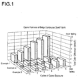
procedure and the beige shade. The color change after ozone exposure
is given in Table 2 and FIG. 1
Example 2 (Invention) - 10 % Nylon 6,12 Sheath
Simulated Continuous Dyeing - Acid Beige Dye
Using the equipment and settings of Example 1 the nylon 6 in the
second extruder is replaced with nylon 6,12 ("N6,12") (poly(hexamethylene
dodecanediamide)) (Vestamid® D16 available from Creanova,
Somerset, NJ). A 58 filament yarn is produced and has the
properties summarized in Table 1.
The yarn is knitted on a circular weft knitting machine. The knit
tube is dyed using the simulated continuous dye procedure using
the beige shade formulation. In a first attempt to dye this yarn
using the same formulation as used in Example 1 (comparative) the
color is noticeably lighter than that achieved in Example 1.
Accordingly, the dyeing procedure is modified by doubling the
concentration of dyes (not auxiliaries) and lowering the pH to
6.0 with acetic acid. The time of steaming is doubled to 8 minutes.
The resulting knitted tube has a similar depth of color to
that achieved in Example 1. This tube (not the first attempt) is
exposed to ozone and the color change after ozone exposure is given
in Table 2 and FIG. 1.
Example 3 (Invention) 5 % Nylon 6,12 Sheath
Simulated Continuous Dyeing - Acid Beige Dye
Using the equipment and settings of Example 1 the nylon 6 in the
second extruder is replaced with nylon 6,12. The metering pumps
supplying the spin pack are adjusted to provide 5% by weight of
the nylon 6,12 from the second extruder. A 58 filament yarn is
produced and has the properties summarized in Table 1.
The yarn is knitted into a tube on a circular weft knitting machine.
This tube is dyed using the simulated continuous dye procedure
given above using the beige shade formulation. Because the
first attempt to dye this yarn using the same formulation as used
in Example 1 (comparative) results in a noticeably lighter color
than that achieved in Example 1, the modified dyeing procedure of
Example 2 is followed. The resulting knitted tube has a similar
depth of color to that achieved in Example 1. This tube (not the
first attempt) is exposed to ozone and the color change after
ozone exposure is given in Table 2 and FIG. 1.
| Properties of Yarns from Examples 1-3. |
| Example | Total Linear Density (de-nier) | Tenac-ity (g/den) | Elonga-tion (%) | Work to Break (g/cm) | Boiling Water Shrinkage (%) | Filament Modifica-tion Ratio |
| 1 | 1260 | 2.82 | 36.1 | 4452 | 9.1 | 2.52 |
| 2 | 1282 | 2.88 | 37.4 | 4726 | 7.3 | 2.70 |
| 3 | 1257 | 2.83 | 36.9 | 4197 | 6.3 | 2.62 |
| Acid Beige Dye (ΔE*) |
| | Ozone Cycles |
| | | 1 | 2 | 3 | 4 | 5 | 6 |
| Ex 1 | 100% N6 | 2.2 | 2.8 | 3.9 | 5.2 | 5.9 | 6.7 |
| Ex 2 | 10% N6,12 Sheath | 0.5 | 0.8 | 0.6 | 0.8 | 1.2 | 0.9 |
| Ex 3 | 5% N6,12 Sheath | 0.6 | 0.6 | 0.7 | 1.1 | 1.6 | 1.8 |
A knit tube of yarn from Example 1 is dyed using the simulated
continuous dye procedure given above using the gray shade formulation.
The color change after ozone exposure is given in Table 3
and FIG. 2.
Example 5 (Invention) 10% N6,12 Sheath
Simulated Continuous Dyeing - Acid Gray Dye
A knit tube of yarn from Example 2 is dyed using the simulated
continuous dye procedure given above using the gray shade formulation.
The color change after ozone exposure is given in Table 3
and FIG. 2.
Example 6 (Invention) 5% N6,12
Simulated Continuous Dyeing - Acid Gray Dye
A knit tube of yarn from Example 3 is dyed using the simulated
continuous dye procedure given above using the gray shade formulation.
The color change after ozone exposure is given in Table 3
and Figure 5.
| Acid Gray Dye (ΔE*) |
| | Ozone Cycles |
| | | 1 | 2 | 3 | 4 | 5 | 6 |
| Ex 4 | 100% N6 | 1.2 | 1.7 | 2.9 | 4.0 | 4.2 | 5.7 |
| Ex 5 | 10% N6,12 Sheath | 0.8 | 0.9 | 1.0 | 1.0 | 1.5 | 1.2 |
| Ex 6 | 5% N6,12 Sheath | 1.2 | 1.4 | 2.2 | 1.9 | 1.6 | 2.2 |
A knit tube of yarn from Example 1 is dyed using the simulated
continuous dye procedure given above using the blue-gray shade
formulation. The color change after ozone exposure is given in
Table 4 and FIG. 3.
Example 8 (Invention) 10% N6,12 Sheath
Simulated Continuous Dyeing - Acid Blue-Gray Dye
A knit tube of yarn from Example 2 is dyed using the simulated
continuous dye procedure given above using the blue-gray shade
formulation. The color change after ozone exposure is given in
Table 4 and FIG. 3.
Example 9 (Invention) 5% N6,12 Sheath
Simulated Continuous Dyeing - Acid Blue-Gray Dye
A knit tube of yarn from Example 3 is dyed using the simulated
continuous dye procedure given above using the blue gray shade
formulation. The color change after ozone exposure is given in
Table 4 and FIG.3.
| Acid Blue-Gray Dye (ΔE*) |
| | Ozone Cycles |
| | | 1 | 2 | 3 | 4 | 5 | 6 |
| Ex 7 | 100% N6 | 1.6 | 2.7 | 4.6 | 5.7 | 6.1 | 7.6 |
| Ex 8 | 10% N6,12 Sheath | 0.5 | 1.7 | 0.6 | 1.8 | 1.3 | 2.7 |
| Ex 9 | 5% N6,12 Sheath | 0.8 | 0.9 | 1.0 | 1.0 | 1.5 | 1.2 |
A knit tube of yarn from Example 1 is dyed using the simulated
continuous dye procedure given above using the green shade formulation.
The color change after ozone exposure is given in Table 5
and FIG. 4.
Example 11 (Invention) 10% N6,12 Sheath
Simulated Continuous Dyeing - Acid Green Dye
A knit tube of yarn from Example 2 is dyed using the simulated
continuous dye procedure given above using the green shade formulation.
Because the first attempt at dyeing results in a shade
that is noticeably lighter than that of Example 10. The dyeing
procedure is modified as described in Example 2 and the resulting
dyed knitted tube has a very similar color to that of Example 10.
The color change after ozone exposure is given in Table 5 and
FIG. 4.
Example 12 (Invention) 5% N6,12 Sheath
Simulated Continuous Dyeing - Acid Green Dye
A knit tube of yarn from Example 3 is dyed using the simulated
continuous dye procedure given above using the green shade formulation.
Because the first attempt at dyeing results in a shade
that is noticeably lighter than that of Example 10, the dyeing
procedure is modified as described in Example 2 and the resulting
dyed knitted tube has a very similar color to that of Example 10.
The color change after ozone exposure is given in Table 5 and
FIG. 4.
| Acid Green Dye (ΔE*) |
| | Ozone Cycles |
| | | 1 | 2 | 3 | 4 | 5 | 6 |
| Ex 10 | 100% N6 | 1.7 | 2.9 | 3.6 | 4.8 | 5.6 | 6.7 |
| Ex 11 | 10% N6,12 Sheath | 0.7 | 1.1 | 0.8 | 1.1 | 1.0 | 1.4 |
| Ex 12 | 5% N6,12 Sheath | 1.0 | 0.8 | 1.5 | 1.7 | 2.0 | 1.6 |
A knit tube of yarn from Example 1 is dyed using the simulated
continuous dye procedure given above using the disperse blue formulation.
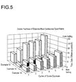
The color change after ozone exposure is given in Table
6 and FIG. 5.
Example 14 (Comparative) 10% N6,12 Sheath
Simulated Continuous Dyeing - Disperse Blue Dye
A knit tube of yarn from Example 2 is dyed using the simulated
continuous dye procedure given above using the disperse blue formulation.
The color change after ozone exposure is given in Table
6 and FIG 5.
Example 15 (Comparative) 5% N6,12 Sheath
Simulated Continuous Dyeing - Disperse Blue Dye
A knit tube of yarn from Example 3 is dyed using the simulated
continuous dye procedure given above using the disperse blue
formulation. The color change after ozone exposure is given in
Table 6 and FIG 5.
| Blue Disperse Dye (ΔE*) |
| | Ozone Cycles |
| | | 1 | 2 | 3 | 4 | 5 | 6 |
| Ex 13 | 100% N6 | 11.0 | 14.4 | 20.7 | 22.1 | 23.1 | 28.3 |
| Ex 14 | 10% N6,12 Sheath | 2.9 | 4.3 | 6.1 | 7.0 | 7.1 | 9.1 |
| Ex 15 | 5% N6,12 Sheath | 3.8 | 5.8 | 8.6 | 10.1 | 11.8 | 15.0 |
Yarn prepared as in Example 1 (except that it is not first knitted
into a tube) is cabled to a twist level of 5 twists per inch
(197 twists/meter) on a Volkmann cable twister and heatset. The
yarn is then knitted on a circular weft knitting machine and dyed
using the exhaust dye procedure given above using the beige acid
dyes formulation. The color change after ozone exposure is given
in Table 7 and FIG. 6.
Example 17 (Invention) 10% N6,12 Sheath
Heatset and Exhaust Dyed with Acid Beige Dye
The yarn from Example 2 is cabled, heatset, knit into a tube and
exhaust dyed to a beige shade as described in Example 16. The color
change after ozone exposure is given in Table 7 and FIG. 6.
Example 18 (Invention) 5% N6,12 Sheath
Heatset and Exhaust Dyed with Acid Beige Dye
The yarn from Example 3 is cabled, heatset, knit into a tube and
exhaust dyed to a beige shade as described in Example 16. The color
change after ozone exposure is given in Table 7 and FIG. 6.
| Heatset - Exhaust Dyed Beige (ΔE*) |
| | Ozone Cycles |
| | | 1 | 2 | 3 | 4 | 5 | 6 |
| Ex 16 | 100% N6 | 1.5 | 2.8 | 4.1 | 5.6 | 5.4 | 8.1 |
| Ex 17 | 10% N6,12 Sheath | 0.5 | 0.4 | 0.8 | 0.6 | 0.9 | 1.0 |
| Ex 18 | 5% N6,12 Sheath | 1.1 | 0.8 | 1.2 | 1.0 | 1.0 | 1.0 |
The yarn from Example 1 is cabled, heatset, knit into a tube as
described in Example 16 and exhaust dyed to a gray shade. The color
change after ozone exposure is given in Table 8 and FIG 7.
Example 20 (Invention) 10% N6,12 Sheath
Heatset and Exhaust Dyed with Acid Gray Dye
The yarn from Example 2 is cabled, heatset, knit into a tube as
described in Example 16 and exhaust dyed to a gray shade. The color
change after ozone exposure is given in Table 8 and FIG. 7.
Example 21 (Invention) 5% N6
Heatset and Exhaust Dyed with Acid Gray Dye
The yarn from Example 3 is cabled, heatset, knit into a tube as
described in Example 16 and exhaust dyed to a gray shade. The color
change after ozone exposure is given in Table 8 and FIG. 7.
| Heatset - Exhaust Dyed Gray (ΔE*) |
| | Ozone Cycles |
| | | 1 | 2 | 3 | 4 | 5 | 6 |
| Ex 19 | 100% N6 | 1.7 | 3.6 | 6.1 | 7.1 | 8.3 | 10.7 |
| Ex 20 | 10% N6,12 Sheath | 0.6 | 0.4 | 1.1 | 0.9 | 1.1 | 1.4 |
| Ex 21 | 5% N6,12 Sheath | 0.6 | 0.3 | 1.0 | 0.8 | 0.9 | 1.3 |
The yarn from Example 1 is cabled, heatset, knit into a tube as
described in Example 16 and exhaust dyed to a blue-gray shade.
The color change after ozone exposure is given in Table 9 and
FIG. 8.
Example 23 (Invention) 10% N6,12 Sheath
Heatset and Exhaust Dyed with Acid Blue-Gray Dye
The yarn from Example 2 is cabled, heatset, knit into a tube as
described in Example 16 and exhaust dyed to a blue-gray shade.
The color change after ozone exposure is given in Table 9 and
FIG. 8.
Example 24 (Invention) 5% N6,12 Sheath
Heatset and Exhaust Dyed with Acid Blue-Gray
The yarn from Example 3 is cabled, heatset, knit into a tube as
described in Example 16 and exhaust dyed to a gray shade. The color
change after ozone exposure is given in Table 9 and FIG. 8.
| Heatset - Exhaust Dyed Blue-Gray (ΔE*) |
| | Ozone Cycles |
| | | 1 | 2 | 3 | 4 | 5 | 6 |
| Ex 22 | 100% N6 | 2.0 | 4.3 | 5.6 | 7.6 | 8.7 | 10.7 |
| Ex 23 | 10% N6,12 Sheath | 0.3 | 0.4 | 1.1 | 1.1 | 1.4 | 1.2 |
| Ex 24 | 5% N6,12 Sheath | 0.4 | 0.5 | 0.9 | 0.8 | 0.9 | 0.7 |
Heatset and Exhaust Dyed with Acid Green Dye
The yarn from Example 1 is cabled, heatset, knit into a tube as
described in Example 16 and exhaust dyed to a green shade. The
color change after ozone exposure is given in Table 10 and FIG.
9.
Example 26 (Invention) 10% N6,12 Sheath
Heatset and Exhaust Dyed with Acid Green Dye
Yarn from Example 2 is cabled, heatset, knitted into a tube as
described in Example 16. The knit tube is exhaust dyed to a green
shade using the exhaust dye procedure except that, because in a
first attempt to dye this yarn using the same formulation as used
in Example 25 the color is noticeably lighter than that achieved
in Example 25, the dyeing procedure is modified by increasing the
length of the dyeing procedure from 30 minutes (1800 seconds) at
95°C to 60 minutes (3600 seconds) at 95°C. A slight color difference
from that of Example 25 is still noted. The color change
after ozone exposure is given in Table 10 and FIG. 9.
Example 27 (Invention) 5% N6,12 Sheath
Heatset and Exhaust Dyed with Acid Green Dye
Yarn from Example 3 is cabled, heatset, knitted into a tube as
described in Example 16. The knit tube is exhaust dyed to a green
shade using the exhaust dye procedure except that, because in a
first attempt to dye this yarn using the same formulation as used
in Example 25 the color is noticeably lighter than that achieved
in Example 25, the dyeing procedure is modified as described in
Example 26. A slight color difference from that of Example 25 is
still noted. The color change after ozone exposure is given in
Table 10 and FIG. 9.
| Heatset - Exhaust Dyed Green (ΔE*) |
| | Ozone Cycles |
| | | 1 | 2 | 3 | 4 | 5 | 6 |
| Ex 25 | 100% N6 | 1.1 | 2.4 | 3.4 | 4.2 | 4.8 | 5.8 |
| Ex 26 | 10% N6,12 Sheath | 0.2 | 0.5 | 1.0 | 1.1 | 1.2 | 1.1 |
| Ex 27 | 5% N6,12 Sheath | 0.8 | 1.0 | 1.6 | 0.7 | 0.9 | 1.1 |
The yarn from Example 1 is cabled, heatset, knit into a tube as
described in Example 16. The tube is exhaust dyed with the disperse
blue dye formulation. The color change after ozone exposure
is given in Table 11 and FIG. 10.
Example 29 (Comparative) 10% N6,12 Sheat.
Heatset and Exhaust Dyed with Disperse Blue Dye
The yarn from Example 2 is cabled, heatset, knit into a tube as
described in Example 16. The tube is exhaust dyed with the disperse
blue dye formulation. The color change after ozone exposure
is given in Table 11 and FIG. 10.
Example 30(Comparative) 5% N6,12 Sheath
Heatset and Exhaust Dyed with Disperse Blue Dye
The yarn from Example 3 is cabled, heatset, knit into a tube as
described in Example 16. The tube is exhaust dyed with the disperse
blue dye formulation. The color change after ozone exposure
is given in Table 11 and FIG. 10.
| Heatset - Exhaust Dyed - Disperse Blue Dye (ΔE*) |
| | Ozone Cycles |
| | | 1 | 2 | 3 | 4 | 5 | 6 |
| Ex 28 | 100% N6 | 20.2 | 32.8 | 41.4 | 42.0 | 44.7 | 46.6 |
| Ex 29 | 10% N6 Sheath | 3.3 | 6.3 | 10.4 | 10.9 | 13.7 | 14.1 |
| Ex 30 | 5% N6 Sheath | 2.3 | 4.3 | 5.4 | 6.8 | 7.9 | 8.5 |
Knit tubes made as described in Examples 1-3 before dyeing, are
subjected to the red drink stain test and the coffee stain test.
Similarly, knit tubes dyed blue-gray as described in Examples 7-9
are subjected to red drink and coffee stain testing. The results
are presented in Table 12.
| Stain Testing (ΔE*) |
| | Undyed Red Drink | Dyed Red Drink | Undyed Coffee | Dyed Coffee |
| 100% N6 | 60.1 | 20.0 | 28.7 | 1.2 |
| 10% N6,12 Sheath | 10.9 | 0.9 | 16.8 | 0.2 |
| 5% N6,12 Sheath | 13.2 | 0.8 | 19.9 | 0.2 |
On a pilot scale spinning machine, a 100% N6 yarn is extruded
from a single screw extruder at a melt temperature of 265°C into a
spinneret to produce 14 round filaments. The yarn is accumulated
on a winder at approximately 400 meters/minute with the godets
operated with a very small (less than 10 m/min) speed differential,
such that the yarn is undrawn.
In a separate step this yarn is heated and drawn 3.1 times its
original length on a drawknitting machine. The final linear
density is approximately 252 denier. Knit tubes are formed from
the yarn and these are dyed to beige, gray, blue-gray and green
using the Exhaust Dye Procedure.
The color of the original tubes are measured according to the
CIEL*a*b* system and the tubes are exposed to 1, 2, 3, 4, 5 and 6
cycles of ozone. The results are presented in Table 13.
Example 32B - N6,12
N6,12 is extruded and formed into yarn as in Example 32A except
that the first godet is slowed such that a draw ratio of 2:1 is
induced in the yarn. The first godet runs at 200 m/min and the
second at 400 m/min. This drawing step is required because the
undrawn yarn does not form a stable package. The yarn relaxes on
the package and cannot be processed.
In a separate step this yarn is knitted (bypassing the heating
and drawing steps) on the same drawknitter as in Example 32A but
without further drawing. Thus, the final linear density is approximately
391. Knit tubes are formed from the yarn and these are
dyed to beige, gray, blue-gray and green using the Exhaust Dye
Procedure.
The color of the original tubes are measured according to the
CIEL*a*b* system and the tubes are exposed to ozone. The results
are presented in Table 13.
The Delta E* and Delta L* values compare the two similarly dyed
knitted fabrics. The greater the Delta E* value the greater the
difference in the appearance of the two shades. The Delta L* value
is of particular interest here because this is a measure of
the change in lightness/darkness of the two shades. Delta L* is
calculated as follows: L*sample - L*standard = Delta L*. For the
values in the above table, a positive value for each of the
Example 32B samples indicates the color is lighter, hence has
dyed less. For all of the acid dyes examined, the fabrics made
from nylon 6,12 did dye, but to a much smaller amount than those
from Example A. Such a drastic reduction in color yield would be
unacceptable under current carpet industry expectations for yarn
dyeability.
Example 33: Sheath Polymer Stain Screening
Polymer was charged into an extruder and extruded into mono-component
trilobal filaments at about 270°C. The extruded filaments
were cooled in air and lubricated with spin finish. Yarns comprised
of the filaments were taken up on a winder at speed of about
900 m/min. The yarns were drawn prior to winding and the draw ratio
was around 3. The final denier of the yarns with trilobal
cross-section is 826 denier/64 filaments. The amino end group
(AEG) content and stain test results are summarized in Table 14
below.
| | AEG
(meq/kg) | Food Red-17
Stain Test
(Delta E) | Coffee Stain
Test (Delta E) |
| Nylon-6 | 45.3 | 50.81 | 14.74 |
| Nylon-6,12 Homopoly-mer | 3.4 | 3.69 | 3.44 |
| Nylon-6,12 Copolymer | 48.0 | 57.17 | 18.78 |
| Nylon-6,12 Copolymer w/reduced AEG | 12.8 | 49.01 | 18.59 |
As can be seen from the data above, the nylon-6,12 homopolymer
with low AEG content is an exemplary polymer suitable for the
sheath component in sheath/core filaments due to its minimal
staining with Food Red 17 and coffee.
Example 34: Dyed Sheath Core Filament
Yarn formed of individual trilobal sheath/core filaments was spun
with a bicomponent melt-spinning apparatus that keeps the molten
sheath polymer stream separate from the core polymer stream until
just before entering the spinneret hole capillary. The core polymer
of the trilobal filaments was cationic dyeable nylon 6 polymer,
BS 600C (BASF Corporation), and the sheath polymer was VE-STAMID®
D16 nylon 6/12 commercially obtained from Creanova. The
core polymer contained 0.3% TiO2 while the sheath contained no additives.
The yarn is spun at 275°C through a symmetrical trilobal
capillary shape and cooled by a stream of cool quench air blowing
across the filaments. The yarn sample was taken from within the
cooling cabinet before the yarn was drawn or textured. The polymer
pumps were set to deliver the sheath polymer at 15% (by
weight) and the core polymer at 85% by weight.
The yarn was dyed along with production hoselegs with a laboratory
dye procedure, as follows:
- Dyeing Apparatus =
- Hunter Dye Beck
- Dyestuff =
- Sevron Red YCN (0.4% owf)
- Dyebath Auxiliaries =
- Luratex (1.0% owf)
Intralan Salt HA (0.15% owf)
- Liquor Ratio =
- 40 to 1
- pH =
- 6.0 to 6.2 (Adjust with trisodium
phosphate (TSP) or citric acid)
- Dyeing =
- at boil for 30 minutes
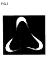
A photomicrograph of a cross-section of an exemplary dyed sheath/core
filament is shown in accompanying FIG. 6. As can be seen,
the dye in the dye bath physically penetrated the sheath so as to
impart a dyed color to the core, while leaving the sheath substantially
undyed. The color of the dyed core polymer was thus
visibly perceptible through the substantially undyed sheath polymer
providing a color dyed appearance to the yarn overall while
retaining the stain resistance attributable to the sheath polymer.
While the invention has been described in connection with what is
presently considered to be the most practical and preferred embodiment,
it is to be understood that the invention is not to be
limited to the disclosed embodiment, but on the contrary, is intended
to cover various modifications and equivalent arrangements
included within the spirit and scope of the appended claims.