EP1254779A2 - Imaging apparatus and imaging drum having material clamp - Google Patents
Imaging apparatus and imaging drum having material clamp Download PDFInfo
- Publication number
- EP1254779A2 EP1254779A2 EP02076534A EP02076534A EP1254779A2 EP 1254779 A2 EP1254779 A2 EP 1254779A2 EP 02076534 A EP02076534 A EP 02076534A EP 02076534 A EP02076534 A EP 02076534A EP 1254779 A2 EP1254779 A2 EP 1254779A2
- Authority
- EP
- European Patent Office
- Prior art keywords
- drum
- slide
- magnet
- imaging
- imaging drum
- Prior art date
- Legal status (The legal status is an assumption and is not a legal conclusion. Google has not performed a legal analysis and makes no representation as to the accuracy of the status listed.)
- Withdrawn
Links
- 239000000463 material Substances 0.000 title claims abstract description 149
- 238000003384 imaging method Methods 0.000 title claims abstract description 113
- 230000005291 magnetic effect Effects 0.000 claims description 90
- 230000007246 mechanism Effects 0.000 description 8
- XEEYBQQBJWHFJM-UHFFFAOYSA-N Iron Chemical compound [Fe] XEEYBQQBJWHFJM-UHFFFAOYSA-N 0.000 description 6
- 230000007704 transition Effects 0.000 description 6
- 230000002441 reversible effect Effects 0.000 description 5
- 229910000831 Steel Inorganic materials 0.000 description 3
- 229910052742 iron Inorganic materials 0.000 description 3
- 239000010959 steel Substances 0.000 description 3
- 238000003780 insertion Methods 0.000 description 2
- 230000037431 insertion Effects 0.000 description 2
- 238000001931 thermography Methods 0.000 description 2
- 241000237519 Bivalvia Species 0.000 description 1
- XAGFODPZIPBFFR-UHFFFAOYSA-N aluminium Chemical compound [Al] XAGFODPZIPBFFR-UHFFFAOYSA-N 0.000 description 1
- 229910052782 aluminium Inorganic materials 0.000 description 1
- 230000002238 attenuated effect Effects 0.000 description 1
- 230000009286 beneficial effect Effects 0.000 description 1
- 230000015572 biosynthetic process Effects 0.000 description 1
- 235000020639 clam Nutrition 0.000 description 1
- 230000007423 decrease Effects 0.000 description 1
- 230000009977 dual effect Effects 0.000 description 1
- 230000005611 electricity Effects 0.000 description 1
- 230000005672 electromagnetic field Effects 0.000 description 1
- 230000005294 ferromagnetic effect Effects 0.000 description 1
- 239000003302 ferromagnetic material Substances 0.000 description 1
- 239000000696 magnetic material Substances 0.000 description 1
- 238000000926 separation method Methods 0.000 description 1
- 239000000126 substance Substances 0.000 description 1
- 239000000758 substrate Substances 0.000 description 1
- 230000000153 supplemental effect Effects 0.000 description 1
- -1 thermal media Substances 0.000 description 1
Images








Classifications
-
- B—PERFORMING OPERATIONS; TRANSPORTING
- B41—PRINTING; LINING MACHINES; TYPEWRITERS; STAMPS
- B41J—TYPEWRITERS; SELECTIVE PRINTING MECHANISMS, i.e. MECHANISMS PRINTING OTHERWISE THAN FROM A FORME; CORRECTION OF TYPOGRAPHICAL ERRORS
- B41J13/00—Devices or arrangements of selective printing mechanisms, e.g. ink-jet printers or thermal printers, specially adapted for supporting or handling copy material in short lengths, e.g. sheets
- B41J13/10—Sheet holders, retainers, movable guides, or stationary guides
- B41J13/22—Clamps or grippers
- B41J13/223—Clamps or grippers on rotatable drums
Definitions
- This invention relates to an imaging apparatus having an imaging drum to movably position sheet material such as thermal imaging material, dye donor sheets and direct writing plates during image formation. More specifically the present invention relates to mechanisms for loading, holding and releasing sheet material on an imaging drum.
- a sheet material such as a thermal media or a plate.
- the sheet material is secured to an imaging drum and the imaging drum is rotated while a print head forms an image on the material. This can be done by transferring dye or ink to a sheet of material or by modifying the sheet of material.
- the task of attaching sheet material to the vacuum imaging drum is often rigorous because it requires precise positioning of the sheet material on the imaging drum. Once that sheet material is properly positioned on the drum it is necessary to hold the sheet material in place during imaging operations.
- Various mechanisms are known in the art to help secure sheet material such as thermal media, dye donor materials and direct write plates to an imaging drum.
- magnets are attached on top of the media or direct write plates and the force of the magnetic attraction between the magnet and the outer surface holds the media or direct write plates in contact with the drum.
- the magnetic attraction between the magnet and the outer surface must provide sufficient magnetic attraction to resist the centrifugal force of the drum as it rotates. Because the centrifugal force increases with drum rotation speed, it is necessary to use more powerful magnets to secure the media to the drum in order to withstand the centrifugal force created by increased rotational speed. It will be recognized that a point is reached where it becomes impractical to use magnets that have sufficient attractive force to withstand the aforementioned centrifugal force.
- a dual chamber vacuum imaging drum is used to help controllably position the dye donor media and the thermal media on the surface of an imaging drum.
- One chamber applies vacuum that holds the lead edge of the dye donor material.
- Another chamber controls vacuum which holds the trail edge of the thermal print media to the vacuum in imaging drum.
- Unloading the dye donor material or the thermal print media requires the removal of vacuum from the same chamber so that in edge of the thermal print media or the dye donor material are freed in project out from the surface of the vacuum imaging drum.
- the image processing apparatus deposits an articulating skive into the path of the free edge of the donor material to lift the edge further and feed the dye donor material to a waist bin or output tray.
- an imaging apparatus for forming images on sheet material.
- the imaging assembly comprises a print head for forming images on the sheets and an imaging drum having an outer surface.
- a motor is also provided for rotating the imaging drum.
- a material clamp is mounted to the imaging drum having a retainer positioning a retaining surface radially outward of the outer surface and forming a space therebetween.
- a slide is movable within the space between an outer radial position where outward radial movement of the slide is blocked by the retaining surface and an inner radial position distant from the retaining surface.
- a magnet is provided having a magnetic field biases the slide toward the outer radial position. Rotation of the drum creates centrifugal force that further biases the slide toward the outer radial position.
- an imaging drum assembly for use in an imaging apparatus for forming images on sheet material.
- the imaging drum assembly comprises a rotatable imaging drum having an outer surface adapted to attract material to the drum.
- a material clamp mounted to the drum having a retainer positioning a retaining surface radially outward of the outer surface and forming a space therebetween.
- a slide is movable within the space between an outer radial position where outward radial movement of the slide is blocked by the retaining surface and an inner radial position distant from the retaining surface. Rotation of the drum creates centrifugal force that biases the slide toward the outer radial position.
- an imaging drum assembly for use in an imaging apparatus for forming images on sheet material.
- the imaging drum assembly comprises a rotatable imaging drum having an outer surface adapted to attract sheet material to the imaging drum.
- a material clamp is mounted to the drum and has a retainer positioning a retaining surface radially outward of the outer surface and forming a space therebetween.
- a slide is movable positioned within the space between an outer radial position where outward radial movement of the slide is blocked by the retaining surface and an inner radial position distant from the retaining surface.
- a biasing member urges the slide toward the outer radial position.
- the image processing apparatus 20 is comprised of a housing 22, sheet material supply assembly 24; a print head 26; an imaging drum 28, a motor 30 and an output area 34.
- the image processing apparatus 20 is arranged to form an image on sheet material 36.
- image processing apparatus 20 comprises transporting sheet material 36 to imaging drum 28, registering sheet material 36 on drum 28, wrapping sheet material 36 around drum 28, and securing sheet material 36 on imaging drum 28.
- motor 30 rotates drum 28 to move sheet material 36 past print head 26.
- Print head 26 forms an image on sheet material 36.
- sheet material 36 is transported to output area 34.
- Sheet material 36 can comprise a thermal transfer media, a dye donor sheet, a direct write plate or other forms of sheet material on which images can be formed.
- Imaging drum 28 comprises a cylindrical shaped imaging drum outer surface 38, which can, for example, be manufactured from a length of extruded aluminum tubing.
- imaging drum 28 is adapted to use a vacuum to assist in loading, holding, and unloading the sheet material 36.
- vacuum it is not necessary to use vacuum to provide such assistance.
- imaging drum 28 can be adapted to use other attractive means such as electrostatic attraction or other attractive forces known in the art to assist during loading, holding and unloading sheet material.
- imaging drum 28 of the present invention can be used without such assistance simply by holding sheet material 36 using a material clamp 50 to be disclosed hereinafter.
- imaging drum 28 is shown provided with a plurality of vacuum grooves 40 on outer surface 38 of imaging drum 28 and vacuum holes 42 which extend through the vacuum drum outer surface 38.
- Vacuum holes 42 and vacuum grooves 40 allow a vacuum to be applied through a hollowed-out interior portion (not shown) of imaging drum 28 for supporting and maintaining the position of sheet material 36 on imaging drum 28.
- Vacuum imaging drum 28 has two ends closed by a vacuum end plate 44, and a drive end plate (not shown).
- the drive end plate is provided with a centrally disposed drive spindle 46, which extends outwardly.
- Vacuum end plate 44 is provided with a centrally disposed vacuum spindle 48, which extends outwardly therefrom.
- Drive spindle 46 is connected to a motor 30.
- Motor 30 is fixed to housing 22 and provides a reversible, variable drive motor for rotating imaging drum 28.
- Vacuum spindle 48 is provided with a central vacuum opening 49. Vacuum opening 49 is connected to a vacuum blower (not shown) which provides the vacuum imaging drum 28 during the loading, scanning and unloading of sheet media 36.
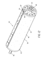
- Figs. 2a and 2b also show a retainer 52 fixed to imaging drum 28.
- Retainer 52 includes a boss 54 and a retaining surface 56.
- Boss 54 is fixed to drum 28 and extends radially outward of outer surface 38.
- Boss 54 holds retaining surface 56 in a position radially outward of outer surface 38.
- Fig. 3a shows a partial cross section view of drum 28 and material clamp 50.
- imaging drum 28 also comprises a recess 58 in outer surface 38.
- Retaining surface 56 is positioned radially outward of recesses 58.
- Recess 58 has an outer end 60 defining an opening 62 in outer surface 38 and an inner end 64 separated from surface 38.
- a slide 66 is slidable in recess 58.
- FIG. 3a shows the material clamp 50 with sheet material 36 is loaded between outer surface 38 and retaining surface 56 (Fig. 3a).
- vacuum is applied to hollowed-out interior portion 29 of drum 28 and serves to hold sheet material 36 to outer surface 38.
- centrifugal force biases slide 66 toward the outer radial position. Slide 66 advances to contact sheet material 36 and to clamp sheet material 36 against retaining surface 56 (Fig. 3b).
- the clamping force exerted by slide 66 and retaining surface 56 increases as the speed of rotation of drum 28 is increased. In this manner, it is possible to rotate imaging drum 28 at a higher speed or to reduce the amount of energy that must be expended by the vacuum during operation.
- a material clamp 50 can be used to load, hold and unload sheet media 36 from the outer surface 38 of drum 28 without the need to adapt outer surface 28 to attract sheet media 36.
- slide 66 is biased toward the outward radial position. The motion of slide 66 is stopped at the outer radial position by engagement with retaining surface 56.
- retaining surface 56 When sheet material 36 is to be mounted to drum 28, a portion of sheet 36 is disposed between slide 66 and retaining surface 56.
- the bias acting on slide 66 provides a clamping force to hold sheet material 36 in material clamp 50.
- Slide 66 can be biased mechanically using spring, pneumatic, thermal or electro-mechanical motors or solenoids.
- slide 66 has a first end 68 having a first magnetic polarity and a second end 70 having a second magnetic polarity.
- the magnetic polarities of slide 66 can be created by integrating component magnets (not shown) into slide 66 or by magnetizing slide 66.
- first end 68 is associated with a magnetic North pole N while second end 70 is associated with a magnetic South pole S.
- a drum magnet 72 is positioned proximate to inner end 64.
- drum magnet 72 also has a North magnetic pole N and a South magnetic pole S.
- the South magnetic pole S of drum magnet 72 is positioned to confront the South magnetic poles of slide 66.
- drum magnet 72 repels slide 66. This biases slide 66 away from inner end 64 toward retaining surface 56.
- first end 68 of slide 66 comprises an optional tapered lead-in surface to facilitate loading of sheet material 36.
- Fig. 4b shows the operation of this embodiment when sheet material 36 is installed on imaging drum 28.
- the sheet material 36 is fixed in material clamp 50 by inserting the sheet material 36 between outer surface 38 and retaining surface 56. This brings the sheet material 36 into contact with the first end 68 and causes slide 66 to be displaced into recess 58. This also causes the second end 70 of slide 66 to come into closer proximity to drum magnet 72. It will be appreciated that the magnetic repulsion between the drum magnet 72 and slide 66 increases as the separation between the second end 70 of slide 66 and drum magnet 72 decreases.
- retaining surface 56 comprises a material that is magnetically attractive to the first magnetic polarity of first end 68 of slide 66.
- This magnetically attractive material can be comprised of a ferro-magnetic material such as an iron or steel material and can be comprised of a magnet having a magnetic polarity that is opposite to the magnetic polarity of the first end 68 of slide 66 and therefore attractive to slide 66. In the embodiment of Figs. 4a - 4c, this provides an additional biasing force to attract the slide 66 toward retaining surface 56.
- drum 28 and material clamp 50 are arranged to use both centrifugal force and magnetic force to bias slide 66.
- Figs 5a and 5b One example of such an embodiment is shown in Figs 5a and 5b.
- slide 66 is arranged for movement in a manner that is consistent with the centrifugal force generated by rotation of drum 28. Slide 66 also generates a magnetic field. This magnetic field is repelled by the magnetic field of drum magnet 72 to provide a magnetic force to bias slide 66 in the manner that is described above.
- the first clamping force is the material clamping force that operates as described above.
- the second clamping force comes into being when motor 30 turns drum 28 and is generated by centrifugal force acting against slide 66.
- Slide 66 is free to move toward and away from the center of drum 28.
- material clamp 50 automatically increases the clamping force acting on the sheet material 36 with increases in the speed of rotation of drum 28.
- magnetic drum 28 It may be beneficial to provide magnetic drum 28 with a material clamp 50 structure that will allow material clamp 50 to be operated in a "close” state to hold sheet material in material clamp 50 and in an "open” state to facilitate insertion and removal of sheet material 38 in material clamp 50.
- drum 38 of the present invention has a material clamp 50 that is transitioned from an "open” state to a "close” state by varying the intensity of the magnetic field that acts against magnetic slide 66 between a high level associated with the "close” state and a low level that is associated with the "open” state.
- the intensity of the magnetic field that acts against the second pole of slide 66 is sufficient to fully bias slide 66 and to cause material clamp 50 to operate as described above.
- the intensity of the magnetic field that acts against the second pole of slide 66 is substantially attenuated or eliminated.
- Figs. 6a and 6b show an embodiment of a drum 28 of the present invention having a clamp 50 with a mechanical structure for attenuating the magnetic bias exerted by drum magnet 72 against slide 66 in order to transition clamp 50 from the "open” state to the "close” state.
- slide 66 is selectively repelled and attracted mechanically by varying the polarity of the magnetic field that acts against the second magnetic pole of slide 66. This is accomplished by physically moving the drum magnet 72 from a first position proximate to inner end 64 to a second position that is separate from the inner end 64.
- drum magnet 72 is positioned in the first position when material clamp 24 is in the "open” state, and drum magnet 72 is moved to the second position when material clamp 24 is in the "close” state.
- drum magnet 72 has a first magnetic pole that repels slide 66 at first end 73 and a second magnetic pole at second end 75.
- Drum magnet 72 is fixed to rotatable cam 74.
- cam 74 positions first end 73 of drum magnet 72 proximate to inner end 64. This biases slide 66 away from first end 66 and toward retaining surface 56.
- cam 74 is rotated to a position, shown in Fig. 6b, wherein first end 73 of drum magnet 72 is separated from inner end 64.
- Fig. 6b shows first end 73 of drum magnet 72 is separated from inner end 64.
- drum magnet 72 comprises an electromagnet and imaging apparatus 10 further comprises an electromagnet power supply 71.
- Electromagnet power supply 71 is electrically connected to the electromagnet and supplies a reversible flow of current to the electromagnet.
- the intensity of the magnetic field to which slide 66 is exposed is defined by the intensity of current flow through the electromagnet. Accordingly, when it is desired to place material clamp 50 in the "open” state, the flow of electric current through the electromagnet is stopped or substantially reduced.
- the electromagnetic power supply causes current to flow in through the electromagnet. This causes drum magnet 72 to generate a magnetic field which, in turn, biases slide 66 toward retaining surface 56.
- Material clamp 50 can also be transitioned from an "open” state to a "close” state by varying the he polarity of the magnetic field that acts against magnetic slide 66 between a repellant polarity that is associated with the "close state” and an attractive polarity that is associated with the "open” state.
- Figs. 7a and 7b show an embodiment of an imaging drum 28 of the present invention having a mechanical structure for reversing the polarity of the magnetic field that acts against slide 66 in order to transition clamp 50 from a "close' state to an "open” state.
- drum magnet 72 is a bi-polar magnet having opposite magnetic polarities at different points on drum magnet 72.
- drum magnet 72 has a magnetic pole that repels slide 66 at first end 73 and a second magnetic pole at second end 75 that attracts slide 66.
- Drum magnet 72 is fixed to rotatable cam 74.
- Rotatable cam 74 is rotatable between a first position, shown in Fig. 5a is in a position that is proximate to inner end 64 and a second position, shown in Fig. 7b, wherein second end 75 is positioned proximate to inner end 64. It will be appreciated that other movable mechanical structures known to those having ordinary skill in the art can also be used to move drum magnet 72 from the first position to the second position.
- Figs. 7c and 7d show an alternative embodiment of the present invention wherein drum magnet 72 comprises an electromagnet connected to a reversible source of electricity as is seen in Figs. 7a and 7b.
- the polarity of the electromagnet can be reversed by reversing the flow of current through the electromagnet.
- FIG. 8a - 8d Another embodiment of drum 28 of the present invention, shown in Fig. 8a - 8d, uses a different mechanical structure for reversing the polarity of the magnetic field that acts against slide 66 in order to transition clamp 50 from a "close' state to an "open" state.
- a slide bar 78 is also fixed to drum 28.
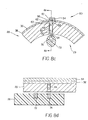
- Drum magnet 72 and a second drum magnet 626 are fixed to slide bar 78 and slide bar 78 is movable between a first position (Figs. 8a and 8b) wherein drum magnet 72 is proximate to inner end 64 and a second position (Figs. 8c and 8d) wherein second drum magnet 76 is positioned proximate to inner end 64.
- Figs. 8a and 8b a first position
- Figs. 8c and 8d second drum magnet 76 is positioned proximate to inner end 64.
- drum magnet 72 confronts inner end 64 with a polarity that repels the second magnetic pole of slide 66 while drum magnet 76 confronts inner end 64 with a magnetic polarity that is attractive to the second magnetic pole of slide 66.
- the polarity of the magnetic field acting against the second magnetic pole of slide 66 can be reversed by physically moving slide bar 78 from the first position to the second position.
- Other movable mechanical structures known to those having ordinary skill in the art can also be used to move slide bar 78 from the first position to the second position.
- a mass of magnetically attractive material such as iron or steel can be used in place of second drum magnet 76 on side bar 78.
- imaging apparatus 20 can comprise electromagnet 80 disposed proximate to imaging drum 28 for generating electromagnetic field that biases slide 66 away from retaining surface 56.
- imaging apparatus 20 can also comprise mechanical actuator 82 such as a solenoid, a motor, or hydraulic, pneumatic or thermal piston or the like, for advancing a third magnet 84 proximate to imaging drum 28 for generating magnetic field to bias slide 66 away from retaining surface 56 to put magnet drum 28 in the "open” state.
- clamp 50 is returned to the "close” state when actuator 82 retracts third magnet 84 to a position distal to clamp 50.
- retaining surface 56 comprises a material that is magnetically attractive to the first magnetic polarity of first end 68 of slide 66.
- This magnetically attractive material can comprise a simple ferro-magnetic magnetic material such as an iron or steel material and can also comprise a retaining surface magnet 67 such as a permanent magnet or an electro-magnet having a magnetic polarity that is opposite to the magnetic polarity of the first end 68 of slide 66 and therefore attractive to slide 66.
- a retaining surface magnet 67 such as a permanent magnet or an electro-magnet having a magnetic polarity that is opposite to the magnetic polarity of the first end 68 of slide 66 and therefore attractive to slide 66.
- the magnetic attraction between slide 66 and retaining surface 56 is defined to provide sufficient clamping force to hold sheet material 36.
- a drum magnet can also be used in this embodiment to provide supplemental bias.
- Fig. 10 can be operated in an "open” and “close” state. This can be accomplished by moving a permanent drum magnet 622 as is shown and described above in connection with the embodiments Figs. 6, 7, 8, or 10. This can also be accomplished using an electro-magnet as is described above.
- slide 66 does not need be a source of a magnetic field.
- slide 66 can comprise any material that can be magnetically attracted by retaining surface 56.
- a mechanical retainer cam can position retainer magnet 67 in a first position associated with the "open” state wherein retainer magnet 67 is proximate to first end 68 of slide 66 to maximize the magnetic attraction between retainer magnet 67 and slide 66.
- retainer cam 77 positions retainer magnet 67 at a position that is distal from first end 68 of slide 66 (Fig. 11b) in order to minimize the magnetic attraction between retainer magnet 67 and slide 66.
- retainer magnet 67 can comprise an electromagnet that is electrically energized to attract slide 66 when clamp 66 is in the "open” state and that is electrically de-energized in the "close” state.
- FIG. 12 shows a perspective view of drum 28 having multiple material clamps.
- retainer 52 comprises a pair of retaining surfaces 56 and 57 supported by a common boss 54.
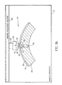
- the location of material clamps 50 on drum 28 are shown in Fig. 13 which depicts a planar schematic view of outer surface 38 of imaging drum 28, in which six material clamps 50 are used for capturing a front edge 86 and a rear edge 88 of thermal imaging media 32.
- imaging drum 28 of the present invention can be arranged so that material clamps 50 can be moved to various positions on the circumference of the drum to accommodate different sizes of media.
- imaging drum 28 can provide multiple predefined sites for the location of magnetic clams or can be adaptable to support the custom location of material clamps 50.
- Fig. 14 shows a partial cross-section view of outer surface 38 of drum 28 having more than one material clamp 50.
- drum 28 comprises a recess 58 and a second recess 90.
- Recesses 58 and 90 have outer ends 60 and 92 respectively at surface 38 defining openings 62 and 94 in outer surface 38.
- Recesses 60 and 90 further comprise inner ends 64 and 94 separated from surface 38.
- Slides 66 and 98 are slidably connected to recesses 58 and 90. Slides 66 and 98 each have a first end 68 and 100 having a first magnetic polarity and a second end 70 and 102 having a second magnetic polarity.
- the magnetic characteristics of slides 66 and 98 can be created by integrating component magnets (not shown) into slides 66 and 98 or by magnetizing slides 66 and 92.
- Drum magnets 72 and 104 are positioned proximate to inner ends 64 and 94 and have a magnetic polarity that is the same as the second magnetic polarity of slides 66 and 92. Thus, drum magnets 72 and 104 repel slides 66 and 92. This biases slides 66 and 92 away from inner ends 64 and 94 toward retaining surfaces 56 and 57. As is shown in Fig. 14, where no sheet material 36 is installed on imaging drum 28, the biasing force is sufficient to propel slides 66 and 92 partially out of recesses 58 and 90 to engage retaining surfaces 56 and 57.
- a first end 86 of sheet material 38 can be inserted for example, between slide 66 and retaining surface 56 while a second end is secured between slide 98 and retaining surface 57.
- Drum magnets 72 and 104 can be operated in an "open” and “close” state using the structures described above for use in conjunction with a drum 28 having a single material clamp 50. It will also be appreciated that clamps 50 of the drum 30 shown in Fig. 12, 13, or 14 can comprise clamps 50 using a drum magnet 72 to repel slide 66 toward retainer and can be also comprise a clamp 50 using a retainer magnet 67 to urge slide 66 toward retaining surface 56.
- slide 66 can include a shaped contact surface that spreads the clamping force of slide 66 across the sheet material 36.
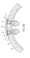
- Figs. 15a and 15b show a single shaped contact surfaces 106 and 108 are connected across multiple material clamps 50.
- drum 28 of this embodiment defines common recesses 110 and 112 in outer surface 38. Each recess contains more than one slide, slide 66a, 66b and 66c. Slides 66a, 66b and 66c are joined to and separated by contact surfaces 106 and 108. Contact surfaces 106 and 108 are then biased in the same manner that slides 66a, 66b, and 66c are biased.
- any of the embodiments of material clamp 50 can be used.
- contact surface of the present invention can be made from a material having a high coefficient of friction.
- contact surfaces 106 and 110 can be made from any number of materials and substances coated, deposited or formed on the surface of any slide or on a separate contact surface. It will be appreciated that the contact surfaces and slides or the present invention can be formed from a common substrate.
Landscapes
- Handling Of Cut Paper (AREA)
- Feeding Of Articles By Means Other Than Belts Or Rollers (AREA)
- Discharging, Photosensitive Material Shape In Electrophotography (AREA)
Abstract
Description
- This invention relates to an imaging apparatus having an imaging drum to movably position sheet material such as thermal imaging material, dye donor sheets and direct writing plates during image formation. More specifically the present invention relates to mechanisms for loading, holding and releasing sheet material on an imaging drum.
- In the art of image generation it is often necessary to form an image on a sheet material such as a thermal media or a plate. Typically the sheet material is secured to an imaging drum and the imaging drum is rotated while a print head forms an image on the material. This can be done by transferring dye or ink to a sheet of material or by modifying the sheet of material. The task of attaching sheet material to the vacuum imaging drum is often rigorous because it requires precise positioning of the sheet material on the imaging drum. Once that sheet material is properly positioned on the drum it is necessary to hold the sheet material in place during imaging operations. Various mechanisms are known in the art to help secure sheet material such as thermal media, dye donor materials and direct write plates to an imaging drum.
- For example, it is known use mechanical clamping mechanisms located at the outer surface of the drum. Such mechanical clamping mechanisms must be robust enough to resist the forces generated by the high speed rotation of the drum. These mechanisms can be hand actuated or they can be automatically actuated as is shown in U.S. Patent No. 5,678,486. Such mechanisms are often complex, and have a clamping force that does not adaptively increase with the speed of drum rotation.
- It is also known to temporarily fix the media and direct write plates onto the outer surface of the drum using magnets. These magnets are attached on top of the media or direct write plates and the force of the magnetic attraction between the magnet and the outer surface holds the media or direct write plates in contact with the drum. It will be appreciated that the magnetic attraction between the magnet and the outer surface must provide sufficient magnetic attraction to resist the centrifugal force of the drum as it rotates. Because the centrifugal force increases with drum rotation speed, it is necessary to use more powerful magnets to secure the media to the drum in order to withstand the centrifugal force created by increased rotational speed. It will be recognized that a point is reached where it becomes impractical to use magnets that have sufficient attractive force to withstand the aforementioned centrifugal force.
- In commonly assigned U.S. patent No. 5,200,708 a dual chamber vacuum imaging drum is used to help controllably position the dye donor media and the thermal media on the surface of an imaging drum. One chamber applies vacuum that holds the lead edge of the dye donor material. Another chamber controls vacuum which holds the trail edge of the thermal print media to the vacuum in imaging drum. With this arrangement, loading a sheet of thermal print media and dye donor material requires that the image processing apparatus feed the lead edge of the thermal print media and dye donor material into position just past the vacuum ports controlled by the respective valve chamber. Then vacuum is applied, gripping the lead edge of the dye donor materials against the vacuum imaging drum surface. Unloading the dye donor material or the thermal print media requires the removal of vacuum from the same chamber so that in edge of the thermal print media or the dye donor material are freed in project out from the surface of the vacuum imaging drum. The image processing apparatus deposits an articulating skive into the path of the free edge of the donor material to lift the edge further and feed the dye donor material to a waist bin or output tray.
- Thus, while the presently known and utilized mechanisms for attaching sheets of material to an imaging drum of an image processing apparatus are commercially viable, a need exists for an imaging drum having an improved mechanism for securing sheet material to a vacuum imaging drum. Further, a need exists for an imaging drum that can secure sheet material even at high rates of drum rotation.
- According to a feature of the present invention, an imaging apparatus is provided for forming images on sheet material. The imaging assembly comprises a print head for forming images on the sheets and an imaging drum having an outer surface. A motor is also provided for rotating the imaging drum. A material clamp is mounted to the imaging drum having a retainer positioning a retaining surface radially outward of the outer surface and forming a space therebetween. A slide is movable within the space between an outer radial position where outward radial movement of the slide is blocked by the retaining surface and an inner radial position distant from the retaining surface. A magnet is provided having a magnetic field biases the slide toward the outer radial position. Rotation of the drum creates centrifugal force that further biases the slide toward the outer radial position.
- According to another embodiment of the present invention, an imaging drum assembly is provided for use in an imaging apparatus for forming images on sheet material. The imaging drum assembly comprises a rotatable imaging drum having an outer surface adapted to attract material to the drum. A material clamp mounted to the drum having a retainer positioning a retaining surface radially outward of the outer surface and forming a space therebetween. A slide is movable within the space between an outer radial position where outward radial movement of the slide is blocked by the retaining surface and an inner radial position distant from the retaining surface. Rotation of the drum creates centrifugal force that biases the slide toward the outer radial position.
- According to a further embodiment of the present invention, an imaging drum assembly is provided for use in an imaging apparatus for forming images on sheet material. The imaging drum assembly comprises a rotatable imaging drum having an outer surface adapted to attract sheet material to the imaging drum. A material clamp is mounted to the drum and has a retainer positioning a retaining surface radially outward of the outer surface and forming a space therebetween. A slide is movable positioned within the space between an outer radial position where outward radial movement of the slide is blocked by the retaining surface and an inner radial position distant from the retaining surface. A biasing member urges the slide toward the outer radial position.
- FIG. 1 is a schematic view of an image processing apparatus of the present invention;
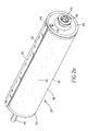
- FIG. 2a is perspective view of the imaging drum of the present invention;
- FIG. 2b is top view of the imaging drum of the present invention;
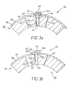
- FIG. 3a shows a partial cross-section view of an embodiment of the present invention.
- FIG. 3b shows a partial cross- section view of an embodiment of the present invention;
- FIG. 4a is a partial cross-section view of an embodiment of the present invention;
- FIG. 4b is a partial cross-section view of an embodiment of the present invention;
- FIG. 4c is a partial cross-section view of an imaging drum of the present invention showing the material clamp wherein sheet material is partially installed in the material clamp;
- FIG. 5a is a partial cross-section view of an embodiment of an imaging drum of the present invention showing the material clamp;
- FIG. 5b is a partial cross-section view of an embodiment of an imaging drum of the present invention showing the magnetic clamp wherein sheet material is installed in the magnetic clamp;
- FIG. 6a is a partial cross-section view of an embodiment of an imaging drum of the present invention having a movable cam positioned to place the material clamp in a close state;
- FIG. 6b is a second partial cross-section view of an embodiment of an imaging drum of the present invention having a movable cam positioned to place the clamp in an open state;
- FIG. 6c shows a partial cross-section view of an embodiment of an imaging drum having an electromagnet.
- FIG. 7a is a partial cross-section view of an embodiment of an imaging drum of the present invention having a movable cam positioned to place the magnetic clamp in a close state;
- FIG. 7b is a partial cross-section view of an embodiment of an imaging drum of the present invention having a movable cam positioned to place the clamp in an open state;
- FIG. 7c is a partial cross-section view of an embodiment of an imaging drum of the present invention having a reversible electromagnet positioned to place the magnetic clamp in a close state;
- FIG. 7d is a partial cross-section view of an embodiment of an imaging drum of the present invention having a reversible electromagnet positioned to place the clamp in an open state;
- FIG. 8a is a partial cross-section view of an embodiment of n imaging drum of the present invention having a movable cam positioned to place the magnetic clamp in a close state;
- FIG. 8b is a second partial cross-section view of an embodiment of an imaging drum of the present invention having a movable cam positioned to place the clamp in a close state;
- FIG. 8c shows an embodiment of the present invention using magnetic attraction between a retaining surface and a slide to provide clamping bias operated in an open state;
- FIG. 8d shows an embodiment of the present invention using magnetic attraction between a retaining surface and a slide to provide clamping bias operated in an open state;
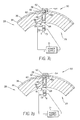
- FIG. 9a shows and embodiment of the present invention having an electromagnet that is external to the drum, biasing the slide to the open position.
- FIG. 9b shows an embodiment of the present invention having a moveable magnet to bias the slide in the open position.
- FIG. 10 shows a partial cross-section view of an imaging drum of the present invention showing an embodiment wherein magnetic attraction is used to bias the slide toward the retaining surface.
- FIG. 11a shows a partial cross-section view of an imaging drum of the present invention wherein magnetic attraction is used to bias the slide toward the retaining surface and operated in a close state.
- FIG. 11b shows a partial cross-section view of an imaging drum of the present invention wherein magnetic attraction is used to bias the slide toward the retaining surface and operated in an open state.
- FIG. 12 shows a perspective view of another drum of the present invention having multiple material clamps.
- FIG. 13 is a schematic planar view of the surface of the drum of the embodiment of FIG. 12, with multiple material clamp locations designated.
- FIG. 14 is a partial cross section view of an embodiment of the vacuum imaging drum of the present invention having plural material clamps.
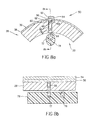
- FIG. 15a is a top view of an imaging drum having multiple material clamps joined by a contact surface.
- FIG. 15b is a cross-section view of an imaging drum having imaging drum having multiple material clamps joined by a contact surface
-
- Referring to Fig. 1, there is illustrated an
image processing apparatus 20 according to the present invention. Theimage processing apparatus 20 is comprised of ahousing 22, sheetmaterial supply assembly 24; aprint head 26; animaging drum 28, amotor 30 and anoutput area 34. Theimage processing apparatus 20 is arranged to form an image onsheet material 36. - The operation of
image processing apparatus 20 comprises transportingsheet material 36 toimaging drum 28, registeringsheet material 36 ondrum 28, wrappingsheet material 36 arounddrum 28, and securingsheet material 36 onimaging drum 28. During printing,motor 30 rotates drum 28 to movesheet material 36past print head 26.Print head 26 forms an image onsheet material 36. After an image has been written onsheet material 36,sheet material 36 is transported tooutput area 34.Sheet material 36 can comprise a thermal transfer media, a dye donor sheet, a direct write plate or other forms of sheet material on which images can be formed. - Figs. 2a and 2b show, respectively a perspective view and a top view of one embodiment of an
imaging drum 28 of the present invention.Imaging drum 28 comprises a cylindrical shaped imaging drumouter surface 38, which can, for example, be manufactured from a length of extruded aluminum tubing. In the embodiment ofimaging drum 28 shown in Figs. 2a and 2b and shown in other embodiments,imaging drum 28 is adapted to use a vacuum to assist in loading, holding, and unloading thesheet material 36. However, it is not necessary to use vacuum to provide such assistance. In this regard,imaging drum 28 can be adapted to use other attractive means such as electrostatic attraction or other attractive forces known in the art to assist during loading, holding and unloading sheet material. Further,imaging drum 28 of the present invention can be used without such assistance simply by holdingsheet material 36 using amaterial clamp 50 to be disclosed hereinafter. - In Figs. 2a and 2b,
imaging drum 28 is shown provided with a plurality ofvacuum grooves 40 onouter surface 38 ofimaging drum 28 and vacuum holes 42 which extend through the vacuum drumouter surface 38. Vacuum holes 42 andvacuum grooves 40 allow a vacuum to be applied through a hollowed-out interior portion (not shown) ofimaging drum 28 for supporting and maintaining the position ofsheet material 36 onimaging drum 28. -
Vacuum imaging drum 28 has two ends closed by avacuum end plate 44, and a drive end plate (not shown). The drive end plate is provided with a centrallydisposed drive spindle 46, which extends outwardly.Vacuum end plate 44 is provided with a centrally disposedvacuum spindle 48, which extends outwardly therefrom. Drivespindle 46 is connected to amotor 30.Motor 30 is fixed tohousing 22 and provides a reversible, variable drive motor for rotatingimaging drum 28.Vacuum spindle 48 is provided with acentral vacuum opening 49.Vacuum opening 49 is connected to a vacuum blower (not shown) which provides thevacuum imaging drum 28 during the loading, scanning and unloading ofsheet media 36. - Figs. 2a and 2b also show a
retainer 52 fixed toimaging drum 28.Retainer 52 includes aboss 54 and a retainingsurface 56.Boss 54 is fixed to drum 28 and extends radially outward ofouter surface 38.Boss 54 holds retainingsurface 56 in a position radially outward ofouter surface 38. - Fig. 3a shows a partial cross section view of
drum 28 andmaterial clamp 50. As is shown in Fig. 3a,imaging drum 28 also comprises arecess 58 inouter surface 38. Retainingsurface 56 is positioned radially outward ofrecesses 58.Recess 58 has anouter end 60 defining anopening 62 inouter surface 38 and aninner end 64 separated fromsurface 38. Aslide 66 is slidable inrecess 58. - A first embodiment of the present invention is shown in Figs. 3a and 3b. Fig 3a shows the
material clamp 50 withsheet material 36 is loaded betweenouter surface 38 and retaining surface 56 (Fig. 3a). In this embodiment, vacuum is applied to hollowed-outinterior portion 29 ofdrum 28 and serves to holdsheet material 36 toouter surface 38. However, asmotor 30 begins to rotatedrum 28, centrifugal force biases slide 66 toward the outer radial position.Slide 66 advances tocontact sheet material 36 and to clampsheet material 36 against retaining surface 56 (Fig. 3b). Thus, in this embodiment, the clamping force exerted byslide 66 and retainingsurface 56 increases as the speed of rotation ofdrum 28 is increased. In this manner, it is possible to rotateimaging drum 28 at a higher speed or to reduce the amount of energy that must be expended by the vacuum during operation. - In other embodiments of the present invention a
material clamp 50 can be used to load, hold and unloadsheet media 36 from theouter surface 38 ofdrum 28 without the need to adaptouter surface 28 to attractsheet media 36. In this embodiment, slide 66 is biased toward the outward radial position. The motion ofslide 66 is stopped at the outer radial position by engagement with retainingsurface 56. Whensheet material 36 is to be mounted to drum 28, a portion ofsheet 36 is disposed betweenslide 66 and retainingsurface 56. The bias acting onslide 66 provides a clamping force to holdsheet material 36 inmaterial clamp 50.Slide 66 can be biased mechanically using spring, pneumatic, thermal or electro-mechanical motors or solenoids. - In the embodiment shown in Fig. 4a, slide 66 has a
first end 68 having a first magnetic polarity and asecond end 70 having a second magnetic polarity. The magnetic polarities ofslide 66 can be created by integrating component magnets (not shown) intoslide 66 or by magnetizingslide 66. As shown in Fig. 4a,first end 68 is associated with a magnetic North pole N whilesecond end 70 is associated with a magnetic South pole S. - A
drum magnet 72 is positioned proximate toinner end 64. In Fig. 3a,drum magnet 72 also has a North magnetic pole N and a South magnetic pole S. However, the South magnetic pole S ofdrum magnet 72 is positioned to confront the South magnetic poles ofslide 66. Thus,drum magnet 72 repelsslide 66. This biases slide 66 away frominner end 64 toward retainingsurface 56. As is shown in Fig. 5a, where nosheet material 36 is installed onimaging drum 28, the magnetic biasing force is sufficient to propelslide 66 partially out ofrecess 58 to engage retainingsurface 56. In the embodiment shown in Fig. 4afirst end 68 ofslide 66 comprises an optional tapered lead-in surface to facilitate loading ofsheet material 36. - It is not critical to the present invention whether a North magnetic pole or a South magnetic pole is used at a particular point in the embodiments of
slide 66,drum magnet 72 or any other magnet discussed hereafter, provided that the magnetic poles ofslide 66,drum magnet 72 or any other magnet discussed hereafter are arranged to produce the biases described. In this regard, the placement of the symbols N and S on any drawing herein are made by way of example and illustration only. - Fig. 4b shows the operation of this embodiment when
sheet material 36 is installed onimaging drum 28. As is shown in Fig. 4b, thesheet material 36 is fixed inmaterial clamp 50 by inserting thesheet material 36 betweenouter surface 38 and retainingsurface 56. This brings thesheet material 36 into contact with thefirst end 68 and causes slide 66 to be displaced intorecess 58. This also causes thesecond end 70 ofslide 66 to come into closer proximity to drummagnet 72. It will be appreciated that the magnetic repulsion between thedrum magnet 72 and slide 66 increases as the separation between thesecond end 70 ofslide 66 anddrum magnet 72 decreases. - As is shown in Fig. 4c, when the
sheet material 36 is fully located inmaterial clamp 50, the magnitude of the of biasing force betweenslide 66 and thedrum magnet 72 reaches a high point. This biasing force is resisted by retainingsurface 56, creating a clamping force to holdsheet material 36 inmaterial clamp 50. Although the forgoing discussion has involved the operation ofmaterial clamp 50 upon insertion of a single sheet ofmaterial 36, the same principles of operation can be used to secure multiple sheets of material toimaging drum 28. - In one embodiment of the present invention, retaining
surface 56 comprises a material that is magnetically attractive to the first magnetic polarity offirst end 68 ofslide 66. This magnetically attractive material can be comprised of a ferro-magnetic material such as an iron or steel material and can be comprised of a magnet having a magnetic polarity that is opposite to the magnetic polarity of thefirst end 68 ofslide 66 and therefore attractive to slide 66. In the embodiment of Figs. 4a - 4c, this provides an additional biasing force to attract theslide 66 toward retainingsurface 56. - In other embodiments of the present invention, drum 28 and
material clamp 50 are arranged to use both centrifugal force and magnetic force to biasslide 66. One example of such an embodiment is shown in Figs 5a and 5b. As is shown in Fig. 5a, slide 66 is arranged for movement in a manner that is consistent with the centrifugal force generated by rotation ofdrum 28.Slide 66 also generates a magnetic field. This magnetic field is repelled by the magnetic field ofdrum magnet 72 to provide a magnetic force to biasslide 66 in the manner that is described above. - Thus this embodiment of the present invention provides the advantage of having two principal clamping forces. The first clamping force is the material clamping force that operates as described above. The second clamping force comes into being when
motor 30 turns drum 28 and is generated by centrifugal force acting againstslide 66.Slide 66 is free to move toward and away from the center ofdrum 28. Thus, as is shown in Fig. 5b, asdrum 28 rotates, slide 66 is propelled toward retainingsurface 56 by centrifugal force. Further, the rate of drum rotation increases, the centrifugal force increases concomitantly and, the clamping force exerted byslide 66 and retainingsurface 56 againstsheet material 38 also increases. Thus, in this embodiment,material clamp 50 automatically increases the clamping force acting on thesheet material 36 with increases in the speed of rotation ofdrum 28. - It may be beneficial to provide
magnetic drum 28 with amaterial clamp 50 structure that will allowmaterial clamp 50 to be operated in a "close" state to hold sheet material inmaterial clamp 50 and in an "open" state to facilitate insertion and removal ofsheet material 38 inmaterial clamp 50. - In this regard, one embodiment of
drum 38 of the present invention has amaterial clamp 50 that is transitioned from an "open" state to a "close" state by varying the intensity of the magnetic field that acts againstmagnetic slide 66 between a high level associated with the "close" state and a low level that is associated with the "open" state. In the "close" state, the intensity of the magnetic field that acts against the second pole ofslide 66 is sufficient to fully biasslide 66 and to causematerial clamp 50 to operate as described above. In contrast, in the "open" state, the intensity of the magnetic field that acts against the second pole ofslide 66 is substantially attenuated or eliminated. This, in turn, substantially attenuates or eliminates the biasforce urging slide 66 toward retainingsurface 56, permitting the user to positionsheet material 36 intomaterial clamp 50 with little or no resistance. After thesheet material 36, is positioned intomaterial clamp 50,material clamp 50 is returned to the "close" state to lock in the position of thesheet material 50 on the drum. - Figs. 6a and 6b, show an embodiment of a
drum 28 of the present invention having aclamp 50 with a mechanical structure for attenuating the magnetic bias exerted bydrum magnet 72 againstslide 66 in order to transitionclamp 50 from the "open" state to the "close" state. In this embodiment, slide 66 is selectively repelled and attracted mechanically by varying the polarity of the magnetic field that acts against the second magnetic pole ofslide 66. This is accomplished by physically moving thedrum magnet 72 from a first position proximate toinner end 64 to a second position that is separate from theinner end 64. In this embodiment,drum magnet 72 is positioned in the first position whenmaterial clamp 24 is in the "open" state, and drummagnet 72 is moved to the second position whenmaterial clamp 24 is in the "close" state. - As shown in Fig. 6a,
drum magnet 72 has a first magnetic pole that repelsslide 66 atfirst end 73 and a second magnetic pole atsecond end 75.Drum magnet 72 is fixed torotatable cam 74. When it is desired to placematerial clamp 50 in the "close" state,cam 74 positions first end 73 ofdrum magnet 72 proximate toinner end 64. This biases slide 66 away fromfirst end 66 and toward retainingsurface 56. When it is desired to placematerial clamp 50 in the "open" state,cam 74 is rotated to a position, shown in Fig. 6b, whereinfirst end 73 ofdrum magnet 72 is separated frominner end 64. It will be appreciated that other movable mechanical structures known to those having ordinary skill in the art can also be used to movedrum magnet 72 from the first position to the second position. - In an alternative embodiment of the present invention shown in Fig. 6c, an electrical structure is used to attenuate the magnetic bias exerted by
drum magnet 72 againstslide 66 in order to transitionclamp 50 from the "open" state to the "close" state. In this embodiment,drum magnet 72 comprises an electromagnet andimaging apparatus 10 further comprises anelectromagnet power supply 71.Electromagnet power supply 71 is electrically connected to the electromagnet and supplies a reversible flow of current to the electromagnet. In this embodiment, the intensity of the magnetic field to which slide 66 is exposed is defined by the intensity of current flow through the electromagnet. Accordingly, when it is desired to placematerial clamp 50 in the "open" state, the flow of electric current through the electromagnet is stopped or substantially reduced. This eliminates or substantially reduces the magneticbias urging slide 66 away toward retainingsurface 56. When it is desired to placematerial clamp 50 in the "close" mode, the electromagnetic power supply causes current to flow in through the electromagnet. This causesdrum magnet 72 to generate a magnetic field which, in turn, biases slide 66 toward retainingsurface 56. -
Material clamp 50 can also be transitioned from an "open" state to a "close" state by varying the he polarity of the magnetic field that acts againstmagnetic slide 66 between a repellant polarity that is associated with the "close state" and an attractive polarity that is associated with the "open" state. - Figs. 7a and 7b show an embodiment of an
imaging drum 28 of the present invention having a mechanical structure for reversing the polarity of the magnetic field that acts againstslide 66 in order to transitionclamp 50 from a "close' state to an "open" state. In this embodiment,drum magnet 72 is a bi-polar magnet having opposite magnetic polarities at different points ondrum magnet 72. By physically moving thedrum magnet 72 from a first position Fig. 7a wherein a repellant pole is proximate toinner end 64 to a second position Fig. 7b wherein an attractive magnetic pole is proximate toinner end 64,drum magnet 72 can be transitioned from the "close" state to the "open" state. - In this embodiment,
drum magnet 72 has a magnetic pole that repelsslide 66 atfirst end 73 and a second magnetic pole atsecond end 75 that attractsslide 66.Drum magnet 72 is fixed torotatable cam 74.Rotatable cam 74 is rotatable between a first position, shown in Fig. 5a is in a position that is proximate toinner end 64 and a second position, shown in Fig. 7b, whereinsecond end 75 is positioned proximate toinner end 64. It will be appreciated that other movable mechanical structures known to those having ordinary skill in the art can also be used to movedrum magnet 72 from the first position to the second position. - Figs. 7c and 7d show an alternative embodiment of the present invention wherein
drum magnet 72 comprises an electromagnet connected to a reversible source of electricity as is seen in Figs. 7a and 7b. The polarity of the electromagnet can be reversed by reversing the flow of current through the electromagnet. - Another embodiment of
drum 28 of the present invention, shown in Fig. 8a - 8d, uses a different mechanical structure for reversing the polarity of the magnetic field that acts againstslide 66 in order to transitionclamp 50 from a "close' state to an "open" state. As is shown in Fig. 8a, in this embodiment aslide bar 78 is also fixed to drum 28.Drum magnet 72 and a second drum magnet 626 are fixed to slidebar 78 andslide bar 78 is movable between a first position (Figs. 8a and 8b) whereindrum magnet 72 is proximate toinner end 64 and a second position (Figs. 8c and 8d) whereinsecond drum magnet 76 is positioned proximate toinner end 64. In the embodiment of Figs. 8a - 8d,drum magnet 72 confrontsinner end 64 with a polarity that repels the second magnetic pole ofslide 66 whiledrum magnet 76 confrontsinner end 64 with a magnetic polarity that is attractive to the second magnetic pole ofslide 66. Accordingly, in this embodiment, the polarity of the magnetic field acting against the second magnetic pole ofslide 66 can be reversed by physically movingslide bar 78 from the first position to the second position. Other movable mechanical structures known to those having ordinary skill in the art can also be used to moveslide bar 78 from the first position to the second position. It will also be appreciated that, a mass of magnetically attractive material such as iron or steel can be used in place ofsecond drum magnet 76 onside bar 78. - Structures outside of
imaging drum 28 can also be used to transition amaterial clamp 50 between an "open" state and a "close" state. As is shown in Fig. 9a,imaging apparatus 20 can compriseelectromagnet 80 disposed proximate toimaging drum 28 for generating electromagnetic field that biases slide 66 away from retainingsurface 56. As is shown in Fig. 9b,imaging apparatus 20 can also comprisemechanical actuator 82 such as a solenoid, a motor, or hydraulic, pneumatic or thermal piston or the like, for advancing athird magnet 84 proximate toimaging drum 28 for generating magnetic field tobias slide 66 away from retainingsurface 56 to putmagnet drum 28 in the "open" state. In this embodiment, clamp 50 is returned to the "close" state when actuator 82 retractsthird magnet 84 to a position distal to clamp 50. - However, as is shown in Figs 10a, 10b and 10c, the present invention can be practiced using magnetic attraction between retaining
surface 56 andfirst end 68 ofslide 66 to provide primary clamping force for the material clamp. In this embodiment, retainingsurface 56 comprises a material that is magnetically attractive to the first magnetic polarity offirst end 68 ofslide 66. This magnetically attractive material can comprise a simple ferro-magnetic magnetic material such as an iron or steel material and can also comprise a retainingsurface magnet 67 such as a permanent magnet or an electro-magnet having a magnetic polarity that is opposite to the magnetic polarity of thefirst end 68 ofslide 66 and therefore attractive to slide 66. As is shown in Figs. 10a, 10b and 10c, the magnetic attraction betweenslide 66 and retainingsurface 56 is defined to provide sufficient clamping force to holdsheet material 36. In this embodiment it is not necessary to use a drum magnet. However, a drum magnet can also be used in this embodiment to provide supplemental bias. - The embodiment of Fig. 10 can be operated in an "open" and "close" state. This can be accomplished by moving a permanent drum magnet 622 as is shown and described above in connection with the embodiments Figs. 6, 7, 8, or 10. This can also be accomplished using an electro-magnet as is described above.
- In the embodiment of the present invention using magnetic attraction between
slide 66 and retainingsurface 56 as the principalforce biasing slide 66 toward retainingsurface 56, slide 66 does not need be a source of a magnetic field. Instead, in thisembodiment slide 66 can comprise any material that can be magnetically attracted by retainingsurface 56. - Where slide 66 does not generate a magnetic field it is possible to transition
clamp 50 from an open state to a close state by reducing the intensity of the magneticfield attracting slide 66 toward retainingsurface 56. As is shown in Fig. 11a, a mechanical retainer cam can positionretainer magnet 67 in a first position associated with the "open" state whereinretainer magnet 67 is proximate tofirst end 68 ofslide 66 to maximize the magnetic attraction betweenretainer magnet 67 andslide 66. In the "close"state retainer cam 77positions retainer magnet 67 at a position that is distal fromfirst end 68 of slide 66 (Fig. 11b) in order to minimize the magnetic attraction betweenretainer magnet 67 andslide 66. Similarly,retainer magnet 67 can comprise an electromagnet that is electrically energized to attractslide 66 whenclamp 66 is in the "open" state and that is electrically de-energized in the "close" state. - As is shown in Figs. 12, 13, and 14, more than one
material clamp 50 can be used in conjunction withvacuum imaging drum 28. Fig. 12 shows a perspective view ofdrum 28 having multiple material clamps. As is shown in this embodiment,retainer 52 comprises a pair of retainingsurfaces common boss 54. The location of material clamps 50 ondrum 28 are shown in Fig. 13 which depicts a planar schematic view ofouter surface 38 ofimaging drum 28, in which six material clamps 50 are used for capturing afront edge 86 and arear edge 88 of thermal imaging media 32. - While the material clamps 50 of the present invention are shown in fixed locations on
imaging drum 28, it will be appreciated thatimaging drum 28 of the present invention can be arranged so that material clamps 50 can be moved to various positions on the circumference of the drum to accommodate different sizes of media. In this regard,imaging drum 28 can provide multiple predefined sites for the location of magnetic clams or can be adaptable to support the custom location of material clamps 50. - Fig. 14 shows a partial cross-section view of
outer surface 38 ofdrum 28 having more than onematerial clamp 50. As is shown in Fig. 14,drum 28 comprises arecess 58 and asecond recess 90.Recesses outer ends 60 and 92 respectively atsurface 38 definingopenings outer surface 38.Recesses inner ends surface 38.Slides recesses Slides first end second end slides slides slides 66 and 92. -
Drum magnets inner ends slides 66 and 92. Thus, drummagnets slides 66 and 92. This biases slides 66 and 92 away frominner ends surfaces sheet material 36 is installed onimaging drum 28, the biasing force is sufficient to propelslides 66 and 92 partially out ofrecesses surfaces first end 86 ofsheet material 38 can be inserted for example, betweenslide 66 and retainingsurface 56 while a second end is secured betweenslide 98 and retainingsurface 57. -
Drum magnets drum 28 having asingle material clamp 50. It will also be appreciated that clamps 50 of thedrum 30 shown in Fig. 12, 13, or 14 can comprise clamps 50 using adrum magnet 72 to repelslide 66 toward retainer and can be also comprise aclamp 50 using aretainer magnet 67 to urgeslide 66 toward retainingsurface 56. - With respect to any embodiment herein, various surfaces can be used to capture and hold the sheet media in
material clamp 50. For example, slide 66 can include a shaped contact surface that spreads the clamping force ofslide 66 across thesheet material 36. In this regard, for example, Figs. 15a and 15b show a single shaped contact surfaces 106 and 108 are connected across multiple material clamps 50. As is shown in Fig. 15a, drum 28 of this embodiment definescommon recesses outer surface 38. Each recess contains more than one slide, slide 66a, 66b and 66c. Slides 66a, 66b and 66c are joined to and separated bycontact surfaces material clamp 50 can be used. - Any contact surface of the present invention can be made from a material having a high coefficient of friction. In this regard, contact surfaces 106 and 110 can be made from any number of materials and substances coated, deposited or formed on the surface of any slide or on a separate contact surface. It will be appreciated that the contact surfaces and slides or the present invention can be formed from a common substrate.
Claims (10)
- An imaging drum (28) assembly for use in an apparatus for forming images on sheet material (36), comprising:wherein rotation of the drum (28) creates centrifugal force that further biases the slide toward the outer radial position.a rotatable imaging drum (28) having an outer surface;a material clamp (50) mounted to the drum havinga retainer (52) positioning a retaining surface (56) radially outward of the outer surface and forming a space therebetween;a slide (66) movable within the space between an outer radial position where outward radial movement of the slide (66) is blocked by the retaining surface and an inner radial position distant from the retaining surface; and,a magnet having a magnetic field biasing the slide toward the outer radial position;
- The imaging drum assembly of claim 1 wherein the magnetic bias between the magnet and the slide is adjustable between a high level and a lower level.
- The imaging drum assembly of claim 2 wherein the magnet is an electromagnet.
- The imaging drum assembly of claim 2 wherein the magnet is movably positioned between a position proximate to the slide and a position that is distant to the slide.
- The imaging drum assembly of claim 1 wherein the slide has a magnetic field.
- The imaging drum assembly of claim 5, further comprising a second magnet having a magnetic field that biases the slide away from the outer radial position and a magnet support to hold the magnet and second magnet
wherein the magnet support is moveable between a first location positioning the magnet proximate to the slide and a second location positioning the second drum magnet proximate to the slide. - An imaging apparatus, for use in an apparatus for forming images on sheet material, the imaging drum assembly comprising:an imaging drum having an outer surface and a recess with the recess having an outer end defining an opening in outer surface and an inner end separated from the opening;a boss fixed to the drum and defining a retainer above the recess in the outer surface;a slide connected to the recess and moveable between a first position proximate to the retainer and a second position distant from the retainer and comprising a slide having a magnet with a first magnetic field;a drum magnet having a repellant magnetic field that biases the slide magnet away from the drum magnet; and,a magnet support positioning the drum magnet proximate to the inner end of the recess.
- The imaging apparatus of claim 7, wherein the drum magnet comprises a bi-polar magnet having at a first end an attractive magnetic field that biases the slide magnet toward the bi-polar drum magnet and a second end a repellant magnetic field that biases the slide magnet away from the bi-polar drum magnet and wherein the magnet support movably locates the bi-polar drum magnet between a first location wherein the first end of the bi-polar magnet is proximate to the inner end of the recess and a second location wherein the second end of the bi-polar magnet proximate to the inner end of the recess.
- An imaging drum assembly for use in an imaging apparatus for forming images on sheet material; the imaging drum assembly comprising:a rotatable imaging drum having an outer surface adapted to attract sheet material to the drum;a material clamp mounted to the imaging drum having a retainer positioning a retaining surface radially outward of the outer surface and forming a space therebetween and a slide movable within the space between an outer radial position where outward radial movement of the slide is blocked by the retaining surface and an inner radial position distant from the retaining surface; and;a biasing member urging the slide toward the outer radial position.
- The imaging drum assembly of claim 9 wherein the magnetic bias between the magnet and the slide is adjustable between a high level and a lower level.
Applications Claiming Priority (2)
| Application Number | Priority Date | Filing Date | Title |
|---|---|---|---|
| US845145 | 2001-04-30 | ||
| US09/845,145 US6729235B2 (en) | 2001-04-30 | 2001-04-30 | Imaging apparatus and imaging drum having material clamp |
Publications (2)
| Publication Number | Publication Date |
|---|---|
| EP1254779A2 true EP1254779A2 (en) | 2002-11-06 |
| EP1254779A3 EP1254779A3 (en) | 2003-08-13 |
Family
ID=25294521
Family Applications (1)
| Application Number | Title | Priority Date | Filing Date |
|---|---|---|---|
| EP02076534A Withdrawn EP1254779A3 (en) | 2001-04-30 | 2002-04-18 | Imaging apparatus and imaging drum having material clamp |
Country Status (3)
| Country | Link |
|---|---|
| US (1) | US6729235B2 (en) |
| EP (1) | EP1254779A3 (en) |
| JP (1) | JP2002338079A (en) |
Cited By (2)
| Publication number | Priority date | Publication date | Assignee | Title |
|---|---|---|---|---|
| CN103019073A (en) * | 2011-09-21 | 2013-04-03 | 富士施乐株式会社 | Image forming apparatus |
| EP4530036A1 (en) * | 2023-09-29 | 2025-04-02 | Kocher+Beck GmbH + Co. Rotationsstanztechnik KG | Rotary die cutter |
Families Citing this family (11)
| Publication number | Priority date | Publication date | Assignee | Title |
|---|---|---|---|---|
| CA2397400A1 (en) * | 2002-06-26 | 2003-12-26 | Seppo Ilmari Leppanen | Method and apparatus for clamping a printing media |
| US6722280B2 (en) * | 2002-08-09 | 2004-04-20 | Agfa Corporation | Method and system for simultaneous loading and unloading of substrates in platestter |
| US20050120898A1 (en) * | 2003-12-05 | 2005-06-09 | Presstek, Inc. | Magnetic plate retention |
| CN101327593A (en) * | 2007-06-20 | 2008-12-24 | 鸿富锦精密工业(深圳)有限公司 | Magnetic holder |
| JP4925471B2 (en) * | 2008-08-11 | 2012-04-25 | 雅幸 井爪 | Plate mounting apparatus for printing press and printing press |
| JP5482372B2 (en) * | 2010-03-29 | 2014-05-07 | 富士ゼロックス株式会社 | Image forming apparatus |
| JP5691674B2 (en) * | 2011-03-09 | 2015-04-01 | 富士ゼロックス株式会社 | Image forming apparatus and transfer apparatus |
| JP5862158B2 (en) * | 2011-09-26 | 2016-02-16 | 富士ゼロックス株式会社 | Image forming apparatus |
| JP2013174655A (en) * | 2012-02-23 | 2013-09-05 | Fuji Xerox Co Ltd | Image forming apparatus |
| US9321257B2 (en) | 2013-04-04 | 2016-04-26 | Nike, Inc. | Cylinder with recessed portions for holding tubular articles for printing |
| US9409414B2 (en) | 2013-04-04 | 2016-08-09 | Nike, Inc. | Vacuum cylinder with recessed portions for holding articles for printing |
Citations (2)
| Publication number | Priority date | Publication date | Assignee | Title |
|---|---|---|---|---|
| US5200708A (en) | 1991-09-11 | 1993-04-06 | Thomson Consumer Electronics, Inc. | Apparatus for the virtual expansion of power supply capacity |
| US5678486A (en) | 1994-09-20 | 1997-10-21 | Man Roland Druckmaschinen Ag | Gripper cylinder |
Family Cites Families (30)
| Publication number | Priority date | Publication date | Assignee | Title |
|---|---|---|---|---|
| US2145520A (en) | 1937-03-11 | 1939-01-31 | Martin Machinery Corp | Gathering machine |
| US2231291A (en) | 1939-09-02 | 1941-02-11 | Ditto Inc | Duplicating machine and block-out means therefor |
| US2999453A (en) | 1949-05-18 | 1961-09-12 | Ditto Inc | Means for line printing |
| US2730949A (en) | 1954-07-30 | 1956-01-17 | Addressograph Multigraph | Clamp for master sheets of printing machine |
| US3191530A (en) | 1963-11-18 | 1965-06-29 | Cutler Hammer Inc | Detector system for plural unit printing press |
| US3438324A (en) | 1967-01-18 | 1969-04-15 | Paper Converting Machine Co | Magnetic printing plate holddown means |
| US3595567A (en) | 1969-01-17 | 1971-07-27 | Harris Intertype Corp | Sheet detection control for sheet-handling apparatus,particulary a printing press |
| DE2621250C2 (en) | 1976-05-13 | 1982-07-22 | Heidelberger Druckmaschinen Ag, 6900 Heidelberg | Sheet query device in a rotary printing press |
| US4250810A (en) * | 1979-09-25 | 1981-02-17 | International Business Machines Corporation | Centrifugal clamp on a high speed print drum |
| JPS5996984A (en) | 1982-11-26 | 1984-06-04 | Riso Kagaku Corp | Stencil paper retaining device for printer |
| US4528906A (en) | 1983-07-29 | 1985-07-16 | Riso Kagaku Corporation | System for retaining stencil printing master on printing drum |
| JPS61104854A (en) | 1984-10-29 | 1986-05-23 | Riso Kagaku Corp | Stencil paper retaining device for printer |
| JPS62140952A (en) * | 1985-12-17 | 1987-06-24 | Matsushita Graphic Commun Syst Inc | Device for holding end of sheet wound on outer face of drum |
| JPH01278381A (en) | 1988-05-02 | 1989-11-08 | Mitsubishi Electric Corp | Recording paper clamping device in printer |
| US4903957A (en) | 1988-11-02 | 1990-02-27 | Polaroid Corporation | Dynamically stable sheet clamping system for high speed sheet handling drums |
| JPH03279151A (en) * | 1990-03-23 | 1991-12-10 | Nippon Sekisoo Kogyo Kk | Sheet product piling device |
| ATE130252T1 (en) * | 1990-12-21 | 1995-12-15 | Heidelberger Druckmasch Ag | QUICK CLAMP DEVICE. |
| US5268708A (en) | 1991-08-23 | 1993-12-07 | Eastman Kodak Company | Laser thermal printer with an automatic material supply |
| US5218379A (en) | 1991-09-26 | 1993-06-08 | Eastman Kodak Company | Photographic material clamp |
| DE4200406C2 (en) | 1992-01-10 | 1996-10-10 | Heidelberger Druckmasch Ag | Gripper device on sheet-fed rotary printing machines |
| US5291260A (en) * | 1992-12-03 | 1994-03-01 | Eastman Kodak Company | Image forming apparatus having a transfer drum with a vacuum sheet holding mechanism |
| US5518231A (en) * | 1993-04-19 | 1996-05-21 | Xerox Corporation | Self adjusting sheet gripping apparatus |
| DE4326261C2 (en) * | 1993-08-05 | 2002-03-21 | Heidelberger Druckmasch Ag | Gripper device for rotary printing machines |
| DE4338664C2 (en) | 1993-11-12 | 1995-09-14 | Roland Man Druckmasch | Method and device for controlling an automated printing plate changing process in printing machines |
| DE9411121U1 (en) * | 1994-07-09 | 1994-09-01 | Man Roland Druckmaschinen Ag, 63069 Offenbach | Gripper cylinder in a folder |
| JP3279151B2 (en) | 1995-10-23 | 2002-04-30 | トヨタ自動車株式会社 | Semiconductor device and manufacturing method thereof |
| US6014162A (en) | 1997-08-18 | 2000-01-11 | Eastman Kodak Company | Vacuum imaging drum with media contours |
| DE19854845B4 (en) | 1998-01-30 | 2011-02-24 | Heidelberger Druckmaschinen Ag | Method and device for automatic detection of at least one printing plate edge |
| AU6227998A (en) | 1998-02-23 | 1999-09-06 | Indigo N.V. | Sheet grippers |
| US6454255B1 (en) * | 2000-12-19 | 2002-09-24 | Pitney Bowes Inc. | Recirculating gripper accumulator having a circular paper path |
-
2001
- 2001-04-30 US US09/845,145 patent/US6729235B2/en not_active Expired - Fee Related
-
2002
- 2002-04-18 EP EP02076534A patent/EP1254779A3/en not_active Withdrawn
- 2002-04-30 JP JP2002127888A patent/JP2002338079A/en active Pending
Patent Citations (2)
| Publication number | Priority date | Publication date | Assignee | Title |
|---|---|---|---|---|
| US5200708A (en) | 1991-09-11 | 1993-04-06 | Thomson Consumer Electronics, Inc. | Apparatus for the virtual expansion of power supply capacity |
| US5678486A (en) | 1994-09-20 | 1997-10-21 | Man Roland Druckmaschinen Ag | Gripper cylinder |
Cited By (3)
| Publication number | Priority date | Publication date | Assignee | Title |
|---|---|---|---|---|
| CN103019073A (en) * | 2011-09-21 | 2013-04-03 | 富士施乐株式会社 | Image forming apparatus |
| CN103019073B (en) * | 2011-09-21 | 2016-09-21 | 富士施乐株式会社 | Image processing system |
| EP4530036A1 (en) * | 2023-09-29 | 2025-04-02 | Kocher+Beck GmbH + Co. Rotationsstanztechnik KG | Rotary die cutter |
Also Published As
| Publication number | Publication date |
|---|---|
| EP1254779A3 (en) | 2003-08-13 |
| US6729235B2 (en) | 2004-05-04 |
| US20020191995A1 (en) | 2002-12-19 |
| JP2002338079A (en) | 2002-11-27 |
Similar Documents
| Publication | Publication Date | Title |
|---|---|---|
| EP1254779A2 (en) | Imaging apparatus and imaging drum having material clamp | |
| US6626476B1 (en) | Robotic gripper apparatus | |
| CN101351769B (en) | Contactless shutter actuation systems and methods | |
| JP3970359B2 (en) | Device for gripping and holding a flat substrate | |
| US5363261A (en) | Disk drive actuator latch | |
| JP5335826B2 (en) | Shutter drive system | |
| US20090072636A1 (en) | Adjustable mid air gap magnetic latching solenoid | |
| KR960007178A (en) | Screen printing device | |
| US5678486A (en) | Gripper cylinder | |
| TW200844639A (en) | Light amount adjustment apparatus and image pickup apparatus | |
| JP2003173603A (en) | Disk drive tray lock device | |
| EP0982147A3 (en) | A magnetic arrangement for printhead positioning in an image processing apparatus | |
| EP0236439B1 (en) | Single station printer | |
| WO1999042290A1 (en) | Sheet grippers | |
| JP6683516B2 (en) | Focal plane shutter and imaging device | |
| CN219320623U (en) | Driving device for camera module and electronic equipment | |
| JP4574800B2 (en) | Electromagnetic actuator and camera shutter device | |
| JPH0726810Y2 (en) | Actuator | |
| CN111465752A (en) | Actuator control system for a bi-stable electric rocker latch | |
| JP2005016640A (en) | Solenoid valve | |
| JPS6254691A (en) | Method of controlling robot hand | |
| JP4080938B2 (en) | Paper transport device | |
| JP2002103164A (en) | Workpiece picking device | |
| CN107499934A (en) | The magnet holding device of the lamellar magnet of sticking and the conveying device including the device | |
| CA3227408A1 (en) | Switchable magnetic apparatus with reduced switching force and methods thereof |
Legal Events
| Date | Code | Title | Description |
|---|---|---|---|
| PUAI | Public reference made under article 153(3) epc to a published international application that has entered the european phase |
Free format text: ORIGINAL CODE: 0009012 |
|
| AK | Designated contracting states |
Kind code of ref document: A2 Designated state(s): AT BE CH CY DE DK ES FI FR GB GR IE IT LI LU MC NL PT SE TR |
|
| AX | Request for extension of the european patent |
Free format text: AL;LT;LV;MK;RO;SI |
|
| PUAL | Search report despatched |
Free format text: ORIGINAL CODE: 0009013 |
|
| AK | Designated contracting states |
Designated state(s): AT BE CH CY DE DK ES FI FR GB GR IE IT LI LU MC NL PT SE TR |
|
| AX | Request for extension of the european patent |
Extension state: AL LT LV MK RO SI |
|
| RIC1 | Information provided on ipc code assigned before grant |
Ipc: 7B 41F 21/10 B Ipc: 7B 41J 13/22 A |
|
| STAA | Information on the status of an ep patent application or granted ep patent |
Free format text: STATUS: THE APPLICATION HAS BEEN WITHDRAWN |
|
| 17P | Request for examination filed |
Effective date: 20040204 |
|
| 18W | Application withdrawn |
Effective date: 20040308 |