EP1254458B1 - Container for optical disks, tray and magazine type player therefor - Google Patents
Container for optical disks, tray and magazine type player therefor Download PDFInfo
- Publication number
- EP1254458B1 EP1254458B1 EP01903721A EP01903721A EP1254458B1 EP 1254458 B1 EP1254458 B1 EP 1254458B1 EP 01903721 A EP01903721 A EP 01903721A EP 01903721 A EP01903721 A EP 01903721A EP 1254458 B1 EP1254458 B1 EP 1254458B1
- Authority
- EP
- European Patent Office
- Prior art keywords
- tray
- container
- disk
- trays
- support area
- Prior art date
- Legal status (The legal status is an assumption and is not a legal conclusion. Google has not performed a legal analysis and makes no representation as to the accuracy of the status listed.)
- Expired - Lifetime
Links
- 230000003287 optical effect Effects 0.000 title claims description 51
- 238000003780 insertion Methods 0.000 claims description 6
- 230000037431 insertion Effects 0.000 claims description 6
- 239000010437 gem Substances 0.000 claims description 4
- 229910001751 gemstone Inorganic materials 0.000 claims description 4
- 230000000630 rising effect Effects 0.000 claims description 4
- 210000001331 nose Anatomy 0.000 description 14
- 230000008901 benefit Effects 0.000 description 12
- 230000007246 mechanism Effects 0.000 description 7
- 238000004806 packaging method and process Methods 0.000 description 3
- 239000000428 dust Substances 0.000 description 2
- 239000000463 material Substances 0.000 description 2
- 238000000034 method Methods 0.000 description 2
- 230000008569 process Effects 0.000 description 2
- 230000004888 barrier function Effects 0.000 description 1
- 230000008859 change Effects 0.000 description 1
- 238000010276 construction Methods 0.000 description 1
- 230000001419 dependent effect Effects 0.000 description 1
- 230000000694 effects Effects 0.000 description 1
- 230000003993 interaction Effects 0.000 description 1
- 239000002245 particle Substances 0.000 description 1
- 239000002699 waste material Substances 0.000 description 1
- 230000003245 working effect Effects 0.000 description 1
Images






Definitions
- the invention refers to a container for optical disks, a tray for such container and a magazine type player adapted to be used with such container.
- Containers for optical disks are known e.g. from US-A-5,936,935, EP-A-0 833 332, US-A-5,975,291, DE-A-197 58 211 or US-A-5,366,073.
- all of these known containers either have sum of bottom plate thickness and cover plate thickness larger than thickness of a single tray or, in case of a tray being largely removeable from the container, the tray thickness is larger than the sum of bottom and cover plate thicknesses.
- Object of the invention is to provide a container for optical disks in which many disks may be stored within a comparatively small space.
- a container for optical disks according to the invention is defined by the features of claim 1.
- the outer dimensions of the container according to the invention substantially equal those of a standard Jewel box or a standard DVD storage box.
- the container height is thus about 10mm, its depth is about 125mm and its width is about 142mm.
- Each tray has a height of about 2.5mm while the sum of thicknesses of bottom and cover plate is also about 2.5mm. This has the advantage, that it fits to existing storage means, and that no compatibility problems occur.
- a Container according to the invention is open at one side for insertion and removal of a tray and it is partially closed at the opposite side. This has the advantage that the mechanical stability of the container is increased in comparison to a container having two opposing open sides.
- the partial opening is advantageously used to push out a tray, either manually or automatically, to check content of filling state of the tray etc.
- the container according to the invention comprises releasable locking means for locking the trays in their position within the container. Transportation or other handling of the container is thus possible without the risk of unintentional opening and of loosing a disk.
- the container comprises at least one orientation groove. This enables correct orientation in relation to a playback device and prevents unintentional wrong insertion.
- the orientation groove is arranged near an edge of the container. This makes possible to access to a part of the tray via the orientation groove, e.g. for pushing or pulling out the tray or for checking whether a tray is inserted or not.
- the container is provided with an identification area. This enables quick identification of the container and its content.
- the container according to the invention preferably comprises a read-write protection means. This enables the user to select, in case of writable disks, which disk should be write protected.
- the container according to the invention is, in top view, of rectangular shape, having first and second base lines.
- the first base line is shorter than the second base line and the first base line is less than 5% larger than the diameter of the largest optical disk to be stored within the container.
- the second base line is less than 20% larger than the diameter of the largest optical disk to be stored within the container.
- the container is provided with side walls being arranged at the outer ends of the second base line and extending in direction of the first base line.
- the container further is provided with openings being arranged between the side walls and extending along the second base line, said openings being closed by side surfaces of trays which are accommodated within the container, said side surfaces of said trays, and surfaces of side walls and end surfaces of bottom plate and cover plate forming a substantially even plane.
- the container according to the invention is provided with a first locking means which is arranged to lock and unlock all of the trays stored within the container, and with second locking means for locking and releasing each single tray independently of the other trays.
- first locking means which is arranged to lock and unlock all of the trays stored within the container
- second locking means for locking and releasing each single tray independently of the other trays.
- a tray for a container for optical disks has a thickness of substantially the sum of container cover plate and bottom plate thicknesses and comprises gripping holes, support areas for supporting an optical disk at the lower surface of its outer rim, an opening in said support area for enabling access up to the radially outwardly area of an optical disk, the upper surface of said support area rising in cross sectional view from its radially inner end to its radially outer end, guiding means for guiding the tray within the container and an orientation hole.
- the guiding means are arranged in asymmetric way in order to form a fail-safe means for the orientation of the tray when being input into the container.
- the guiding means are, according to a preferred solution, projections, which cooperate with guide rails of the side walls of the container.
- the orientation or centering hole is similar to the one provided by the DVD-RAM standard or another standard for correct orientation of the tray within a scanning device.
- a tray for a container for optical disks comprises a support area for supporting an optical disk at the lower surface of its outer rim and a releasable disk holder for holding an optical disk at the upper surface of its outer rim.
- the support area may of course also support the disk at its upper surface while its lower surface is held by the disk holder.
- a single holder is sufficient to hold the disk sufficiently.
- at least two disk holders are preferred as these might be made smaller and of less stable or strong material, thus being cheaper to produce.
- a preferred solution is to provide four disk holders arranged in the area of the four edges of a rectangularly shaped tray in order to keep stability of tray and disk holder as large as possible.
- An adapter for a tray of a disk storage container comprises an outer shape to fit in said tray, gripping holes and an inner support area for supporting an optical disk at the lower surface of its outer rim, an outer support area for being supported by a support area of said tray.
- the upper surface of said inner support area rises in cross sectional view from its radially inner end to its radially outer end.
- An opening within said support area is enabling access to the radially outwardly area of a disk, the adapter being asymmetric.
- the asymmetric shape of the adapter prevents an unintentional wrong oriented insertion of the adapter into a tray.
- the adapter provides for a small diameter disk being stored in the container.
- An adapter according to the invention preferably comprises a disk holder as described above.
- a magazine type player and/or recorder comprises an optical pick-up unit, a magazine tray for accommodating at least one container, the magazine tray having an orientation rib, a slider for removing a single tray out of said container and for moving said tray into a tray receiving portion of said optical pick-up unit, said slider and optical pick-up unit forming a single vertically movable unit.
- Fig. 1 shows a perspective view of a container 1 according to the invention.
- the container consists of a bottom plate 2, side walls 3, 4 between which trays 5 are arranged and a cover plate 6.
- the cover plate 6 is provided at its upper, outer surface with a rectangular depression 7 in which a circular, transparent window 8 is arranged.
- the transparent window 8 consists of the same material as the rectangular depression 7, wherein just the surface of the window 8 is smooth while the surface of the depression 7 is rough, so that transparency or intransparency is reached. Through the transparent window 8 it is easy to check the content of the upper one of trays 5.
- the height H of the container 1 of Fig. 1 is much smaller than its depth D and its width W, both defining a first base line D and a second base line W of a rectangle being given by the dimensions of bottom plate 2 or cover plate 6.
- the container 1 according to the invention is able to store up to three disks 25 instead of a single one according to the usual container.
- the height of bottom plate 2 and cover plate 6 is half the size of each of the trays 5.
- the difference between two trays 5 is always an integer multiple of the height of one tray 5, as the height of neighbouring bottom plate 2 and cover plate 6 add together to the height of one tray 5.
- the front sides of the trays 5 are plane and form together with the respective front sides of bottom plate 2, cover plate 6 and side walls 3, 5 a substantially plane front surface.
- the trays 5 are provided with projections 9 at the upper end and being guided in guide grooves 10 of the side walls 3, 4.
- an identification area 11 which, in the Figure, comprises several electrical contacts 12. Instead of electrical contacts, it is also possible to arrange for optically accessible markings as for example a bar code or other contactless identification means.
- read-write protection means 13 consisting of three dip-switches 14 for manually setting a read or write protection for each of the trays 5.
- Side wall 3 is further provided with an orientation groove 15 which has no counterpart at the other side and which is arrange asymmetrically, so that correct orientation of the container 1 can be assured by use of orientation groove 15.
- Support areas 17, at which the height H is controlled to be very close to defined values are indicated, however, not visible in the scale used. There are three support areas 17 in order not to create indefiniteness.
- the container 1 is further provided with connector openings 18 to which connecting means may be attached in order to connect two or more containers 1 together to a single part.
- Orientation grooves 19 are arranged at the height of the middle tray 5 at the front edge of the side walls 3 and 4. These orientation grooves 19 may be used in order to assure correct orientation of container 1 relative to a replay device.
- Fig. 2 shows a perspective view of a partly opened container 1. Same parts are indicated with same reference numbers throughout the application and are referred to only in case of different function or additional information.
- the cover plate 6 is removed in Fig. 2 (not shown) as well as the top one of trays 5 which is shown separately. Guide grooves 10 are visible now more clearly.
- releasable locking means 20 consist of pivotable levers 21 having a first nose 22 to cooperate with a respective hole 23 of the tray 5 and a second nose being accessible at the release groove 16 from the outside.
- a single lever 21 in side wall 4 for releasing or locking all three trays 5 at the same time.
- Both visible trays are filled with an optical recording medium 25.
- the separated tray 5 shows clearly projections 9 and hole 23 to be guided in guide grooves 10.
- the projections 9 having holes 23 are provided with a rising edge 26 in order to move levers 21 when the tray 5 is inserted into its locked position.
- Gripping holes 27 are arranged within the tray 5 in order to be able to access the disk 25 by means of the fingers of a human hand.
- Orientation holes 28 are provided in the tray 5 in order to assure exact positioning of the tray 5 in a playback device.
- Fig. 1A shows a partly cross sectional view along line AA of Fig. 1.
- a side wall 4 having guiding grooves 10.
- projections 9 of the trays 5 are guided.
- the projections 9 are arranged at the upper part of trays 5 and extend outwardly.
- support areas 29 extending radially inwardly with respect to a circular depression of the tray 5.
- the circular depression accommodates the disk 25.
- the thickness of the support areas 29 is very small and reduces in radially inwardly direction. This ensures, that the optical recording medium 25 is supported only at its outer edge.
- the support areas 29 are provided with a slope at their upper surface as well as on their lower surface. This has the advantage that even in case that the container is turned upside down, the disk 25 housed in a tray 5 is supported by the neighbouring tray 5 at the sloped lower surface of its support areas 29.
- the inner part of cover plate 6 is provided with a sloped circular area 85 which is shown in Fig. 1A in an exaggerated manner. This sloped circular area 85 has also a disk supporting function in case of the container 1 being turned upside down.
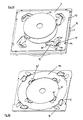
- Fig. 3 shows an adapter and a tray according to the invention.
- an adapter 30 Within tray 5 there is arranged an adapter 30. Its outer surface is formed such that it exactly fits in the opening of the tray 5, including gripping holes 27. For this reason the adapter 30 is provided with radially outwardly extending noses 31. In its radially inward part there are also arranged gripping holes 32 and, at its lower end, support areas 33 which also are reduced in thickness from their radially outwardly end to their inner end. The support areas 33 do not form a complete circle. There is arranged an opening 34 for making possible access from the downside through opening 34 to the radially outwardly area of a disk 25 accommodated on the support areas 33. A similar opening is also arranged in the support area 29 of tray 5, which is not visible here.
- the adapter 30 is insertable and removable from tray 5 in order to be able to accommodate an optical recording medium 25 of lower diameter.
- Fig. 4 shows a bottom view of a container 1 according to the invention.
- the bottom plate 2 is provided with a rectangular depression 35 which depression is about 0.1 mm deep.
- the depression 35 is preferably used to stick a label on it. Because of the depth of the depression and the thickness of the label, which latter is smaller than the former, no additional thickness to the container 1 is added.
- a depression 36 which is also suited for sticking a label on it.
- the thickness of the label is smaller than the depth of the depression 36 so that the size of the container 1 is not increased even if a label is sticked on it.
- the advantage of a label sticked at depression 36 is, that it is visible, even if several containers 1 are stacked together.
- depression 34 of the lowest container 1 in the stack would be visible, whereas all depressions 36 of the stacked containers 1 are visible, and thus all labels arranged there.
- release groove 16 might be moved nearer to the end of side wall 4.
- the dimensions of the outer surfaces of trays 5 and the parts surrounding trays 5 are such that there is only very small open space between trays 5 and surrounding parts. This ensures that it is very unlikely that dust or other particles that might have a disturbing effect may enter into the container 1.
- Fig. 5 shows a top view of the container of Fig. 4.
- a booklet containing information with regard to the optical disks 25 stored within the trays 5, may easily be housed between cover plate 6 and an additional, closed layer 81, and being accessible via opening 80.
- the opening 80 is arranged at the position of the lowermost tray 5, which is not shown here. This has the advantage that the stored item, e.g. the booklet, may be visible through the bottom plate 2. In any case, the stored item does, in this arrangement, not prevent visibility through window 8 onto the disk 25 stored.
- Fig. 6 shows a large container according to the invention.
- the construction of this container 1' is similar to that of Fig. 1.
- On a bottom plate 2 there are arranged side walls 3, 4 the height H of which is much larger than for those of Fig. 1. Accordingly a higher number of trays 5 is stacked between side walls 3, 4. In the example there are stacked 31 trays.
- the cover plate 6 is similar to the one already described.
- Orientation groove 15 and release groove 16 extend over the entire height of the side walls, while identification area 11 keeps similar size as for the container 1 of Fig. 1.
- Holes 36 are used to fix the axes of rotation of levers 21 with which locking and releasing of trays 5 is made possible.
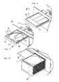
- Fig. 7 shows a magazine type player and/or recorder according to the invention.
- the magazine type player 39 comprises an optical pick-up unit 40, a drawer 41, a magazine tray 42 and a tray moving mechanics 43.
- the optical pick-up unit 40 consists of two mechadecks 44, each of which being equipped with an optical pick-up 45, respective electric motors 46 and other parts usually available on a mechadeck 44 of an optical read/write device, known to the skilled person.
- the drawer 41 is shown in an outward position in which it is possible to manually insert or remove an optical recording medium 25.
- the recording medium 25 is shown in the disk receiving portion of the drawer 41 which is also the tray receiving portion 47.
- the drawer 41 is provided with a guiding slot 48. Through guiding slot 48 a tray 5 may be inserted to or removed from the drawer 41.
- the magazine tray 42 has a base plate 49 on which a front wall 50 and a rear wall 51 are arranged. Between the front wall 50 and the rear wall 51 several containers 1 are stacked one over the other. Walls 50, 51 are provided with guiding ribs 52 in order to guide the containers 1 within the stack. The rear wall 51 further is provided with an orientation rib 53 for making it impossible to insert a container 1 in wrong direction, for example in upside down direction.
- the front wall 50 is provided with a transparent window 54 for enabling a user to directly look at the stacked containers 1, especially at a label attached to depression 36 of a container 1.
- the tray moving mechanics 43 are provided with a slider 45, a pushing element 56 and a motor 57. Further elements and working effect of the tray moving mechanics 43 will be described later on.
- a control unit 58 for controlling working of the different parts of the device and for storing and keeping information about stacked containers 1 and disks contained in the containers 1 as well as means for creating unique codes to be assigned to different containers 1 is also present.
- Fig. 8 shows the left part of a magazine type player according to Fig. 7.
- the drawer 41 is loaded with a cartridge 59 in which an optical recording medium 25 is housed.
- the cartridge 59 is for example a cartridge according to the DVD-RAM standard.
- Fig. 9 shows the left part of a magazine type player 39 similar to the one of Fig. 8 wherein, in this case, the drawer 41 is loaded with a tray 5 according to the invention.
- the tray 5 was inserted into drawer 41 via the guiding slot 48. It is guided within the drawer 41 in guiding grooves (not shown) so that it cannot be removed manually from the drawer 41. It is just possible to remove and insert the disk carried on the tray 5.
- the radially inwardly extending support areas 29 are visible.
- At the bottom of the drawer 41 there is an access hole 60 for enabling access to the optical recording medium 25 from the downside. This access is for example a mechanical access in order to fix the disk position and to rotate the disk 25.
- the orientation holes 28 of tray 5 are placed at the same position as orientation holes 61 of cartridge 59 of Fig. 8, so that the exact position of tray 5 and thus the disk 25 held by the tray 5 is fixed by the same means that also fix the correct position of cartridge 59.
- Fig. 10 shows the right part of the magazine type player of Fig. 7 in a container changing position.
- a magazine tray 42 is shown in its outer position in which the user may access to the containers 1.
- one or several containers 1 may be removed and new containers 1 may be added.
- containers 1 containing three disks each In the figure there are only shown containers 1 containing three disks each. However, it is also possible to stack larger containers into the magazine tray, e.g. 7-tray-containers, 15-tray-containers, 31-tray-containers etc.
- the stack of containers 1 constitutes thus a disk magazine being more compact than already known disk magazines of similar storage capacity.
- Fig. 11 shows a magazine type player having two optical pick-up units 40.
- a top view of the player 39 having two optical pick-up units 40 being arranged at the left and the right side of the magazine tray 42.
- the tray moving mechanics are not shown in this picture.
- On the left hand side there is shown a cross sectional view along line AA.
- the two mechadecks 44 are visible.
- the lower one, which is shown on the right side, comprises a disk motor 62 whereas the other comprises clamping means 63 instead of a disk motor 62.
- Disk motor 62 and clamping means 63 provide for fixing and rotating the disk 25.
- Orientation pins 64 provide for exact positioning of mechadeck 44 relative to drawer 41 and, if available, cartridge 59 or tray 5 being arranged within the tray receiving portion 47 at the drawer 41.
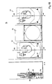
- Fig. 12 shows a container 1 and a tray accessing mechanism of a magazine type player.
- a motor 57 drives a toothed wheel 65, which engages a toothed rack 66 of the slider 55.
- the slider 55 is provided with a push nose 67 for pushing a tray 5 into its rest position within the container 1.
- a pushing element 68 At the other end of slider 55 it is in contact with a pushing element 68.
- Pushing element 68 is of U-shaped form, wherein one leg is in contact with slider 55 while the other leg is positioned in short distance from a tray 5.
- a pressure sensor 69 for sensing if the pushing element 68 is in contact with a tray, bottom plate 2, cover plate 6 or anything else.
- the pushing element 68 is further pre-stressed by a pushing means 70 which is diagrammatically shown to be a spring.
- a movement sensor 71 is diagrammatically shown as a light barrier. In case that pushing element 68 is moved, the light path is blocked and movement sensor 71 indicates that pushing element 68 is moved out of its rest position.
- a pull lever 72 At the left side of slider 55 there is provided a pull lever 72, which is rotatable about an axis 73. At its right end the pull lever 72 is provided with a pulling nose 74 at its lower side, which is not visible here. Pull lever 72 co-acts with a cam 75, when the slider 55 is moved, in order to change the rotational position of pull lever 72.
- Fig. 13 shows the tray accessing mechanism of Fig. 12 during a tray releasing process.
- the slider 55 driven by motor 57 and tooth wheel 65, the slider 55 has moved to the left side.
- This has caused the pushing element 68 to be pushed by pushing means 70 with its one leg into the container 1.
- the pushing element 68 has pushed this tray 5 partly out of the container 1.
- tray 5 is still near to or in contact with push nose 67.
- the leftward movement of slider 55 has caused the pull lever 72 to be pivoted about its axis 73 caused by its interaction with cam 75 (not visible).
- pulling nose 74 is in contact with projection 9 of tray 5.
- the further outward movement of tray 5 is now caused by the movement of pulling nose 74 pulling projection 9 and thereby tray 5 out of the container 1.
- Fig. 14 shows a tray accessing mechanism in a released tray position in which tray 5 is completely removed from container 1.
- Pushing element 68 rests in its position where it is in contact with container 1 while slider 55 has reached its end position.
- the mechadecks 44 which have been pivoted out of their working position in order to make possible accession of tray 5 and disk 25 into the playback position are now moved towards disk 25.
- orientation pins 64 are brought in a position to cooperate with orientation holes 28 in order to assure the exact position of the optical recording medium 25 and disk motor and clamping means 63 come in contact with disk 25.
- the mechadecks 44 are again removed from disk 25 and the inward movement may start.
- slider 55 is moved by the toothed wheel 65 in rightward direction.
- Push nose 67 pushes tray 55, which is guided within guide rails of the magazine tray 42, through guiding slot 48 in direction of the container 1.
- the cross sectional shape of guiding slot 48 is thus that it exactly positions tray 5 vertically in order to exactly enter the opening of container 1.
- Tray 5 is pushed further into container 1 until it reaches its end position in which locking means 20 fix its position.
- pull lever 72 is rotated again into its rest position wherein pulling nose 74 is out of contact with the tray, pushing element 68 is then also pushed back to its rest position.
- the pressure sensor 69 will not sense contact. However, the movement sensor 71 will sense movement of pushing element 68. In this case, the control unit 58 stops the outward movement of slider 55 and makes it move back to its rest position. In case that no tray is available, it is not necessary to move the slider 55 further on.
- tray moving mechanics 43 as well as the optical pick-up unit 40 which both are interconnected to be moved synchronously, are moved upwards or downwards in order to reach the specific trays' position.
- the trays are in predetermined distances from each other, so that stepwise movement of tray moving mechanics should allow for correct positioning with respect to a tray 5.
- orientation grooves 19 make possible to assure the correct position relative to the tray 5 in order to correctly reposition tray moving mechanics 43.
- the container 1 is integral part of the magazine tray 42 and that the optical disk 25 can be automatically moved from the container 1 into its playback position in the device 39.
- a further advantage is, that no additional waste is produced, as packaging in the store is the same as packaging in the magazine type device 39. Apart from container 1, no additional packaging is necessary.
- This container 1 has advantageously small size, comparable to known Jewel boxes, but relatively large storage capacity.
- Figure 15 shows a tray 76 for storing additional items.
- the sides co-acting with side walls 3, 4 of container 1 are identical to those of the disk carrying trays 5 described before. Difference is, that tray 76 has a nearly completely closed bottom plate 77 above which is provided a rectangular space for storing additional items, preferably a booklet relating to one or several of the disks stored in the other trays 5 of a container 1.
- This open space is surrounded by side walls 78 wherein the thickness of the bottom plate 77 is about 1/4 to 1/2 of the height of the side walls 78.
- a hole 79 is provided for accommodating pushing element 68. In case that tray 76 is accessed by the tray moving mechanics 43, it should not be moved out of the container as it does not contain a disk 25.
- Pushing element 68 does not come into contact with tray 76 as it enters the hole 79.
- pressure sensor 69 does not indicate contact while movement sensor 71 indicates movement of pushing element 68.
- control unit 58 indicates, that there is no tray which is to be moved into a replay position. Therefore, the tray moving mechanics 43 is stopped and moved back into its rest position.
- Fig 16 shows a different type of pushing element 82 in top view.
- This pushing element 82 is provided with a first leg 83 for coacting with said slider 55 and with a second leg 84,84' for coacting with said tray 5.
- the second leg 84,84' is arranged such distant from the first leg 83 so that it is able to contact said tray 5 substantially in the middle area of said tray 5.
- the tray 5 is thus pushed at its middle area which reduces the probability of tilt of tray 5 when being pushed out.
- a further advantage lies in the fact that the second leg 84,84', when being inserted into the containerl for pushing out tray 5, acts as a fixing means for a disk 25 being stored in the tray 5 which is arranged below the actually moved out tray 5.
- the second leg 84 has a rounded shape as shown in the figure. It then enters into the opening in which the tray 5 is housed with the full width of the tray 5 so that no opening is left uncovered.
- leg 84' is of small width, similar to the leg of pushing element 68 described above.
- Fig. 17 shows another type of magazine type player according to the invention in a perspective view omitting to show many parts not necessary to be described to a skilled person in detail.
- a container 1 as described in more detail with regard to Fig. 18 is used.
- Middle and lower tray 5 are within the container 1 while the upper tray 5 is removed from the container 1 into the tray receiving portion 47 of the player.
- a slider 55 slideable on a rail 111 is provided with a push-pull element 89 having a pushing nose 112 as pushing element 56 for pushing tray 5 back into the container 1, and a pulling nose 113 for pulling tray 5 out of container 1. Both coact with hook 87 of tray 5.
- Disk 25 is in this view already released from the tray 5 and attached to optical pickup unit 40.
- Disk release pins 95 approach tray 5 from its upper side, coact with swinging type disk holders 108 for urging them to swing downwards. Disk release pins 95 also coact by means of an outwardly extending protjection, not visible here, with holding projection 92 of disk holder 108. Thus disk release pin 95 in this case also acts as tray holder in order to move tray 5 away from disk 25 in order to allow for playback. The downward position of disk holders 108 is shown here. Different types of release pins and disk holders will be described with regard to the following figures.
- Fig. 18 shows, in a perspective view, a different type of container according to the invention. Most parts are similar to those as described above especially with regard to Fig. 1 and therefore not described in detail here.
- Orientation groove 15 is arranged near the front edge 86 of the container.
- the side wall 3 does not extend up to this front edge 86 so that there is a space between bottom plate 2 and cover plate 6.
- the hooks 87 have a slightly inclined face 88 in order to reliably coact with a pulling nose 113 of a push-pull element 89 for removing the tray 5 from container 1.
- Container 1 of this embodiment is provided with orientation grooves 19 at side walls 3,4 in order to provide for correct positioning of container 1 within a magazine or another storing device.
- Orientation grooves 19 as well as connector openings 18 may also be used to seize or grab container 1 in order to move it e.g. into a magazine type player or within such device. Also other openings or recesses of container 1 as e.g. orientation groove 15 may be used therefor.
- Container 1 is further provided with back walls 90 at least partly closing the back side of container 1 which is the visible side in the drawing. Thus the container is open for removal and insertion of trays 5 only at its front side while the opposite side, the back side, is partially closed. Back walls 90 assure higher stability of the container 1. It is to be understood that many of the features described here but not shown in other embodiments described elsewhere in this application may advantageously be incorporated there and vice versa.
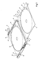
- Fig. 19 shows a perspective view of a tray 5 with rotating type disk holders 91 in holding position, i.e. the disk 25 is held unreleased.
- Holding projections 92 of disk holders 91 extend radially inwardly over the upper part of the outer rim 93 of disk 25 and thus being a disk holding area.
- Lower part of outer rim 93 of disk 25 is supported by a support area 29 of the tray 5 which is not visible in this view.
- Disk holder 91 has a side actuating face 94 being a first actuating face. This side actuating face 94 is provided to coact with a disk release pin 95 being a first actuating means.
- Disk release pin 95 is part of a disk release ring 96 of a magazine type player.
- disk release ring 96 is arranged below a tray holder 97 through holes 98 of which disk release pins 95 extend.
- Pins 95 are in a middle postion of holes 98 in order to fit when brought in contact with tray 5 independent of holders 91 being in holding or releasing position.
- Holders 91 are designed such that opening 105 is always free to receive pins 95 if these are in their middle position of hole 98.
- tray 5 and tray holder 97 are not yet in contact. This positional relation corresponds to a situation where the tray 5 is already removed from the container to tray receiving portion 47 but not yet brought in contact with the tray holder 97.
- Disk holder 91 further has a top actuating face 99 being a second actuating face.
- Top actuating face 99 is manually actuatable e.g. by the fingers of a user in order to release a disk 25 from the tray 5 or to fix a disk 25 at the tray 5.
- Disk holder 91 comprises two arms 100,101 being rigidly connected to one another, or being a single part, and being pivotable with respect to an axis 107 diagramatically indicated in the figure. Actuation of top actuating face 99 allows disk holder 91 to rotate about a certain angle. In the end positions of the rotational movement of disk holder 91 the dimensions of the surrounding parts of the tray 5 are designed such that friction prevents undesired movement of the disk holder 91. Position fixing means is in this case frictional force. Alternatively, not visible in this view, snap connections or other suitable connections may be provided.
- arm 100 is provided with actuation edge 103 and arm 101 is provided with actuation edge 102.
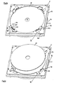
- Fig. 20 shows a perspective view of tray 5 of Fig. 19 with disk holders 91 in holding position. Tray 5 and tray holder 97 are in contact, pins 104 provide for correct orientation and for fixation of tray 5 to tray holder 97.
- Disk release pins 95 extend trough openings 105 between tray 5 and disk 25. Disk release pins 95 are in contact with arms 101 and thus with first actuation edge 102. Release of disk 25 may start by starting rotational movement of disk disk release ring 96. Disk release pins 95 thus start to move in counterclockwise direction, come into contact with actuation edges 103 and thus start rotational movement of disk holder 91 until end position as shown in Fig. 21 is reached.
- Fig. 21 shows tray 5 of Fig. 20 with disk holder 91 in disk release position.
- Tray holder 97 has moved tray 5 away from the playing position of disk 25, for reason of simplicity disk 25 is shown in this position without showing clamping means, pickup means etc. In this remote position, support area 29 of tray 5 is visible.
- Rotatable type disk holders 91 open in radial direction of the disk 25.
- Fig. 22 shows a tray 5 for a small diameter disk 25 in similar state as shown in Fig. 21.
- Rotating type disk holder 91' is arranged rotatably around axis 107'. It has a short first arm 100' and a longer second arm 101'. Pin 95 is in contact with actuation edge 103' while actuation edge 102' will be actuated in order to move holder 91' in its holding position.
- Fig. 23 shows a tray 5 with adapter 106 for a small diameter disk 25.
- Adapter 106 is held and released as a normal diameter disk 25 at tray 5.
- Adapter 106 itself is provided with disk holders 91" which are designed similarly as described above for tray 5. They are actuated by disk release pins similar to pins 95 which are arranged radially inwardly, not visible here.
- Fig. 24 shows a tray 5 with swinging type disk holders 108 in a disk release position.
- Two swinging type disk holders 108 are sufficient to hold the disk 25 as their holding projections 92 extend over a relatively large angle.
- Disk holders 108 are held in their respective position by snap fitting.
- spring operation is provided to urge disk holders 108 in hold position. Springs may therefore be provided in spring recesses 109 as position fixing means. An open position as shown is then possible if disk holders 108 are held open actively.
- Fig. 25 shows a tray 5 with a slightly different type of swinging disk holder 108', also opening in axial direction of the disk 25.
- disk holders 108' are provided, being urged into their holding position by means of spring plates 110 and held in their open position by means of disk release pins 95 being arranged on tray holder 97. These pins 95 are fixed to tray holder 97, no separate movement is necessary. If a user wants to release disk 25 manually, the disk 25 is to be actuated at its inner hole so that its outer rim 93 urges holding projections 92 in order to swing holders 108' to an open position.
- the invention provides for a versatile disk container and magazine player system, allowing to store disks at high density, to give access to disks while preventing disks to unintentionally fall out, to reduce the size of a magazine player and to add the magazine and tray load and unload mechanism to many given types of disk drive, independent of its dimensional properties.
- Elements of container and tray are proposed according to the invention thus to fit within the extremely low height as well as small width and depth dimensions but also provide for reliable, stable, quick and user friendly working.
Landscapes
- Automatic Disk Changers (AREA)
Description
- Fig. 1:
- perspective view of an inventive container;
- Fig. 1A
- Cross sectional view of a part of a container;
- Fig. 2:
- perspective view of partly opened container;
- Fig. 3:
- adapter and tray according to the invention;
- Fig. 4:
- bottom view of inventive container;
- Fig. 5:
- top view of inventive container;
- Fig. 6:
- large container according to the invention;
- Fig. 7:
- magazine type player according to the invention;
- Fig. 8:
- magazine type player loaded with a cartridge;
- Fig. 9:
- magazine type player loaded with tray;
- Fig. 10:
- magazine type player in container changing position;
- Fig. 11:
- magazine type player having two optical pick-up units;
- Fig. 12:
- tray accessing mechanism of a magazine player;
- Fig. 13:
- tray accessing mechanism in tray releasing process;
- Fig. 14:
- tray accessing mechanism in released tray position;
- Fig. 15:
- different type of tray;
- Fig. 16:
- different type of pushing element;
- Fig. 17:
- magazine type player according to the invention;
- Fig. 18:
- different type of container;
- Fig. 19:
- tray with disk holder, unreleased;
- Fig. 20:
- tray with disk holder in holding position;
- Fig. 21:
- tray with disk holder, released;
- Fig. 22:
- tray for small diameter disk;
- Fig. 23:
- tray with adapter for small diameter disk;
- Fig. 24:
- tray with swinging type disk holder;
- Fig. 25:
- tray with different type swinging disk holder.
After
Claims (16)
- Container for optical disks comprising at least one slidable tray (5), guiding means (10) for guiding said tray (5), a cover plate (6) and a bottom plate (2), characterized in that the sum of the thicknesses of said cover plate (6) and said bottom plate (2) equals the thickness of said tray (5) such that the distance between any two trays (5) is an integer multiple of the thickness of said tray (5) if two or more containers (1) are stacked.
- Container according to claim 1, characterized in that it contains three trays (5).
- Container according to one of the preceding claims, characterized in that the outer dimensions of the container (1) substantially equal those of a standard Jewel box or a standard DVD storage box.
- Container according to one of the preceding claims, characterized in that it is open at one side for insertion and removal of the trays (5) and that it is partially closed at the opposite side.
- Container according to one of the preceding claims, characterized in that it comprises a releasable locking means (21) for locking the trays (5) in their position within the container (1).
- Container according to one of the preceding claims, characterized in that it comprises an orientation groove (15).
- Container according to anyone of the preceding claims, characterized in that it contains an identification area (11).
- Container according to one of the preceding claims, characterized in that it comprises a read-write protection means (14).
- Container according to anyone of the preceding claims, characterized in that it is, in top view, of rectangular shape, having first and second base lines (D, W), the first base line (D) being shorter than the second base line (W), the first base line (D) being less than 5% larger than the diameter of the largest optical disk (25) to be stored within the container (1), the second base line (W) being less than 20% larger than the diameter of the largest optical disk (25) to be stored within the container (1), the container (1) having side walls (3, 4) being arranged at the outer ends of the second base line (W) and extending in direction of the first base line (D), the container (1) having openings being arranged between said side walls (3, 4) and extending along the second base line (W), said openings being closed by side surfaces of trays (5) which are accommodated within the container (1), said side surfaces of said trays (5), and surfaces of side walls (3, 4) and end surfaces of bottom plate (2) and cover plate (6) forming a substantially even plane.
- Container according to one of the preceding claims, characterized in that a first locking means (21) is arranged to lock and unlock all of the trays (5) stored within the container (1), and that a second locking means (21) is provided for locking and releasing each single tray (5) independently of the other trays (5).
- A system including a container (1) for optical disks (25) according to one of claims 1-10 and a tray (5), the tray (5) comprising gripping holes (27), a support area (29) for supporting an optical disk (25) at the lower surface of its outer rim, an opening in said support area (29) for enabling access up to the radially outwardly area of an optical disk (25), the upper surface of said support area (29) rising in cross sectional view from its radially inner end to its radially outer end, guiding means (9) for guiding the tray (5) within the container (1), and an orientation hole (28).
- A system including a container (1) for optical disks (25) according to one of claims 1-10 and a tray (5), the tray (5) comprising a support area (29) for supporting an optical disk (25) at the lower surface of its outer rim (93), and a releasable disk holder (91,91',91",108,108') for holding an optical disk (25) at the upper surface of its outer rim (93).
- The system according to claim 11 or 12, further including an adapter for a tray (5), the adapter having an outer shape to fit in said tray (5), gripping holes (32), an inner support area (33) for supporting an optical disk (25) at the lower surface of its outer rim, and an outer support area for being supported by the support area (29) of said tray (5), the upper surface of said inner support area (33) rising in cross sectional view from its radially inner end to its radially outer end, an opening (34) in said support area (33) enabling access to the radially outwardly area of a disk, the adapter being asymmetric.
- A system including a container (1) for optical disks (25) according to one of claims 1-10 and a magazine type player and/or recorder, the magazine type player and/or recorder comprising an optical pick-up unit (40), a magazine tray (42) for accommodating at least one container (1), the magazine tray (42) having an orientation rib (53), and a slider (55) for moving a single tray (5) out of said container (1) into a tray receiving portion (47) of said optical pick-up unit (40), said slider (55) and said optical pick-up unit (40) forming a single vertically movable unit.
- System according to claim 14, characterized in that it comprises a drawer (41) for receiving one of a single disk (25), a cartridge (59), and a tray (5) from a container (1).
- System according to claim 14 or15, characterized in that said tray receiving portion (47) comprises a disk release ring (96) for actuating a disk release pin (95).
Priority Applications (1)
| Application Number | Priority Date | Filing Date | Title |
|---|---|---|---|
| EP01903721A EP1254458B1 (en) | 2000-02-08 | 2001-02-08 | Container for optical disks, tray and magazine type player therefor |
Applications Claiming Priority (4)
| Application Number | Priority Date | Filing Date | Title |
|---|---|---|---|
| WOPCT/EP00/00988 | 2000-02-08 | ||
| EP0000988 | 2000-02-08 | ||
| EP01903721A EP1254458B1 (en) | 2000-02-08 | 2001-02-08 | Container for optical disks, tray and magazine type player therefor |
| PCT/EP2001/001391 WO2001059787A1 (en) | 2000-02-08 | 2001-02-08 | Container for optical disks, tray and magazine type player therefor |
Publications (2)
| Publication Number | Publication Date |
|---|---|
| EP1254458A1 EP1254458A1 (en) | 2002-11-06 |
| EP1254458B1 true EP1254458B1 (en) | 2005-07-20 |
Family
ID=26069181
Family Applications (1)
| Application Number | Title | Priority Date | Filing Date |
|---|---|---|---|
| EP01903721A Expired - Lifetime EP1254458B1 (en) | 2000-02-08 | 2001-02-08 | Container for optical disks, tray and magazine type player therefor |
Country Status (1)
| Country | Link |
|---|---|
| EP (1) | EP1254458B1 (en) |
-
2001
- 2001-02-08 EP EP01903721A patent/EP1254458B1/en not_active Expired - Lifetime
Also Published As
| Publication number | Publication date |
|---|---|
| EP1254458A1 (en) | 2002-11-06 |
Similar Documents
| Publication | Publication Date | Title |
|---|---|---|
| US7227816B2 (en) | Container for optical disks, tray and magazine type player therefor | |
| JP3576095B2 (en) | Auto changer | |
| JPH01119952A (en) | Automatic shutter opening/closing mechanism for disk cartridge in recording and reproducing device | |
| EP0516577B1 (en) | Recording media storage apparatus | |
| EP1258875A1 (en) | Disk magazine system | |
| WO1998014941A1 (en) | Disc cartridge | |
| EP1280146B1 (en) | Scanning device for magazine-type storage medium and method therefor | |
| JPH11306637A (en) | Disk device and disk magazine | |
| EP0833332B1 (en) | Disk drive | |
| JP2000260100A (en) | Disk changer device | |
| EP0811976B1 (en) | Device for the storage, transfer of information carriers | |
| WO1995028710A1 (en) | Disk recording and/or reproduction apparatus and disk recording medium exchanger | |
| CN110024031A (en) | Disc storing unit and disc archive devices | |
| EP1254458A1 (en) | Container for optical disks, tray and magazine type player therefor | |
| JP2524789Y2 (en) | Disc playback device | |
| EP1280145A1 (en) | Method and scanning device for magazine-type storage medium | |
| JP3627264B2 (en) | Disc recording and / or playback device | |
| TW407260B (en) | Recognition device for the recording medium | |
| JP3791531B2 (en) | Disc recording and / or playback device | |
| JPH0514367Y2 (en) | ||
| JPH05189912A (en) | Disk cartridge and device therefor | |
| JPH1125569A (en) | Disc changer | |
| JPH0935391A (en) | Cartridge and tray and automatic media changer | |
| JP2000195138A (en) | Stopper device for stocker of recording medium | |
| JPH1027449A (en) | Disk holder and disk case |
Legal Events
| Date | Code | Title | Description |
|---|---|---|---|
| PUAI | Public reference made under article 153(3) epc to a published international application that has entered the european phase |
Free format text: ORIGINAL CODE: 0009012 |
|
| 17P | Request for examination filed |
Effective date: 20020726 |
|
| AK | Designated contracting states |
Kind code of ref document: A1 Designated state(s): AT BE CH CY DE DK ES FI FR GB GR IE IT LI LU MC NL PT SE TR |
|
| AX | Request for extension of the european patent |
Free format text: AL;LT;LV;MK;RO;SI |
|
| 17Q | First examination report despatched |
Effective date: 20030331 |
|
| RBV | Designated contracting states (corrected) |
Designated state(s): DE FR GB IT |
|
| GRAP | Despatch of communication of intention to grant a patent |
Free format text: ORIGINAL CODE: EPIDOSNIGR1 |
|
| GRAS | Grant fee paid |
Free format text: ORIGINAL CODE: EPIDOSNIGR3 |
|
| GRAA | (expected) grant |
Free format text: ORIGINAL CODE: 0009210 |
|
| AK | Designated contracting states |
Kind code of ref document: B1 Designated state(s): DE FR GB IT |
|
| REG | Reference to a national code |
Ref country code: GB Ref legal event code: FG4D |
|
| REF | Corresponds to: |
Ref document number: 60112043 Country of ref document: DE Date of ref document: 20050825 Kind code of ref document: P |
|
| RAP2 | Party data changed (patent owner data changed or rights of a patent transferred) |
Owner name: THOMSON LICENSING |
|
| REG | Reference to a national code |
Ref country code: GB Ref legal event code: 746 Effective date: 20050912 |
|
| ET | Fr: translation filed | ||
| PLBE | No opposition filed within time limit |
Free format text: ORIGINAL CODE: 0009261 |
|
| STAA | Information on the status of an ep patent application or granted ep patent |
Free format text: STATUS: NO OPPOSITION FILED WITHIN TIME LIMIT |
|
| 26N | No opposition filed |
Effective date: 20060421 |
|
| PGFP | Annual fee paid to national office [announced via postgrant information from national office to epo] |
Ref country code: IT Payment date: 20080227 Year of fee payment: 8 |
|
| PGFP | Annual fee paid to national office [announced via postgrant information from national office to epo] |
Ref country code: DE Payment date: 20090219 Year of fee payment: 9 |
|
| PGFP | Annual fee paid to national office [announced via postgrant information from national office to epo] |
Ref country code: FR Payment date: 20090219 Year of fee payment: 9 |
|
| PGFP | Annual fee paid to national office [announced via postgrant information from national office to epo] |
Ref country code: GB Payment date: 20100201 Year of fee payment: 10 |
|
| REG | Reference to a national code |
Ref country code: FR Ref legal event code: ST Effective date: 20101029 |
|
| PG25 | Lapsed in a contracting state [announced via postgrant information from national office to epo] |
Ref country code: FR Free format text: LAPSE BECAUSE OF NON-PAYMENT OF DUE FEES Effective date: 20100301 |
|
| PG25 | Lapsed in a contracting state [announced via postgrant information from national office to epo] |
Ref country code: DE Free format text: LAPSE BECAUSE OF NON-PAYMENT OF DUE FEES Effective date: 20100901 |
|
| PG25 | Lapsed in a contracting state [announced via postgrant information from national office to epo] |
Ref country code: IT Free format text: LAPSE BECAUSE OF NON-PAYMENT OF DUE FEES Effective date: 20090208 |
|
| GBPC | Gb: european patent ceased through non-payment of renewal fee |
Effective date: 20110208 |
|
| PG25 | Lapsed in a contracting state [announced via postgrant information from national office to epo] |
Ref country code: GB Free format text: LAPSE BECAUSE OF NON-PAYMENT OF DUE FEES Effective date: 20110208 |