EP1253814A2 - Heat insulation structure of electric junction box - Google Patents
Heat insulation structure of electric junction box Download PDFInfo
- Publication number
- EP1253814A2 EP1253814A2 EP02100378A EP02100378A EP1253814A2 EP 1253814 A2 EP1253814 A2 EP 1253814A2 EP 02100378 A EP02100378 A EP 02100378A EP 02100378 A EP02100378 A EP 02100378A EP 1253814 A2 EP1253814 A2 EP 1253814A2
- Authority
- EP
- European Patent Office
- Prior art keywords
- heat
- junction box
- board
- section
- electric junction
- Prior art date
- Legal status (The legal status is an assumption and is not a legal conclusion. Google has not performed a legal analysis and makes no representation as to the accuracy of the status listed.)
- Granted
Links
Images


Classifications
-
- H—ELECTRICITY
- H05—ELECTRIC TECHNIQUES NOT OTHERWISE PROVIDED FOR
- H05K—PRINTED CIRCUITS; CASINGS OR CONSTRUCTIONAL DETAILS OF ELECTRIC APPARATUS; MANUFACTURE OF ASSEMBLAGES OF ELECTRICAL COMPONENTS
- H05K7/00—Constructional details common to different types of electric apparatus
- H05K7/02—Arrangements of circuit components or wiring on supporting structure
- H05K7/026—Multiple connections subassemblies
-
- H—ELECTRICITY
- H05—ELECTRIC TECHNIQUES NOT OTHERWISE PROVIDED FOR
- H05K—PRINTED CIRCUITS; CASINGS OR CONSTRUCTIONAL DETAILS OF ELECTRIC APPARATUS; MANUFACTURE OF ASSEMBLAGES OF ELECTRICAL COMPONENTS
- H05K1/00—Printed circuits
- H05K1/02—Details
- H05K1/0201—Thermal arrangements, e.g. for cooling, heating or preventing overheating
-
- H—ELECTRICITY
- H05—ELECTRIC TECHNIQUES NOT OTHERWISE PROVIDED FOR
- H05K—PRINTED CIRCUITS; CASINGS OR CONSTRUCTIONAL DETAILS OF ELECTRIC APPARATUS; MANUFACTURE OF ASSEMBLAGES OF ELECTRICAL COMPONENTS
- H05K2201/00—Indexing scheme relating to printed circuits covered by H05K1/00
- H05K2201/06—Thermal details
- H05K2201/062—Means for thermal insulation, e.g. for protection of parts
-
- H—ELECTRICITY
- H05—ELECTRIC TECHNIQUES NOT OTHERWISE PROVIDED FOR
- H05K—PRINTED CIRCUITS; CASINGS OR CONSTRUCTIONAL DETAILS OF ELECTRIC APPARATUS; MANUFACTURE OF ASSEMBLAGES OF ELECTRICAL COMPONENTS
- H05K2201/00—Indexing scheme relating to printed circuits covered by H05K1/00
- H05K2201/09—Shape and layout
- H05K2201/09818—Shape or layout details not covered by a single group of H05K2201/09009 - H05K2201/09809
- H05K2201/09972—Partitioned, e.g. portions of a PCB dedicated to different functions; Boundary lines therefore; Portions of a PCB being processed separately or differently
Definitions
- the present invention relates to a heat insulation structure of an electric junction box, as well as to a heat insulation structure for protecting control components from heat-generating components in an electric junction box which houses the control components and the heat-generating components mounted on a board.
- PCB printed circuit board
- the heat generated by the relay 31 is transferred to a CPU 33, which is a control component, by way of a Cu trace laid on the board 32.
- a CPU 33 which is a control component
- the temperature of the CPU 33 increases.
- an ECU mounted in an engine compartment involves a risk of the CPU 33 being subjected to a temperature higher than a guaranteed temperature.
- a conceivable countermeasure against this problem is use of a component having a high guaranteed temperature as the CPU 33. In this case, the cost of the CPU is greatly increased.
- the present invention aims at providing a heat insulation structure of an electric junction box which enables mounting of a control component and a heat-generating component on a single substrate while avoiding adverse thermal effects on the control component from the heat-generating component at low cost, and which enables space savings by means of incorporating the heat-generating component into the electric junction box.
- the invention is characterized by having the following arrangement.
- the convection-of-air prevention wall brought in contact with the conduction prevention section on the board inhibits convection of air across the conduction prevention section within the electric junction box.
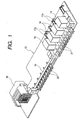
- Fig. 1 is a perspective view showing a board to which a heat insulation structure of an electric junction box according to one embodiment of the invention is applied; and Fig. 2 is a plan view showing only the board shown in Fig. 1.
- Fig. 3 is a perspective view showing a relay box shown in Fig. 2 from its back side; and Fig. 4 is a substantially-longitudinal cross-sectional view showing the electric junction box having the substrate shown in Fig. 1 incorporated therein.
- an electric junction box 10 comprises an upper cover 11 and a lower cover 12.
- a control component such as a CPU, and heat-generating components such as relays 14, which are to be mounted on a board 13 such as a PCB, are housed within an internal space defined between the upper cover 11 and the lower cover 12.
- the plurality of relays 14 are mounted on the board 13 through a relay block 15, and the heat generated by the relays 14 is not conducted directly to the board 13.
- a relay terminal 16 of each relay 14 is connected to a bus bar 17 provided in the relay block 15, by means of fusing or hot-soldering.
- Relay coils are connected to the board 13 by way of a bus bar extension 17a which extends from the bus bar 17 substantially in the form of the letter L.
- a width W3 of the conduction prevention section in a direction perpendicular to a direction of connecting the conduction prevention section with the mounting section is smaller than a width W4 of the mounting section, so that the heat generated by the relays 14 on the mounting section 13b is difficult to be conducted to the control section 18.
- a strip-shaped conduction prevention section A having a predetermined width W1 is provided in the board 13, between a control section 13a into which a control part is to be mounted and the relay mounting section 13b. No Cu trace is provided in the conduction prevention section A, and only a wiring assembly (i.e. , a signal line) 18 is provided in the conduction prevention section A.
- the conduction prevention section A minimizes heat conduction which arises in the Cu trace and reduces conduction of heat from the relays 14 to the control component to a minimum.
- a convection-of-air prevention wall 19 is provided integrally on an interior surface of the upper cover 11 of the electric junction box 10, and another convection-of-air prevention wall 19 is provided integrally on an interior surface of the lower cover 12 of the same, in which the walls 19 vertically pair up with each other with the board 13 sandwiched therebetween, as shown in Fig. 4. Distal ends 19a of the respective convection-of-air prevention walls 19 are brought into contact with a mount inhibition area B having a predetermined with W2 within the conduction prevention section A of the board 13, thereby preventing occurrence of convection of air across the conduction prevention section A in the electric junction box 10.
- reference numeral 20 designates a signal connector; and 21 designates a wiring terminal to be brought into contact with an electric wire (not shown).
- the convection-of-air prevention walls 19 brought in contact with the conduction prevention section A on the board 13 inhibit occurrence of convection of air across the conduction prevention section A from the relays 14 to the control component (i.e., from the right side to the left side in Fig. 2).
- heat-generating components such as the relays 14 are mounted on the board 13 through the relay block 15, and the conduction prevention section A is provided on the board 13, between the control component and the relays 14.
- the convection-of-air prevention wall 19 is provided on the interior surface of the upper cover 11 constituting the electric junction box 10 while being brought in contact with the mount inhibition area B within the conduction prevention section A on the board 13.
- control component and the relays 14 can be mounted on the single board 13 without involvement of a heat problem.
- the present invention is not limited to the embodiment set forth and is susceptible to modification or alterations, as required.
- the material, geometry, dimensions, patterns, number, and locations of the heat-generating components, those of the substrate, those of the conduction prevention section, those of the upper cover, these of the lower cover, and those of the convection-of-air prevention walls described in the embodiment can be set arbitrarily and are not limited.
- heat-generating components are mounted on a board while being grouped into a plurality of blocks.
- a conduction prevention section is defined between a control component and heat-generating components, which are to be mounted on a board.
- heat-generating components are mounted on a board while being grouped into a plurality of blocks.
- a conduction prevention section is defined between a control component and heat-generating components, which are to be mounted on a board.
- Convection-of-air prevention walls brought in contact with the conduction prevention section on the board prevent occurrence of convection of air across the conduction prevention section within the electric junction box.
Landscapes
- Engineering & Computer Science (AREA)
- Microelectronics & Electronic Packaging (AREA)
- Cooling Or The Like Of Electrical Apparatus (AREA)
- Connection Or Junction Boxes (AREA)
Abstract
Description
a control section on which a control component is mounted,
a mounting section on which a plurality of heat-generating components are mounted, and
a conduction prevention section defined between the control section and the mounting section.
the electric junction box is constituted by upper and lower covers, and
the upper and lower covers are provided with convection-of-air prevention walls brought into contact with the conduction prevention section, respectively, so that the convection-of-air prevention walls prevent occurrence of convection of air across the conduction prevention section.
Claims (5)
- A heat insulation structure comprising:an electric junction box; anda board housed in the electric junction box, including,
a control section on which a control component is mounted,
a mounting section on which a plurality of heat-generating components are mounted, and
a conduction prevention section defined between the control section and the mounting section. - The heat insulation structure according to claim 1, wherein
the electric junction box is constituted by upper and lower covers, and
the upper and lower covers are provided with convection-of-air prevention walls brought into contact with the conduction prevention section, respectively, so that the convection-of-air prevention walls prevent occurrence of convection of air across the conduction prevention section. - The heat insulation structure according to claim 1, wherein the plurality of heat-generating components are relays.
- The heat insulation structure according to claim 3, wherein the relays are mounted on the mounting section through a relay block.
- The heat insulation structure according to claim 1, wherein a width of the conduction prevention section in a direction perpendicular to a direction of connecting the conduction prevention section with the mounting section is smaller than that of the mounting section.
Applications Claiming Priority (2)
| Application Number | Priority Date | Filing Date | Title |
|---|---|---|---|
| JP2001132767 | 2001-04-27 | ||
| JP2001132767A JP3954321B2 (en) | 2001-04-27 | 2001-04-27 | Heat conduction prevention structure of electrical junction box |
Publications (3)
| Publication Number | Publication Date |
|---|---|
| EP1253814A2 true EP1253814A2 (en) | 2002-10-30 |
| EP1253814A3 EP1253814A3 (en) | 2003-12-10 |
| EP1253814B1 EP1253814B1 (en) | 2007-05-30 |
Family
ID=18980730
Family Applications (1)
| Application Number | Title | Priority Date | Filing Date |
|---|---|---|---|
| EP02100378A Expired - Lifetime EP1253814B1 (en) | 2001-04-27 | 2002-04-16 | Heat insulation structure of electric junction box |
Country Status (4)
| Country | Link |
|---|---|
| US (1) | US20020159225A1 (en) |
| EP (1) | EP1253814B1 (en) |
| JP (1) | JP3954321B2 (en) |
| DE (1) | DE60220334T2 (en) |
Cited By (3)
| Publication number | Priority date | Publication date | Assignee | Title |
|---|---|---|---|---|
| WO2005055687A1 (en) * | 2003-12-05 | 2005-06-16 | Renk Aktiengesellschaft | Cooling device for electrical power units of electrically operated vehicles |
| US9113557B2 (en) | 2007-11-27 | 2015-08-18 | Yazaki Europe Limited | Junction box |
| CN115244810A (en) * | 2020-03-24 | 2022-10-25 | 住友电装株式会社 | Electrical connection box |
Families Citing this family (8)
| Publication number | Priority date | Publication date | Assignee | Title |
|---|---|---|---|---|
| JP2005012991A (en) * | 2003-05-26 | 2005-01-13 | Fuji Electric Hi-Tech Corp | Ac adapter |
| JP4360404B2 (en) * | 2004-03-18 | 2009-11-11 | 三菱電機株式会社 | Control device using module heat dissipation structure |
| KR100822115B1 (en) | 2006-08-09 | 2008-04-15 | 미쓰비시덴키 가부시키가이샤 | Heat dissipation structure of module and control device using it |
| US7983050B2 (en) * | 2007-07-17 | 2011-07-19 | Chrysler Group Llc | Pluggable system for reading inputs, controlling outputs and communicating with another module for power distribution unit |
| JP5808703B2 (en) * | 2012-03-21 | 2015-11-10 | 日立オートモティブシステムズ株式会社 | Electronic control unit |
| US20140168905A1 (en) * | 2012-12-16 | 2014-06-19 | Energy Pro Technology Co., Ltd. | Electric box with wire protection mechanism |
| US20150083376A1 (en) * | 2013-09-25 | 2015-03-26 | Google Inc. | Cold-formed sachet modified atmosphere packaging |
| JP2015088629A (en) * | 2013-10-31 | 2015-05-07 | 日立オートモティブシステムズ株式会社 | Electronic control device |
Family Cites Families (3)
| Publication number | Priority date | Publication date | Assignee | Title |
|---|---|---|---|---|
| DE4121545A1 (en) * | 1991-06-28 | 1993-01-07 | Hella Kg Hueck & Co | Lamp current monitoring appts. for motor vehicle - provides spatial and thermal separation between heat generation components and heat sensitive components |
| DE4436547A1 (en) * | 1994-10-13 | 1996-04-18 | Telefunken Microelectron | Housing for electronic modules mounted on circuit board for insertion in motor vehicles |
| JP3052843B2 (en) * | 1996-07-03 | 2000-06-19 | 住友電装株式会社 | Electrical junction box |
-
2001
- 2001-04-27 JP JP2001132767A patent/JP3954321B2/en not_active Expired - Fee Related
-
2002
- 2002-04-16 DE DE60220334T patent/DE60220334T2/en not_active Expired - Lifetime
- 2002-04-16 EP EP02100378A patent/EP1253814B1/en not_active Expired - Lifetime
- 2002-04-26 US US10/132,293 patent/US20020159225A1/en not_active Abandoned
Cited By (4)
| Publication number | Priority date | Publication date | Assignee | Title |
|---|---|---|---|---|
| WO2005055687A1 (en) * | 2003-12-05 | 2005-06-16 | Renk Aktiengesellschaft | Cooling device for electrical power units of electrically operated vehicles |
| US7616443B2 (en) | 2003-12-05 | 2009-11-10 | Renk Aktiengesellschaft | Cooling device for electrical power units of electrically operated vehicles |
| US9113557B2 (en) | 2007-11-27 | 2015-08-18 | Yazaki Europe Limited | Junction box |
| CN115244810A (en) * | 2020-03-24 | 2022-10-25 | 住友电装株式会社 | Electrical connection box |
Also Published As
| Publication number | Publication date |
|---|---|
| EP1253814B1 (en) | 2007-05-30 |
| DE60220334T2 (en) | 2008-02-07 |
| EP1253814A3 (en) | 2003-12-10 |
| JP2002330523A (en) | 2002-11-15 |
| DE60220334D1 (en) | 2007-07-12 |
| JP3954321B2 (en) | 2007-08-08 |
| US20020159225A1 (en) | 2002-10-31 |
Similar Documents
| Publication | Publication Date | Title |
|---|---|---|
| US7160118B2 (en) | Electric junction box | |
| EP1253814B1 (en) | Heat insulation structure of electric junction box | |
| EP0931703B1 (en) | Switch box, particularly for a vehicle | |
| JPH09139264A (en) | Multi-pole connector for PCB | |
| CN101902022A (en) | Junction boxes for vehicles | |
| JP2014057390A (en) | Electric connection box | |
| US7335035B2 (en) | Electric junction box | |
| US7351911B2 (en) | Connection box | |
| JP2006320147A (en) | Electrical junction box | |
| US6643134B2 (en) | Holding and heat dissipation structure for heat generation part | |
| JP3955717B2 (en) | Engine integrated control device and circuit body used therefor | |
| JP4128702B2 (en) | Electrical junction box | |
| JP5367669B2 (en) | Electrical junction box for vehicles | |
| JP2002374607A (en) | Wiring structure of bus-bar in electric junction box | |
| JP3056462B2 (en) | Switchboard | |
| JP3108608B2 (en) | Electrical junction box | |
| JP3308874B2 (en) | Busbar structure of electrical junction box | |
| JP7391468B2 (en) | Vehicle relay module | |
| JPH09233649A (en) | Electric junction box | |
| KR200388110Y1 (en) | Junction box | |
| JPH0756567Y2 (en) | Electrical junction box | |
| JP2002159119A (en) | Electrical junction box | |
| CN111629515B (en) | Busbar system | |
| EP1239715A2 (en) | Holding and heat dissipation structure for heat generation part | |
| JP3167951B2 (en) | Heat dissipation structure of large current wiring pattern |
Legal Events
| Date | Code | Title | Description |
|---|---|---|---|
| PUAI | Public reference made under article 153(3) epc to a published international application that has entered the european phase |
Free format text: ORIGINAL CODE: 0009012 |
|
| AK | Designated contracting states |
Kind code of ref document: A2 Designated state(s): AT BE CH CY DE DK ES FI FR GB GR IE IT LI LU MC NL PT SE TR |
|
| AX | Request for extension of the european patent |
Free format text: AL;LT;LV;MK;RO;SI |
|
| PUAL | Search report despatched |
Free format text: ORIGINAL CODE: 0009013 |
|
| AK | Designated contracting states |
Kind code of ref document: A3 Designated state(s): AT BE CH CY DE DK ES FI FR GB GR IE IT LI LU MC NL PT SE TR |
|
| AX | Request for extension of the european patent |
Extension state: AL LT LV MK RO SI |
|
| RIC1 | Information provided on ipc code assigned before grant |
Ipc: 7B 60R 16/02 B Ipc: 7H 05K 1/02 B Ipc: 7H 05K 7/02 A |
|
| 17P | Request for examination filed |
Effective date: 20040525 |
|
| AKX | Designation fees paid |
Designated state(s): DE FR GB |
|
| 17Q | First examination report despatched |
Effective date: 20050630 |
|
| GRAP | Despatch of communication of intention to grant a patent |
Free format text: ORIGINAL CODE: EPIDOSNIGR1 |
|
| GRAS | Grant fee paid |
Free format text: ORIGINAL CODE: EPIDOSNIGR3 |
|
| GRAA | (expected) grant |
Free format text: ORIGINAL CODE: 0009210 |
|
| AK | Designated contracting states |
Kind code of ref document: B1 Designated state(s): DE FR GB |
|
| RAP1 | Party data changed (applicant data changed or rights of an application transferred) |
Owner name: YAZAKI CORPORATION |
|
| REG | Reference to a national code |
Ref country code: GB Ref legal event code: FG4D |
|
| REF | Corresponds to: |
Ref document number: 60220334 Country of ref document: DE Date of ref document: 20070712 Kind code of ref document: P |
|
| ET | Fr: translation filed | ||
| PLBE | No opposition filed within time limit |
Free format text: ORIGINAL CODE: 0009261 |
|
| STAA | Information on the status of an ep patent application or granted ep patent |
Free format text: STATUS: NO OPPOSITION FILED WITHIN TIME LIMIT |
|
| 26N | No opposition filed |
Effective date: 20080303 |
|
| PGFP | Annual fee paid to national office [announced via postgrant information from national office to epo] |
Ref country code: GB Payment date: 20140416 Year of fee payment: 13 |
|
| PGFP | Annual fee paid to national office [announced via postgrant information from national office to epo] |
Ref country code: FR Payment date: 20140409 Year of fee payment: 13 Ref country code: DE Payment date: 20140430 Year of fee payment: 13 |
|
| REG | Reference to a national code |
Ref country code: DE Ref legal event code: R119 Ref document number: 60220334 Country of ref document: DE |
|
| GBPC | Gb: european patent ceased through non-payment of renewal fee |
Effective date: 20150416 |
|
| PG25 | Lapsed in a contracting state [announced via postgrant information from national office to epo] |
Ref country code: DE Free format text: LAPSE BECAUSE OF NON-PAYMENT OF DUE FEES Effective date: 20151103 Ref country code: GB Free format text: LAPSE BECAUSE OF NON-PAYMENT OF DUE FEES Effective date: 20150416 |
|
| REG | Reference to a national code |
Ref country code: FR Ref legal event code: ST Effective date: 20151231 |
|
| PG25 | Lapsed in a contracting state [announced via postgrant information from national office to epo] |
Ref country code: FR Free format text: LAPSE BECAUSE OF NON-PAYMENT OF DUE FEES Effective date: 20150430 |