EP1253612A2 - Switch relay with switching status display - Google Patents
Switch relay with switching status display Download PDFInfo
- Publication number
- EP1253612A2 EP1253612A2 EP02008245A EP02008245A EP1253612A2 EP 1253612 A2 EP1253612 A2 EP 1253612A2 EP 02008245 A EP02008245 A EP 02008245A EP 02008245 A EP02008245 A EP 02008245A EP 1253612 A2 EP1253612 A2 EP 1253612A2
- Authority
- EP
- European Patent Office
- Prior art keywords
- arm
- armature
- switch relay
- switch
- display element
- Prior art date
- Legal status (The legal status is an assumption and is not a legal conclusion. Google has not performed a legal analysis and makes no representation as to the accuracy of the status listed.)
- Withdrawn
Links
Images



Classifications
-
- H—ELECTRICITY
- H01—ELECTRIC ELEMENTS
- H01H—ELECTRIC SWITCHES; RELAYS; SELECTORS; EMERGENCY PROTECTIVE DEVICES
- H01H50/00—Details of electromagnetic relays
- H01H50/08—Indicators; Distinguishing marks
-
- H—ELECTRICITY
- H01—ELECTRIC ELEMENTS
- H01H—ELECTRIC SWITCHES; RELAYS; SELECTORS; EMERGENCY PROTECTIVE DEVICES
- H01H51/00—Electromagnetic relays
- H01H51/22—Polarised relays
-
- H—ELECTRICITY
- H01—ELECTRIC ELEMENTS
- H01H—ELECTRIC SWITCHES; RELAYS; SELECTORS; EMERGENCY PROTECTIVE DEVICES
- H01H9/00—Details of switching devices, not covered by groups H01H1/00 - H01H7/00
- H01H9/16—Indicators for switching condition, e.g. "on" or "off"
Definitions
- the invention relates to an electromagnetic switch relay and more particularly to such a relay having a visual indicator.
- Switch relays are used in a variety of technical fields and particularly in the automotive industry. Switch relays exist in a variety of structural forms.
- published patent application DE 19 920 742 A1 shows an electromagnetic relay having a base, a magnet system and an armature spring, in which the magnet system has an armature on which two lever sections are integrally formed.
- the lever sections form support points for the armature spring.
- a further support point for the armature spring is located on a fixed relay part. By bending the fixed relay part, the armature and thus a contact spacing may be adjusted.
- switch state closed or open
- the contact arrangements may be checked through a viewing window in the relay housing.
- the contact spacing is constructed to be large enough so that when the switch contact is open, it's state is visually recognisable.
- This construction has the disadvantage, however, that the contacts have to be arranged in the vicinity of a viewing window in the housing and moreover that the contact spacing when the contact is open must be made sufficiently large.
- An object of the invention is therefore to provide an electromagnetic switch relay where the switching status is more readily recognisable.
- Another object of the invention is to provide a display element for a switch relay for the purpose of displaying the switch position of the switch relay.
- the switch relay according to the invention has a display element which is mounted movably, is in operative connection with the switch contact and is movable in dependence on the position of the switch contact from a rest position to a display position.
- a mechanical display element provides the advantage that a clearly visible display of the switching status is possible regardless of the position of the contact elements.
- the display element provides the possibility of converting a small change in the contact spacings or a small change in the position of the armature into a clear alteration in the position of the display element, by way of the display element. This makes it possible to recognise the switching status of the switch relay simply, on the basis of a clear alteration in the position of the display element.
- the display element is not connected directly to the switch contact, but is in operative connection with a component whereof the position is dependent on the position of the switch contact.
- the display element is in operative connection with the armature or an armature spring.
- a flexible connection point having a pointer is included in the display element to enlarge the movement of the contact or armature. This makes a clearer display of the switch position possible.
- the deflection of the switch contact is enlarged by way of a lever action and is converted to a larger deflection of the pointer or display element.
- Figure 1 shows the main components of a switch relay 1, having the housing removed.
- the switch relay 1 has a magnet coil 4 positioned over a magnet core 6.
- a yoke 7 is positioned below the magnet coil 4 and abuts against a permanent magnet 32.
- the magnet core 6 lies over the permanent magnet 32.
- the yoke 7 projects beyond the magnet coil 4 and serves as an abutment face for an armature plate 21 ( Figure 2).
- the yoke 7 has at the left-hand end a holding plate 17 which is stamped into a Z shape.
- An armature spring 9 is secured to a first spring plate 18 on the upper side of the holding plate 17.
- the first spring plate 18 is angled upwards above the magnet coil 4 and is joined to a second spring plate 19.
- the second spring plate 19 is aligned substantially parallel to the upper side of the magnet coil 4 and extends to the right-hand end of the magnet coil 4. At the right-hand end of the magnet coil 4, the second spring plate 19 extends to a curved region 31.
- a third spring plate 20 extends from the curved region 31 and is arranged substantially parallel to the terminating face of the magnet coil 4.
- the button 10 which is mounted in the housing (not illustrated) of the switch relay 1.
- the button 10 has a central push surface which is connected by way of a resilient bellows to a fixed outer frame.
- the outer frame is mounted in the housing.
- the central push surface can be pressed downwards, by manual actuation, in the direction of the second spring plate 19 so that the spring plate 19 is pressed downwards.
- the magnet coil 4 has electrical terminals 5 for triggering. Furthermore, a first and a second load terminal 2, 3 are provided which extend laterally below the yoke 7 and are conductively connected to one another or isolated from one another in dependence on the switch position of the switch relay 1.
- a display element 11 Arranged on a right-hand longitudinal side of the magnet coil 4 is a display element 11 which has a holding element 12, a first and a second arm 13, 14 and a display face 15.
- the holding element 12 is connected to the yoke 7.
- the holding element 12 is connected by way of a first resilient connection piece 39 to the first arm 13.
- the first arm 13 extends substantially perpendicularly from the yoke 7 upwards to below the second spring plate 19.
- the display face 15 is constructed at the end of the first arm 13 and extends laterally above the magnet coil 4.
- the second spring plate 19 has a display opening 16 over the display face 15.
- Figure 1 shows the display face 15 in a first position.
- the second arm 14 is connected to the first arm 13 by way of a second resilient connection piece 41 and is arranged substantially parallel to the first arm 13.
- the second arm 14 has a receiving region 28 which is made in the form of a slot.
- the second spring plate 19 is pushed into the receiving region 28 so that if there is a change in the vertical position of the second spring plate 19 the second arm 14 and thus the first arm 13 are also moved.
- This means that the display element 11 is clamped between the yoke 7 and the second spring plate 19.
- the position of the yoke 7 is fixed, so the position of the display face 15 depends only on the vertical position of the second spring plate 19.
- the spring arm 14 is also pressed downwards. Because of the linking of the second arm 14 to the first arm 13, a force is initiated at the lower end of the first arm 13, so that the arm 13 is pulled downwards and at the same time the first flexible connection piece 39 is bent downwards. As a consequence of this, the display face 15 is tilted down and to the right. Because of the length of the first arm 13, a small change in height in the second spring plate 19 is translated into a relatively large lateral pivotal movement of the display face 15. In the first position, the display face 15 is preferably inclined somewhat with respect to the planar surface of the second spring plate 19.
- Figure 2 shows a perspective view of the switch relay 1 from below.
- the shape of the first and second load terminals 2, 3 can clearly be seen, respectively opening out into a first and second contact piece 22, 23, each extending parallel below the right-hand end of the magnet coil 4.
- An electrically conductive contact bridge 24 is arranged above the ends of the first and second contact pieces 22, 23 and represents the switch contact.
- the contact bridge 24 is held on opposing sides by a first and a second spring arm 25, 26 of a spring contact.
- the first and second spring arms 25, 26 respectively have in the end region a first and a second angled end piece 29, 30 extending behind the armature plate 21.
- the armature plate 21 lies on the first and second end regions 29, 30 by means of a first and second support region 35, 36.
- the armature plate 21 is connected to the third spring plate 20 by way of rivets. In the rest position, the armature plate 21 is kept in an upper position, so the contact bridge 24 is also raised away from the first and second contact pieces 22, 23 by the spring force of the spring contact arms 25, 26. In this position, the first and second contact pieces 22, 23 are electrically isolated from one another. If the button 10 is now pressed downwards, then at the same time the second spring plate 19 and the third spring plate 20 are pressed downwards. As a consequence of this, the armature plate 21 is also moved downwards. The armature plate 21 presses the first and second spring arms 25, 26 downwards by means of the first and second support regions 35, 36 until the contact bridge 24 lies on the upper sides of the first and second contact pieces 22, 23.
- the first and second load terminals 2, 3 are electrically connected to one another.
- the second arm 14 is also pressed downwards and because of the resilient mounting of the first arm 13 the first arm 13 is tilted in the direction of the armature plate 21. Consequently, the display face 15 is pivoted out of a display region provided and is preferably moved below the second spring plate 19.
- FIG 3 shows a cross-section through the switch relay 1, in which once again the shape of the display element 11 is clearly visible.
- the switch relay 1 is illustrated without the load terminals 2, 3 and the first and second contact pieces 22, 23.
- the position illustrated corresponds to a closed switching status of the relay.
- the contact bridge 24 is pressed downwards by way of the spring arms 25, 26.
- On the underside the contact bridge 24 has a contact block 34 which serves to improve the contact made by the first and second contact pieces 22, 23.
- the first and second spring arms 25, 26 extend as far as the center of the magnet coil 4 and are connected to the yoke 7 on the underside of the yoke 7.
- the alignment of the first and second spring arms 25, 26 is such that the contact bridge 24 is held in an upper position in which the contact bridge 24 is raised away from the first and second contact pieces 22, 23.
- the first and second spring arms 25, 26 are pressed downwards in the direction of the first and second contact pieces 22, 23, as illustrated in Figure 3.
- the armature plate 21 has a holding lug 37 on an inner side, and this projects out of the surface of the armature plate 21.
- the holding lug 37 is constructed in such a way that the armature plate 21 which was pressed downwards by manual actuation of the button 10 is on the one hand pulled by the spring contact 9 in the direction of the magnet coil 4 and is held in the lower position by the holding lug 7, which reaches below the yoke 7.
- the holding lug 37 in the lower position, abuts against the underside of the yoke 7 and hence prevents the armature plate 21 from being moved back upwards.
- the contact bridge lies in the lower position, on the first and second contact pieces 22, 23.
- Figure 3A is a diagrammatic cross-sectional illustration showing the armature plate 21 in the lower position, in which two holding lugs 37 are arranged below the yoke 7 and prevent upward movement of the armature plate 21.
- the magnet coil 4 is supplied with current.
- the magnet coil 4 consequently generates a magnetic field which counters the magnetic field of the permanent magnet and thus reduces the magnetic force acting on the armature plate 21. Consequently, the armature plate 21 is pulled away from the yoke 7 by the armature spring 9.
- the holding lugs 37 are moved in front of the yoke 7, so that upward movement of the armature plate 21 is made possible. Because the armature spring 9 is preloaded upwards, the armature plate 21 is moved upwards into an upper position.
- FIG 4 shows a further sectional illustration of the switch relay 1, in which a housing 38 surrounding the switch relay 1 is illustrated.
- the armature plate 21 is located in the lower position in which the armature plate 21 is kept below the yoke 7 by the holding lug 37.
- the armature plate 21 is pre-tensioned in the direction of the yoke 7 by the magnetic field of the permanent magnet.
- the pre-tensioning force of the armature spring 9 in the direction away from the yoke 7 is smaller than the force of attraction of the permanent magnet.
- a viewing window 40 is made in the housing 38 above the display opening 16.
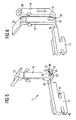
- FIG. 5 shows, in an enlarged perspective illustration, the display element 11.
- the display element 11 is made in a simple construction from a synthetic material. Synthetic material is particularly suitable for constructing the first connection piece 39, which although it should ensure a determined rest position of the arm 13 should also enable a tilting movement of the arm 13. These resilient properties are provided by a large number of types of synthetic. Moreover, the production of the display element 11 from synthetic offers the advantage that the display element 11 is low in mass and so changes the contact dynamics little.
- the holding element 12 has a first and a second holding recess 43, 44.
- the first and second holding recesses 43, 44 are made on opposing sides on the short side edges of the holding element 12.
- parts of the surface of the yoke 7 are inserted into the first and second holding recesses 43, 44 so that the holding element 12 is fixedly connected to the yoke 7.
- the upper part of the holding element 12 is made in the form of a preferably square bar which extends to the first connection piece 39.
- the first connection piece 39 preferably has the same width as the holding element 12 but a perceptibly smaller height than the bar of the holding element 12. Because of this sizing, a tilting movement is made possible in the plane of the longitudinal direction of the bar of the holding element 12.
- the plane of the tilting movement is indicated in Figure 5 by a double-headed arrow.
- the first connection piece 39 extends to the arm 13.
- the lower end region has a second receiving region 45 opposite the connection to the first connection piece 39.
- the second receiving region 45 has in cross-section a narrow opening region 51 which opens into a larger receiving space 52.
- the opening region is made on the side of the arm 13, arranged opposite the connection region of the first connection piece 39.
- Two holding edges 53 oppose one another in the opening region 51 and delimit the opening region 51. The spacing between the holding edges 53 is selected such that a connection element 46 pushed into the second receiving region 45 is held by the two holding edges.
- the receiving space is sized to be large enough for pivoting of the arm 13 to be possible without movement of the inserted connection element 46 being hindered.
- the armature spring 9 is used as the connection element.
- any other connection element to the switch contact 24 it is also possible for any other connection element to the switch contact 24 to be used.
- the arm 13 is preferably of wider construction in the lower region than in the upper region.
- the wider construction makes it possible to improve the coupling between the first arm 13 and the connection element 46, which is for example as illustrated in the preceding figures in the form of the armature spring 9.
- the central region of the first arm 13 may have a smaller cross-section for adequate rigidity.
- the cross-section of the first arm 13 becomes larger again in order to keep the even larger display face 15 stable. If the connection element 46 is moved upwards, the first arm 13 pivots in the direction of the holding element 12.
- Figure 6 shows a second embodiment of the display element 11.
- the first connection piece 39 is constructed in a lower region of the bar of the holding element 12 and, in a lower end region, extends to a first end web 47 of the first arm 13.
- the lower end of the first arm 13 has a second end web 41 by way of which the first arm 13 is connected to the second arm 14.
- the first and second end webs 47, 41 are separated from one another by a slot 42 which is made from below in the lower end of the first arm 13.
- the second arm 14 is arranged substantially parallel to the first arm 13.
- the second arm 14 has a first receiving region 28 in the upper end region, constructed in a manner corresponding to the second receiving region 45.
- the first arm 13 ends in the display face 15, also in the region of the second receiving region 45.
- the display face 15 has a preferably rectangular shape and extends, starting from the first arm 13, in a direction perpendicular to the first arm 13 into the plane of the drawing. The alignment of the display face 15 extends to above the magnet coil
- connection element 46 is inserted into the first receiving region 28 in the assembled condition, as illustrated in Figure 5. If the connection element moves upwards, the second arm 14 is also moved upwards and hence the first arm 13 is tilted in a pivotal movement in the direction of the holding element 12. If the connection element 45 is moved downwards, the second arm 14 is also moved downwards and the first arm 13 is tilted away from the holding element 12. During the tilting movements, there is a flexing in the region of the first connection piece 39.
- the first connection piece 39 is constructed in accordance with the embodiments of the display elements 11 of Figures 5 and 6 in such a way that a rest position of the first arm or of the first and second arms is determined.
- the first connection piece 39 is preferably constructed as a film hinge.
- Figure 7 shows a further embodiment of a switch relay which has a display element 11 corresponding in its essential parts to the display element of Figure 5.
- the button 10 is not illustrated.
- the second spring plate 19 is bent into an actuation strip 49 which extends downwards in the direction of the second receiving region 45.
- the actuation strip 49 is bent in its end region in the direction of the second receiving region 45 and by means of the end region is pushed into the second receiving region 45. In this way, it becomes possible to transmit the alteration in the vertical position of the second spring plate 19 downwards onto the second receiving region 45.
- Figure 8 shows a cross-section through the display element 11 of Figure 7, which has a second holding element 48.
- the second holding element 48 is arranged substantially parallel to the first arm 13 and has a cover surface 50 in the upper region.
- the cover surface 50 extends in the lateral direction, starting from the second holding element 48, like the display face 15.
- the central region of the second holding element 48 is shaped in such a way that the central region is pushed laterally onto the side face of the magnet coil 4 and hence the second holding element 48 is held fixedly in its position.
- the second spring plate 19 has a display opening 16, with the cover plate 50 being constructed to match the display opening 16 and covering a partial region of the display opening 16.
- the display element 15 is arranged in front of the cover plate 50 in the installed condition and is thus visible from above.
- FIG. 7 corresponds to the condition in which the switch relay is connected to be conductive. If the armature plate 21 is moved upwards out of the lower position by a corresponding supply of current to the magnet coil 4 and a corresponding action of the armature spring 9, then the vertical position of the second spring plate 19 and the vertical position of the lower end of the actuation strip 49 are also moved upwards. As a consequence of this, the first arm 13 is tilted in the direction of the second holding element 48 and the cover surface 15 is preferably moved completely below the cover plate 50. This means that the display face 15 is no longer visible from above. Consequently, the altered switch position of the relay is shown in a visually readily recognisable manner.
- the embodiment of the display element 11 and the switch relay 1 illustrated in Figures 7 and 8 has the advantage that no second arm 14 is required and that preferably there is pre-positioning of the cover plate 50 and the display face 15.
- the display element 11 has, besides the display face 15, the cover plate 50 which covers the cover face 15 when the first arm 13 is in a predetermined pivot position.
- the display element enlarges the display stroke so that a contact movement is more readily visible.
- the principle is based on the elongation of a pointer of the flexing line of a film hinge.
- the contact dynamics are reduced by only a small extent.
Landscapes
- Physics & Mathematics (AREA)
- Electromagnetism (AREA)
- Breakers (AREA)
- Switch Cases, Indication, And Locking (AREA)
- Push-Button Switches (AREA)
- Displays For Variable Information Using Movable Means (AREA)
Abstract
Description
Claims (21)
- A switch relay (1) having a switch contact (24), in which the switch contact (24) connects two terminals (2, 3) electrically to one another in dependence on two switch positions, characterised in that a display element (11) is provided, such that it is mounted movably in operative connection with the switch contact (24) and is pivotal in dependence on the position of the switch contact (24) from a rest position to a display position.
- A switch relay according to Claim 1, characterised in that the display element (11) is mounted by a flexible connection point (39).
- A switch relay according to Claim 2, characterised in that the display element (11) has a holding element (12), an arm (13) and a display face (15), the holding element (12) being fixedly connected to the switch relay (1) and connected by way of the flexible connection point (39) to one end of the arm (13), and the display face (15) is arranged at the other end of the arm (13).
- A switch relay according to one of Claims 1 to 3, characterised in that the display element (11) is in operative connection with an armature (21) by way of a spring element (9).
- A switch relay according to Claim 4, characterised in that the spring element (9) is constructed in the form of a pre-tensioning spring and in that the pre-tensioning spring is clamped between the switch relay and the armature (21) and exerts a pre-tensioning force on the armature (21) in the direction of a rest position.
- A switch relay according to Claim 4, characterised in that the spring element (9) is inserted into a receiving opening (45) in the display element (11),
in that in dependence on the position of the armature (21) the spring element (9) adopts different vertical positions, and
in that the different vertical positions effect tilting of the display element (11). - A switch relay according to one of Claims 1 to 6, characterised in that the display element (11) has a second arm (14),
in that the second arm (14) is secured to the first arm (13), and
in that the second arm (14) is in operative connection with the spring element (9). - A switch relay according to Claim 7, characterised in that the second arm (14) is connected to the first end of the first arm (13).
- A switch relay according to one of Claims 7 or 8, characterised in that the second arm (14) is arranged substantially in a plane with the first arm (13).
- A switch relay according to one of Claims 7 to 9, characterised in that the second arm (14) is connected at a second end to a connection element (46), in particular a spring element (9) which is in operative connection with the armature (21).
- A switch relay according to one of Claims 1 to 10, characterised in that
an actuation means (10) is provided,
in that the actuation means (10) is in operative connection with an armature (21), and
in that the actuation means (10) allows the armature (21) to be moved into a closed position (make-contact position) in which a contact element (24) in operative connection with the armature (21) makes contact with the terminals (2, 3) and connects them in electrically conductive manner. - A switch relay according to Claim 11, characterised in that a holding mechanism (7, 37, 32) which keeps the armature (21) in the closed position is provided, and
in that a detaching mechanism (4, 9) is provided whereof the actuation allows the armature (21) to be moved from the closed position to the rest position. - A switch relay according to Claim 12, characterised in that the holding mechanism is constructed in the form of a projection (37) on the inside of the armature (21), and in the closed position the projection reaches behind an abutment edge of the yoke (7) and keeps the armature in the closed position.
- A switch relay according to Claim 12 or 13, characterised in that the detaching mechanism is constructed in the form of a pre-tensioning spring (9) which forcibly urges the armature (21) away from the magnet core (6), and in that, when the current supply is switched on, the magnet coil (4) generates a countering magnetic field which weakens the magnetic field of the permanent magnet (32) so that the pre-tensioning spring (9) can pull the armature (21) away from the magnet core (6) and the armature (21) can pivot into the rest position in which the contact element (24) is raised away from the terminals (2, 3).
- A mechanical display element (11) for a switch relay (1) for the purpose of displaying a switch position of the switch relay, having an arm (13), a display face (15) and a holding element (12), in which the arm (13) has the display face (15),
in which the arm (13) is connected to the holding element (12),
in which the holding element (12) is provided for the purpose of securing the display element (11) to the switch relay (1),
in which the arm (13) has a point of introduction (28, 45) which is provided for the purpose of introducing a switching movement of the switch relay (1),
and in which the holding element (12) is connected to the arm (13) by way of a flexible connection point (39). - A display element according to Claim 15, characterised in that the arm (13) is connected to a second arm (14), and
in that the second arm (14) has a point of introduction (28) for the purpose of introducing a switching movement. - A display element according to Claim 16, characterised in that the second arm (14) is connected to the first arm (13) in the region of the flexible connection point (39).
- A display element according to Claim 15, characterised in that the point of introduction (45) of the arm (13) is arranged in the region of the connection point (39).
- A display element according to one of Claims 15 to 18, characterised in that the point of introduction (28, 45) is constructed as a recess.
- A display element according to one of Claims 15 to 19, characterised in that the two arms (13, 14) are arranged substantially parallel to one another.
- A display element according to one of Claims 16, 17, 19 and 20, characterised in that the second arm (14) is connected at one end to the first arm (13) and has the point of introduction (28) at the second end.
Applications Claiming Priority (2)
| Application Number | Priority Date | Filing Date | Title |
|---|---|---|---|
| DE10120452 | 2001-04-26 | ||
| DE10120452 | 2001-04-26 |
Publications (2)
| Publication Number | Publication Date |
|---|---|
| EP1253612A2 true EP1253612A2 (en) | 2002-10-30 |
| EP1253612A3 EP1253612A3 (en) | 2005-04-20 |
Family
ID=7682801
Family Applications (1)
| Application Number | Title | Priority Date | Filing Date |
|---|---|---|---|
| EP02008245A Withdrawn EP1253612A3 (en) | 2001-04-26 | 2002-04-18 | Switch relay with switching status display |
Country Status (6)
| Country | Link |
|---|---|
| US (1) | US6674348B2 (en) |
| EP (1) | EP1253612A3 (en) |
| JP (1) | JP2003016899A (en) |
| KR (1) | KR20020083441A (en) |
| CN (1) | CN1383172A (en) |
| BR (1) | BR0201409A (en) |
Cited By (1)
| Publication number | Priority date | Publication date | Assignee | Title |
|---|---|---|---|---|
| EP1471555A3 (en) * | 2003-04-24 | 2006-07-05 | Omron Corporation | Electromagnetic relay |
Families Citing this family (6)
| Publication number | Priority date | Publication date | Assignee | Title |
|---|---|---|---|---|
| US7630989B2 (en) | 2002-05-17 | 2009-12-08 | Colonial First State Investments Ltd. | Transaction management system |
| JP4158590B2 (en) * | 2003-04-24 | 2008-10-01 | オムロン株式会社 | Electromagnetic relay |
| JP4140432B2 (en) * | 2003-04-24 | 2008-08-27 | オムロン株式会社 | Electromagnetic relay |
| ES2829373T3 (en) * | 2018-01-16 | 2021-05-31 | Microelettrica Scientifica Spa | Contactor device |
| DE102018109864B4 (en) * | 2018-04-24 | 2021-09-02 | Phoenix Contact Gmbh & Co. Kg | relay |
| DE102019117802A1 (en) * | 2019-07-02 | 2021-01-07 | Johnson Electric Germany GmbH & Co. KG | Switching contact system of a switching device operated by electrical current |
Family Cites Families (8)
| Publication number | Priority date | Publication date | Assignee | Title |
|---|---|---|---|---|
| DE2717020C2 (en) * | 1977-04-18 | 1984-04-26 | Brown, Boveri & Cie Ag, 6800 Mannheim | Electrical switching device, in particular motor protection switches |
| EP0001317A1 (en) * | 1977-07-16 | 1979-04-04 | Ranco Incorporated | Motion transmitting lever-device comprising a plastic hinge |
| FR2579016B1 (en) * | 1985-03-18 | 1988-09-09 | Telemecanique Electrique | ELECTROMAGNETICALLY CONTROLLED SWITCH |
| JPH0614385Y2 (en) * | 1986-05-28 | 1994-04-13 | 和泉電気株式会社 | Operation display device for electromagnetic relay |
| JPH0821298B2 (en) * | 1986-12-27 | 1996-03-04 | オムロン株式会社 | Relay |
| JPH0723875Y2 (en) * | 1987-09-04 | 1995-05-31 | オムロン株式会社 | Relay with operation display |
| IT233985Y1 (en) * | 1994-07-29 | 2000-02-16 | Gavazzi Carlo Electromatic | MINIATURE MULTI-CONTACT ELECTROMAGNETIC RELAY FOR INDUSTRIAL USES |
| DE19920742C2 (en) | 1999-05-05 | 2001-05-31 | Tyco Electronics Logistics Ag | Electromagnetic relay |
-
2002
- 2002-04-18 EP EP02008245A patent/EP1253612A3/en not_active Withdrawn
- 2002-04-19 CN CN02116135A patent/CN1383172A/en active Pending
- 2002-04-23 US US10/128,761 patent/US6674348B2/en not_active Expired - Lifetime
- 2002-04-24 KR KR1020020022415A patent/KR20020083441A/en not_active Withdrawn
- 2002-04-24 BR BR0201409-2A patent/BR0201409A/en not_active IP Right Cessation
- 2002-04-26 JP JP2002125871A patent/JP2003016899A/en not_active Withdrawn
Cited By (1)
| Publication number | Priority date | Publication date | Assignee | Title |
|---|---|---|---|---|
| EP1471555A3 (en) * | 2003-04-24 | 2006-07-05 | Omron Corporation | Electromagnetic relay |
Also Published As
| Publication number | Publication date |
|---|---|
| CN1383172A (en) | 2002-12-04 |
| KR20020083441A (en) | 2002-11-02 |
| BR0201409A (en) | 2003-06-10 |
| EP1253612A3 (en) | 2005-04-20 |
| JP2003016899A (en) | 2003-01-17 |
| US20030001703A1 (en) | 2003-01-02 |
| US6674348B2 (en) | 2004-01-06 |
Similar Documents
| Publication | Publication Date | Title |
|---|---|---|
| CA2054271C (en) | Electromagnetic relay | |
| US10879630B2 (en) | Conductor connection terminal | |
| EP3089190B1 (en) | Electromagnetic relay | |
| EP2835813B1 (en) | Contact mechanism and electromagnetic relay | |
| GB2383469A (en) | Relay | |
| US11043347B2 (en) | Electromagnetic relay | |
| KR20010051224A (en) | Electromagnetic relay | |
| EP1298691A1 (en) | Electromagnetic relay | |
| US6674348B2 (en) | Switch relay with switching status display | |
| CN112912985B (en) | Contact device | |
| EP1592036B1 (en) | Electromagnetic relay | |
| KR20010012264A (en) | Relay with contact springs | |
| EP0817230A1 (en) | Electromagnetic contactor | |
| US8026782B2 (en) | Magnet system for an electrical actuator | |
| JP5448693B2 (en) | Electromagnetic relay | |
| US7538646B2 (en) | Relay with reduced leakage current | |
| JP4116022B2 (en) | Electromagnetic relay | |
| EP1672660B1 (en) | Electromagnetic relay | |
| IE950039A1 (en) | Blade assembly | |
| CN210136820U (en) | Relay and anti-shaking armature thereof | |
| US5886600A (en) | Modular thermal magnetic trip unit for rapid circuit interruption | |
| EP4336538A1 (en) | Electromagnet device and electromagnetic relay | |
| JP6789316B2 (en) | Thin relay cradle, cradle assembly, and relay | |
| EP1081732A2 (en) | Electromagnetic relay | |
| EP1271593A2 (en) | Relay |
Legal Events
| Date | Code | Title | Description |
|---|---|---|---|
| PUAI | Public reference made under article 153(3) epc to a published international application that has entered the european phase |
Free format text: ORIGINAL CODE: 0009012 |
|
| AK | Designated contracting states |
Kind code of ref document: A2 Designated state(s): AT BE CH CY DE DK ES FI FR GB GR IE IT LI LU MC NL PT SE TR |
|
| AX | Request for extension of the european patent |
Free format text: AL;LT;LV;MK;RO;SI |
|
| PUAL | Search report despatched |
Free format text: ORIGINAL CODE: 0009013 |
|
| AK | Designated contracting states |
Kind code of ref document: A3 Designated state(s): AT BE CH CY DE DK ES FI FR GB GR IE IT LI LU MC NL PT SE TR |
|
| AX | Request for extension of the european patent |
Extension state: AL LT LV MK RO SI |
|
| AKX | Designation fees paid | ||
| STAA | Information on the status of an ep patent application or granted ep patent |
Free format text: STATUS: THE APPLICATION IS DEEMED TO BE WITHDRAWN |
|
| 18D | Application deemed to be withdrawn |
Effective date: 20051021 |
|
| REG | Reference to a national code |
Ref country code: DE Ref legal event code: 8566 |