EP1253580A1 - Foot pedal for drums - Google Patents
Foot pedal for drums Download PDFInfo
- Publication number
- EP1253580A1 EP1253580A1 EP02009167A EP02009167A EP1253580A1 EP 1253580 A1 EP1253580 A1 EP 1253580A1 EP 02009167 A EP02009167 A EP 02009167A EP 02009167 A EP02009167 A EP 02009167A EP 1253580 A1 EP1253580 A1 EP 1253580A1
- Authority
- EP
- European Patent Office
- Prior art keywords
- foot pedal
- rotation shaft
- tension coil
- coil spring
- adjustment screw
- Prior art date
- Legal status (The legal status is an assumption and is not a legal conclusion. Google has not performed a legal analysis and makes no representation as to the accuracy of the status listed.)
- Granted
Links
- 230000005540 biological transmission Effects 0.000 claims description 3
- 238000006073 displacement reaction Methods 0.000 description 4
- 239000000314 lubricant Substances 0.000 description 4
- XAGFODPZIPBFFR-UHFFFAOYSA-N aluminium Chemical compound [Al] XAGFODPZIPBFFR-UHFFFAOYSA-N 0.000 description 2
- 229910052782 aluminium Inorganic materials 0.000 description 2
- 230000000994 depressogenic effect Effects 0.000 description 2
- 241000208967 Polygala cruciata Species 0.000 description 1
- 238000010009 beating Methods 0.000 description 1
- 230000008602 contraction Effects 0.000 description 1
- 230000000881 depressing effect Effects 0.000 description 1
- 230000000694 effects Effects 0.000 description 1
- 238000000034 method Methods 0.000 description 1
- 230000000087 stabilizing effect Effects 0.000 description 1
Images



Classifications
-
- G—PHYSICS
- G10—MUSICAL INSTRUMENTS; ACOUSTICS
- G10D—STRINGED MUSICAL INSTRUMENTS; WIND MUSICAL INSTRUMENTS; ACCORDIONS OR CONCERTINAS; PERCUSSION MUSICAL INSTRUMENTS; AEOLIAN HARPS; SINGING-FLAME MUSICAL INSTRUMENTS; MUSICAL INSTRUMENTS NOT OTHERWISE PROVIDED FOR
- G10D13/00—Percussion musical instruments; Details or accessories therefor
- G10D13/10—Details of, or accessories for, percussion musical instruments
- G10D13/11—Pedals; Pedal mechanisms
Definitions
- This invention relates to foot pedals that are depressed by feet of players to strike drums by beater heads.
- the foot pedals use tension springs to apply return characteristics to beaters and the like.
- Foot pedals are arranged for drum sets to allow players to depress them with their feet.
- a beater is correspondingly revolved or moved towards a drum (e.g., a bass drum) so that a beater head (or mallet) strikes it to produce a corresponding drum sound.
- a drum e.g., a bass drum
- a beater head or mallet
- FIG. 4 shows the basic structure of the conventional foot pedal unit for use in the drum set.
- a pair of beaters 1 are attached to a rotation shaft 2, which is pivotally and rotatably supported by upper ends of a pair of support poles 3.
- the tip end of a foot pedal 4 (whose upper portion is only illustrated in FIG. 4) is interconnected to the prescribed position of the rotation shaft 2 between the attached positions of the beaters 1 by means of a transmission member 5 such as a chain or a plate-like member.
- a tension coil spring 6 is provided to apply a return characteristic to the foot pedal 4 so that the foot pedal 4 is automatically returned to its original position.
- One tension coil spring 6 can be arranged to engage with one end of the rotation shaft 2, or a pair of tension coil springs 6 can be arranged to engage with both ends of the rotation shaft 2, which is shown in FIG. 4.
- the upper end 6A of the tension coil spring 6 is hung on a roller 9, which is rotatably supported by a crank arm 7, via a link member 8.
- the lower end 6B of the tension coil spring 6 is hung in a through hole 10A of an adjustment screw 10, which is used to adjust the tension of the tension coil spring 6.
- FIG. 5 shows the detailed structure around the adjustment screw 10 that is connected with the lower end 6B of the tension coil spring 6 via the through hole 10A.
- the adjustment screw 10 engages with a nut 11, which is rotatably supported by a support hole 13.
- the base portion of the support hole 13 is arranged at a bracket 12 that is an integral part of the support pole 3 and is horizontally projected from the support pole 3.
- a tapped hole 14 is formed to horizontally and partially penetrate through the bracket 12 in such a way that it rectangularly crosses the axial direction of the support hole 13.
- a fastening bolt 15 for fixing the nut 11 at the prescribed position is engaged with the tapped hole 14. Therefore, by merely revolving the nut 11 in a clockwise or counterclockwise direction, the adjustment screw 10 ascends up or descends down so that the tension of the tension coil spring 6 can be adjusted.
- the player depresses the foot pedal 4 with his/her foot to cause a certain revolution of the rotation shaft 2 by means of the transmission member 5, so that the beaters 1 are forced to move towards the drumhead of the bass drum and the like.
- the tip ends of the crank arms 7 correspondingly revolve to slightly ascend up.
- the tension coil springs 6 whose upper ends 6A are hung on the rollers 9 by the link members 8 are expanded to cause increases of their tensions, which in turn cause the increase of the load imparted to the beaters 1 and the foot pedal 4 via the rotation shaft 2.
- this causes displacements in the lower ends 6B of the tension coil springs 6, so that some friction may occur in the through holes 10A of the adjustment screws 10.
- the lower ends 6B of the tension coil springs 6 are directly hung on the through holes 10A of the adjustment screws 10, wherein there are provided very small contact areas between the lower ends 6B and the through holes 10A. That is, very large contact resistances occur therebetween because high loads are concentrated on the small contact areas. This may cause unpleasant noise during the playing of the drums. In addition, this may provide a bad influence to the player's operation of the pedal.
- a lubricant may be effective to solve such drawbacks.
- This invention provides a foot pedal unit for use in a drum set that comprises a beater, a rotation shaft, a pair of support poles for rotatably supporting the rotation shaft, and a foot pedal connected to the rotation shaft.
- the foot pedal unit provides an automatic return structure that comprises a tension coil spring whose upper end is connected to a crank arm at one end of the rotation shaft via a first roller, an adjustment screw that is manually adjusted in height, and a second roller by which the lower end of the tension coil spring is connected with the adjustment screw.
- the beater and foot pedal are automatically returned to their initial positions without causing unwanted friction or noise at the lower end of the tension coil spring that is extended or contracted when the player depresses the foot pedal with his/her foot because the second roller substantially absorbs the positional displacement of the lower end of the tension coil spring.
- the lower end of the tension coil spring is connected with the second roller that is held by a holder attached to the adjustment screw.
- the adjustment screw engages with a nut that is fixed to a bracket, which is projected and formed as an integral part of the support pole.
- FIGS 1 and 2 show essential parts of a foot pedal unit in accordance with one embodiment of the invention, wherein the parts identical to those shown in Figures 4 and 5 are designated by the same reference numerals; hence, the detailed description thereof will be omitted as necessary.
- reference numeral 3 designates a support pole that is formed by the aluminum die cast. Similar to the aforementioned foot pedal unit shown in FIG. 4, there are provided a pair of the 'aluminum' support poles 3 on both sides of the foot pedal 4. The rotation shaft 2 is pivotally supported by the upper ends of the support poles 3.
- the present embodiment is characterized by providing a brand-new automatic return structure at one end or each of both ends of the rotation shaft 2.
- a crank arm 7 is fixed to one end of the rotation shaft 2, and a roller 9 is rotatably supported by the tip end of the crank arm 7.
- a tension coil spring 6 is provided relative to the support pole 3 in order to apply a return characteristic to the foot pedal 4.
- the upper end 6A of the tension coil spring 6 is hung on the roller 9 by means of a link member 8.
- a bracket 12 is formed as an integral part of the support pole 3 at its base portion.
- a nut 11 is attached to the bracket 12 in accordance with the foregoing structure shown in FIG. 5.
- a holder 16 is attached to the tip end of an adjustment screw 10, so that a roller 17 is rotatably supported by the holder 16.
- the lower end 6B of the tension coil spring 6 is hung on the roller 17 by means of a link member 18.
- the rotation shaft 2 revolves every time the player depresses the foot pedal 4 with his/her foot, wherein the crank arm 7 is correspondingly revolved so that its tip end automatically ascends up.
- the roller 9 attached to the tip end of the crank arm 7 moves upwards to expand the tension coil spring 6 against its tension (or contraction) while guiding the link member 8 outwardly from the support pole 3, which is shown in FIG. 3.
- the tension coil spring 6 is slightly inclined from its initial vertical position with respect to the fulcrum corresponding to the roller 17.
- the positional displacement is substantially absorbed by the revolution of the roller 17, which in turn avoids occurrence of contact friction with respect to the lower end 6B of the tension coil spring 6.
- the present embodiment provides a completely novel foot pedal unit for use in the drum set, wherein even though a small positional displacement occurs at the lower end of the tension coil spring due to the player's operation of the foot pedal, it can be reliably absorbed by the revolution of the roller that is attached to the lower end of the tension coil spring. Therefore, it is possible to reliably avoid occurrence of unpleasant noise during the performance of the drum set equipped with the foot pedal unit.
- substantially no resistance is additionally applied to the player's operation of the pedal because of the 'smooth' revolution of the roller. Therefore, it is possible to provide noticeable effects for stabilizing the drum performance using the foot pedal.
- the present embodiment employs the holder 16 and roller 17 for avoiding unwanted friction and noise at the lower end of the tension coil spring 6.
- this invention is not necessarily limited to use the aforementioned elements 16 and 17.
- the present embodiment is designed in such a way that the lower end of the tension coil spring is directly connected to the roller. In order to ensure the smooth movement of the roller, it is possible to additionally provide a bearing.
Landscapes
- Physics & Mathematics (AREA)
- Engineering & Computer Science (AREA)
- Acoustics & Sound (AREA)
- Multimedia (AREA)
- Auxiliary Devices For Music (AREA)
- Electrophonic Musical Instruments (AREA)
Abstract
Description
- This invention relates to foot pedals that are depressed by feet of players to strike drums by beater heads. In particular, the foot pedals use tension springs to apply return characteristics to beaters and the like.
- Foot pedals are arranged for drum sets to allow players to depress them with their feet. When a player depresses the foot pedal with his/her foot, a beater is correspondingly revolved or moved towards a drum (e.g., a bass drum) so that a beater head (or mallet) strikes it to produce a corresponding drum sound. Conventionally, there are provided various types of structures and methods for improvements in the performability of the foot pedal for use in the drum set.
- FIG. 4 shows the basic structure of the conventional foot pedal unit for use in the drum set. Herein, a pair of
beaters 1 are attached to arotation shaft 2, which is pivotally and rotatably supported by upper ends of a pair ofsupport poles 3. The tip end of a foot pedal 4 (whose upper portion is only illustrated in FIG. 4) is interconnected to the prescribed position of therotation shaft 2 between the attached positions of thebeaters 1 by means of a transmission member 5 such as a chain or a plate-like member. Atension coil spring 6 is provided to apply a return characteristic to the foot pedal 4 so that the foot pedal 4 is automatically returned to its original position. Onetension coil spring 6 can be arranged to engage with one end of therotation shaft 2, or a pair oftension coil springs 6 can be arranged to engage with both ends of therotation shaft 2, which is shown in FIG. 4. Herein, theupper end 6A of thetension coil spring 6 is hung on aroller 9, which is rotatably supported by acrank arm 7, via alink member 8. Thelower end 6B of thetension coil spring 6 is hung in a through hole 10A of anadjustment screw 10, which is used to adjust the tension of thetension coil spring 6. - FIG. 5 shows the detailed structure around the
adjustment screw 10 that is connected with thelower end 6B of thetension coil spring 6 via the through hole 10A. Theadjustment screw 10 engages with anut 11, which is rotatably supported by asupport hole 13. The base portion of thesupport hole 13 is arranged at abracket 12 that is an integral part of thesupport pole 3 and is horizontally projected from thesupport pole 3. A tappedhole 14 is formed to horizontally and partially penetrate through thebracket 12 in such a way that it rectangularly crosses the axial direction of thesupport hole 13. A fasteningbolt 15 for fixing thenut 11 at the prescribed position is engaged with the tappedhole 14. Therefore, by merely revolving thenut 11 in a clockwise or counterclockwise direction, theadjustment screw 10 ascends up or descends down so that the tension of thetension coil spring 6 can be adjusted. - In the musical performance using the drums equipped with the aforementioned foot pedal unit, the player depresses the foot pedal 4 with his/her foot to cause a certain revolution of the
rotation shaft 2 by means of the transmission member 5, so that thebeaters 1 are forced to move towards the drumhead of the bass drum and the like. Accompanied with the revolution of therotation shaft 2, the tip ends of thecrank arms 7 correspondingly revolve to slightly ascend up. Hence, thetension coil springs 6 whoseupper ends 6A are hung on therollers 9 by thelink members 8 are expanded to cause increases of their tensions, which in turn cause the increase of the load imparted to thebeaters 1 and the foot pedal 4 via therotation shaft 2. In addition, this causes displacements in thelower ends 6B of thetension coil springs 6, so that some friction may occur in the through holes 10A of theadjustment screws 10. - In the conventional foot pedal unit, the
lower ends 6B of thetension coil springs 6 are directly hung on the through holes 10A of theadjustment screws 10, wherein there are provided very small contact areas between thelower ends 6B and the through holes 10A. That is, very large contact resistances occur therebetween because high loads are concentrated on the small contact areas. This may cause unpleasant noise during the playing of the drums. In addition, this may provide a bad influence to the player's operation of the pedal. A lubricant may be effective to solve such drawbacks. However, there are provided small effective areas of the lubricant between thetension coil springs 6 and theadjustment screws 10. Hence, the lubricant may be run out in a relatively short period of time. Thus, it is difficult to demonstrate the effectiveness of the use of the lubricant to overcome the aforementioned drawbacks. - It is an object of the invention to provide a foot pedal unit that ensures a smooth operation for a pedal for beating a bass drum when depressed with a player's foot, while avoiding occurrence of unpleasant noise due to mechanical contacts between an adjustment screw and a tension coil spring repeatedly extended or contracted during playing of the bass drum.
- This invention provides a foot pedal unit for use in a drum set that comprises a beater, a rotation shaft, a pair of support poles for rotatably supporting the rotation shaft, and a foot pedal connected to the rotation shaft. The foot pedal unit provides an automatic return structure that comprises a tension coil spring whose upper end is connected to a crank arm at one end of the rotation shaft via a first roller, an adjustment screw that is manually adjusted in height, and a second roller by which the lower end of the tension coil spring is connected with the adjustment screw. Due to the provision of the automatic return structure, the beater and foot pedal are automatically returned to their initial positions without causing unwanted friction or noise at the lower end of the tension coil spring that is extended or contracted when the player depresses the foot pedal with his/her foot because the second roller substantially absorbs the positional displacement of the lower end of the tension coil spring.
- In the above, the lower end of the tension coil spring is connected with the second roller that is held by a holder attached to the adjustment screw. In addition, the adjustment screw engages with a nut that is fixed to a bracket, which is projected and formed as an integral part of the support pole.
- These and other objects, aspects, and embodiments of the present invention will be described in more detail with reference to the following drawing figures, in which:
- FIG. 1 is a front view showing essential parts of a foot pedal unit in accordance with one embodiment of the invention;
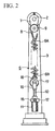
- FIG. 2 is a side view showing the essential parts of the foot pedal unit in the initial condition;
- FIG. 3 is a side view showing the essential parts of the foot pedal unit that are slightly moved in response to a player's operation for depressing a foot pedal;
- FIG. 4 is a front view showing the mechanical structure of a foot pedal unit that is conventionally used for a drum set; and
- FIG. 5 is an enlarged view partly in section showing essential parts around the adjustment screw in the foot pedal unit shown in FIG. 4.
-
- This invention will be described in further detail by way of examples with reference to the accompanying drawings.
- Figures 1 and 2 show essential parts of a foot pedal unit in accordance with one embodiment of the invention, wherein the parts identical to those shown in Figures 4 and 5 are designated by the same reference numerals; hence, the detailed description thereof will be omitted as necessary.
- In the present embodiment,
reference numeral 3 designates a support pole that is formed by the aluminum die cast. Similar to the aforementioned foot pedal unit shown in FIG. 4, there are provided a pair of the 'aluminum'support poles 3 on both sides of the foot pedal 4. Therotation shaft 2 is pivotally supported by the upper ends of thesupport poles 3. - The present embodiment is characterized by providing a brand-new automatic return structure at one end or each of both ends of the
rotation shaft 2. In the automatic return structure shown in Figures 1 and 2, acrank arm 7 is fixed to one end of therotation shaft 2, and aroller 9 is rotatably supported by the tip end of thecrank arm 7. Atension coil spring 6 is provided relative to thesupport pole 3 in order to apply a return characteristic to the foot pedal 4. Theupper end 6A of thetension coil spring 6 is hung on theroller 9 by means of alink member 8. - A
bracket 12 is formed as an integral part of thesupport pole 3 at its base portion. Anut 11 is attached to thebracket 12 in accordance with the foregoing structure shown in FIG. 5. Aholder 16 is attached to the tip end of anadjustment screw 10, so that aroller 17 is rotatably supported by theholder 16. Thelower end 6B of thetension coil spring 6 is hung on theroller 17 by means of alink member 18. - When the player plays the drum set equipped with the foot pedal unit of the present embodiment, the
rotation shaft 2 revolves every time the player depresses the foot pedal 4 with his/her foot, wherein thecrank arm 7 is correspondingly revolved so that its tip end automatically ascends up. Thus, theroller 9 attached to the tip end of thecrank arm 7 moves upwards to expand thetension coil spring 6 against its tension (or contraction) while guiding thelink member 8 outwardly from thesupport pole 3, which is shown in FIG. 3. - In FIG. 3, the
tension coil spring 6 is slightly inclined from its initial vertical position with respect to the fulcrum corresponding to theroller 17. Herein, the positional displacement is substantially absorbed by the revolution of theroller 17, which in turn avoids occurrence of contact friction with respect to thelower end 6B of thetension coil spring 6. - In summary, the present embodiment provides a completely novel foot pedal unit for use in the drum set, wherein even though a small positional displacement occurs at the lower end of the tension coil spring due to the player's operation of the foot pedal, it can be reliably absorbed by the revolution of the roller that is attached to the lower end of the tension coil spring. Therefore, it is possible to reliably avoid occurrence of unpleasant noise during the performance of the drum set equipped with the foot pedal unit. In addition, substantially no resistance is additionally applied to the player's operation of the pedal because of the 'smooth' revolution of the roller. Therefore, it is possible to provide noticeable effects for stabilizing the drum performance using the foot pedal.
- Incidentally, the present embodiment employs the
holder 16 androller 17 for avoiding unwanted friction and noise at the lower end of thetension coil spring 6. Of course, this invention is not necessarily limited to use theaforementioned elements - As this invention may be embodied in several forms without departing from the spirit or essential characteristics thereof, the present embodiment is therefore illustrative and not restrictive, since the scope of the invention is defined by the appended claims rather than by the description preceding them, and all changes that fall within metes and bounds of the claims, or equivalents of such metes and bounds are therefore intended to be embraced by the claims.
Claims (5)
- A foot pedal unit for a drum set comprising:wherein said automatic return structure comprisesa beater (1);a rotation shaft (2) to which the beater is attached at a prescribed position;a pair of support poles (3) whose upper ends rotatably support the rotation shaft;a foot pedal (4) whose tip end is interconnected to the rotation shaft by a transmission member (5); andan automatic return structure that automatically returns the beater and the foot pedal when a player depresses the foot pedal with his/her foot,
a tension coil spring (6) whose upper end (6A) is connected with a crank arm (7) that is attached to one end of the rotation shaft via a first roller (9),
an adjustment screw (10) that is fixed to a lower portion of the support pole and is manually adjusted in height, and
a second roller (17) by which a lower end (6B) of the tension coil spring is connected with the adjustment screw. - The foot pedal unit for a drum set according to claim 1, wherein the lower end of the tension coil spring is connected with the second roller that is held by a holder (16) attached to the adjustment screw.
- The foot pedal unit for a drum set according to claim 1, wherein the adjustment screw engages with a nut (11) that is fixed to a bracket (12), which is projected and formed as an integral part of the support pole.
- The foot pedal unit for a drum set according to claim 2, wherein the adjustment screw engages with a nut (11) that is fixed to a bracket (12), which is projected and formed as an integral part of the support pole.
- A foot pedal unit for a drum set comprising:wherein said automatic return structure comprisesa beater (1);a rotation shaft (2) to which the beater is attached;a pair of support poles (3) supporting the rotation shaft;a foot pedal (4) connected to the rotation shaft; andan automatic return structure that automatically returns the beater,
a tension coil spring (6) connected with the rotation shaft via a first roller (9);
an adjustment screw (10) that is fixed to a portion of the support pole, and
a second roller (17) by which the tension coil spring is connected with the adjustment screw.
Applications Claiming Priority (2)
| Application Number | Priority Date | Filing Date | Title |
|---|---|---|---|
| JP2001126161A JP3584898B2 (en) | 2001-04-24 | 2001-04-24 | Drum foot pedal device |
| JP2001126161 | 2001-04-24 |
Publications (2)
| Publication Number | Publication Date |
|---|---|
| EP1253580A1 true EP1253580A1 (en) | 2002-10-30 |
| EP1253580B1 EP1253580B1 (en) | 2006-07-12 |
Family
ID=18975245
Family Applications (1)
| Application Number | Title | Priority Date | Filing Date |
|---|---|---|---|
| EP02009167A Expired - Lifetime EP1253580B1 (en) | 2001-04-24 | 2002-04-24 | Foot pedal for drums |
Country Status (4)
| Country | Link |
|---|---|
| US (1) | US6713667B2 (en) |
| EP (1) | EP1253580B1 (en) |
| JP (1) | JP3584898B2 (en) |
| DE (1) | DE60213023T2 (en) |
Cited By (1)
| Publication number | Priority date | Publication date | Assignee | Title |
|---|---|---|---|---|
| CN107230467A (en) * | 2016-03-25 | 2017-10-03 | 雅马哈株式会社 | For bulging foot-treadle device |
Families Citing this family (6)
| Publication number | Priority date | Publication date | Assignee | Title |
|---|---|---|---|---|
| US7405352B2 (en) * | 2005-01-19 | 2008-07-29 | Trick Percussion Products, Inc. | Drum pedal |
| US7692084B1 (en) * | 2008-11-19 | 2010-04-06 | Mu-Sen Lai | Tension unit for a drum set pedal |
| US20120255423A1 (en) * | 2011-04-11 | 2012-10-11 | Geoff Saddler | Hi-hat support structure for drum set for use with a bass drum foot pedal |
| KR101364606B1 (en) * | 2012-07-06 | 2014-02-20 | (주)한국정밀 | Capo for guitar |
| JP6672677B2 (en) | 2015-09-30 | 2020-03-25 | ヤマハ株式会社 | Beater for drum and foot pedal device for drum |
| US11646003B1 (en) | 2020-10-01 | 2023-05-09 | Ronn Dunnett | Bass drum pedal compression mechanism |
Citations (1)
| Publication number | Priority date | Publication date | Assignee | Title |
|---|---|---|---|---|
| DE4020794A1 (en) * | 1989-07-11 | 1991-01-17 | Harald Bethke | Pedal actuated drumstick - has belt connection pedal to shaft carrying the drumstick which is connected to return spring |
Family Cites Families (2)
| Publication number | Priority date | Publication date | Assignee | Title |
|---|---|---|---|---|
| US3030847A (en) * | 1960-05-24 | 1962-04-24 | Joseph Rogers Inc | Drum beater |
| GB1538145A (en) * | 1976-08-27 | 1979-01-10 | Premier Drum Co Ltd | Bass drum pedal |
-
2001
- 2001-04-24 JP JP2001126161A patent/JP3584898B2/en not_active Expired - Fee Related
-
2002
- 2002-04-23 US US10/127,605 patent/US6713667B2/en not_active Expired - Lifetime
- 2002-04-24 EP EP02009167A patent/EP1253580B1/en not_active Expired - Lifetime
- 2002-04-24 DE DE60213023T patent/DE60213023T2/en not_active Expired - Lifetime
Patent Citations (1)
| Publication number | Priority date | Publication date | Assignee | Title |
|---|---|---|---|---|
| DE4020794A1 (en) * | 1989-07-11 | 1991-01-17 | Harald Bethke | Pedal actuated drumstick - has belt connection pedal to shaft carrying the drumstick which is connected to return spring |
Cited By (2)
| Publication number | Priority date | Publication date | Assignee | Title |
|---|---|---|---|---|
| CN107230467A (en) * | 2016-03-25 | 2017-10-03 | 雅马哈株式会社 | For bulging foot-treadle device |
| CN107230467B (en) * | 2016-03-25 | 2021-05-25 | 雅马哈株式会社 | Pedal device for drum |
Also Published As
| Publication number | Publication date |
|---|---|
| US6713667B2 (en) | 2004-03-30 |
| JP3584898B2 (en) | 2004-11-04 |
| JP2002323889A (en) | 2002-11-08 |
| DE60213023D1 (en) | 2006-08-24 |
| DE60213023T2 (en) | 2006-11-23 |
| US20020152873A1 (en) | 2002-10-24 |
| EP1253580B1 (en) | 2006-07-12 |
Similar Documents
| Publication | Publication Date | Title |
|---|---|---|
| US6590147B2 (en) | Bass drum pedal | |
| US6713667B2 (en) | Foot pedal for drums | |
| US7312389B2 (en) | Snare strainer | |
| JP5208999B2 (en) | Drum pedal bearing structure | |
| EP1424682A1 (en) | Keyboard instrument having pedal mechanism | |
| JP6672677B2 (en) | Beater for drum and foot pedal device for drum | |
| US10937400B1 (en) | Cable-driven beater mechanism for percussion instrument | |
| US6369308B1 (en) | Percussion instrument pedal assembly | |
| JP2738318B2 (en) | Drum foot pedal | |
| JP3173379B2 (en) | Drum foot pedal | |
| JP6610374B2 (en) | Foot pedal device for drum | |
| JP4253926B2 (en) | Musical instrument stand | |
| US5659144A (en) | Foot pedal for a drum | |
| CN113380212B (en) | Sound holding mechanism of keyboard musical instrument and keyboard musical instrument | |
| JP2019128372A (en) | Electronic bass drum | |
| WO1997022114A1 (en) | Bass drum pedal assembly | |
| JPH0895557A (en) | Foot pedal for drum | |
| CN113299254B (en) | Steel cable driving type wooden case drum hammer mechanism | |
| JP2574804Y2 (en) | timpani | |
| JP2806300B2 (en) | Drum foot pedal | |
| JP4083079B2 (en) | action | |
| JP2007286093A (en) | Balance shaft support mechanism | |
| JP3856007B2 (en) | Jack escapement adjusting device for keyboard instrument, silencer for keyboard instrument, and keyboard instrument | |
| JP2567764Y2 (en) | Electronic musical instrument keyboard device | |
| KR20040006843A (en) | Double Pedal for Bass Drum |
Legal Events
| Date | Code | Title | Description |
|---|---|---|---|
| PUAI | Public reference made under article 153(3) epc to a published international application that has entered the european phase |
Free format text: ORIGINAL CODE: 0009012 |
|
| AK | Designated contracting states |
Kind code of ref document: A1 Designated state(s): AT BE CH CY DE DK ES FI FR GB GR IE IT LI LU MC NL PT SE TR |
|
| AX | Request for extension of the european patent |
Free format text: AL;LT;LV;MK;RO;SI |
|
| 17P | Request for examination filed |
Effective date: 20030428 |
|
| AKX | Designation fees paid |
Designated state(s): DE GB |
|
| 17Q | First examination report despatched |
Effective date: 20041019 |
|
| GRAP | Despatch of communication of intention to grant a patent |
Free format text: ORIGINAL CODE: EPIDOSNIGR1 |
|
| GRAS | Grant fee paid |
Free format text: ORIGINAL CODE: EPIDOSNIGR3 |
|
| GRAA | (expected) grant |
Free format text: ORIGINAL CODE: 0009210 |
|
| AK | Designated contracting states |
Kind code of ref document: B1 Designated state(s): DE GB |
|
| REG | Reference to a national code |
Ref country code: GB Ref legal event code: FG4D |
|
| REF | Corresponds to: |
Ref document number: 60213023 Country of ref document: DE Date of ref document: 20060824 Kind code of ref document: P |
|
| PLBE | No opposition filed within time limit |
Free format text: ORIGINAL CODE: 0009261 |
|
| STAA | Information on the status of an ep patent application or granted ep patent |
Free format text: STATUS: NO OPPOSITION FILED WITHIN TIME LIMIT |
|
| 26N | No opposition filed |
Effective date: 20070413 |
|
| PGFP | Annual fee paid to national office [announced via postgrant information from national office to epo] |
Ref country code: GB Payment date: 20160420 Year of fee payment: 15 Ref country code: DE Payment date: 20160419 Year of fee payment: 15 |
|
| REG | Reference to a national code |
Ref country code: DE Ref legal event code: R119 Ref document number: 60213023 Country of ref document: DE |
|
| GBPC | Gb: european patent ceased through non-payment of renewal fee |
Effective date: 20170424 |
|
| PG25 | Lapsed in a contracting state [announced via postgrant information from national office to epo] |
Ref country code: DE Free format text: LAPSE BECAUSE OF NON-PAYMENT OF DUE FEES Effective date: 20171103 |
|
| PG25 | Lapsed in a contracting state [announced via postgrant information from national office to epo] |
Ref country code: GB Free format text: LAPSE BECAUSE OF NON-PAYMENT OF DUE FEES Effective date: 20170424 |