EP1253405B1 - Greifersystem umfassend ein Sensorsystem - Google Patents
Greifersystem umfassend ein Sensorsystem Download PDFInfo
- Publication number
- EP1253405B1 EP1253405B1 EP20020008459 EP02008459A EP1253405B1 EP 1253405 B1 EP1253405 B1 EP 1253405B1 EP 20020008459 EP20020008459 EP 20020008459 EP 02008459 A EP02008459 A EP 02008459A EP 1253405 B1 EP1253405 B1 EP 1253405B1
- Authority
- EP
- European Patent Office
- Prior art keywords
- interface
- unit
- remote
- remote control
- data
- Prior art date
- Legal status (The legal status is an assumption and is not a legal conclusion. Google has not performed a legal analysis and makes no representation as to the accuracy of the status listed.)
- Expired - Lifetime
Links
Images

Classifications
-
- B—PERFORMING OPERATIONS; TRANSPORTING
- B25—HAND TOOLS; PORTABLE POWER-DRIVEN TOOLS; MANIPULATORS
- B25J—MANIPULATORS; CHAMBERS PROVIDED WITH MANIPULATION DEVICES
- B25J9/00—Program-controlled manipulators
- B25J9/16—Program controls
- B25J9/1612—Program controls characterised by the hand, wrist, grip control
-
- G—PHYSICS
- G01—MEASURING; TESTING
- G01D—MEASURING NOT SPECIALLY ADAPTED FOR A SPECIFIC VARIABLE; ARRANGEMENTS FOR MEASURING TWO OR MORE VARIABLES NOT COVERED IN A SINGLE OTHER SUBCLASS; TARIFF METERING APPARATUS; MEASURING OR TESTING NOT OTHERWISE PROVIDED FOR
- G01D5/00—Mechanical means for transferring the output of a sensing member; Means for converting the output of a sensing member to another variable where the form or nature of the sensing member does not constrain the means for converting; Transducers not specially adapted for a specific variable
- G01D5/26—Mechanical means for transferring the output of a sensing member; Means for converting the output of a sensing member to another variable where the form or nature of the sensing member does not constrain the means for converting; Transducers not specially adapted for a specific variable characterised by optical transfer means, i.e. using infrared, visible, or ultraviolet light
- G01D5/39—Scanning a visible indication of the measured value and reproducing this indication at the remote place, e.g. on the screen of a cathode ray tube
Definitions
- the invention relates to a gripper system comprising a gripping device, a sensor system and a data transmission connection from the sensor system to a remote interrogation and remote control unit.
- the sensor system has a position measuring sensor, which can be arranged, in particular, on a gripping device and an evaluation electronic unit connected to the measuring sensor, wherein the electronic evaluation unit has a first interface to the measuring sensor, a second interface to a machine control and means for programming the electronic evaluation unit.
- the evaluation electronic unit evaluates the data acquired by the measuring sensor and forwards them to a machine controller via the second interface.
- the machine control controls u.a. on the basis of the data transmitted by the evaluation electronics unit to the machine controller, the gripping device. This is a closed control circuit.
- the gripper jaws are moved to predetermined positions.
- a predetermined position is stored in the teaching method via corresponding means of the evaluation electronic unit.
- such a programmed or stored position of the gripper jaws are queried via the machine control.
- multiple positions can be programmed in the manner described.
- the connection line between the position sensors and the evaluation electronics unit can not be of any desired length. In practice, the maximum length is about 1 to 1.5 m. Since the position sensors must be arranged directly on the gripping device, wherein the gripping device in turn is regularly arranged on a handling device or on a robot arm, means for amplifying the measuring signals can not or only be provided with a very high effort. Due to the relatively small distance between the evaluation electronics unit and the gripping device, the programming of the evaluation electronics unit can be very cumbersome, particularly in the case of inaccessible gripping devices.
- a machine control is connected to sensor systems and controls control valves as a function of the measured values of the sensor systems.
- the machine control can be queried remotely via a transmission line. Remote intervention in the machine control can result in undesired changes or manipulations of the operating software.
- document DE3612144 discloses a gripper system comprising a gripping device, a sensor system and a data transmission connection from the sensor system to a remote interrogation and remote control unit, wherein the sensor system comprises a positionable on the gripping device position sensor and connected to the position sensor, the position sensor detected by the data evaluating evaluation electronics unit, wherein the evaluation electronics unit a first interface to the position sensor and a second interface for supplying the evaluated data to a machine controller and for querying the programmed set positions by the machine control.
- the present invention has the object to remedy the disadvantages of the known prior art.
- a control of the evaluation electronics unit is to be made possible even in inaccessible evaluation electronic units.
- This gripper system has the advantage that the data captured by the sensor system can be queried remotely.
- the evaluation electronics unit can be remotely accessed, so that likewise the programming of the evaluation electronics unit can not be carried out locally, but remotely.
- two third interfaces are present at the evaluation electronics unit, wherein the one third interface is a separately formed interface and the other third interface is designed as part of the second interface.
- the one remote interrogation and remote control unit is advantageously via the present in the second interface third interface continuously via the data transmission connection to the evaluation electronics unit connectable. If required, the other remote interrogation and remote control unit can be locally connected to the evaluation electronics unit for on-site diagnosis via the separately formed third interface. Such a need may be present, for example, in the event of failure or failure of the evaluation electronics unit.
- the third interface of the evaluation electronic unit is designed as a socket and / or plug unit.
- Such interfaces have the advantage that they build very small and a ensure reliable contact.
- the interfaces can also be protected in a simple manner against environmental influences.
- the third interface can be designed for example as an extra power strip.
- the other third interface of the evaluation electronics unit is designed as part of the second interface leading to the machine control.
- the second interface is designed as a multi-pin plug connection to the machine control.
- the interface formed as part of the second interface can be connected to the remote interrogation and control unit via a telecommunication connection, which can be analog and / or digital.
- a telecommunication connection which can be analog and / or digital.
- Sensor system for example, via an intranet or over the Internet remotely queried and remotely controlled.
- downtimes can be shortened, in particular in the event of an outage or malfunction of the sensor system. It also eliminates travel expenses for service and repair professionals.
- the evaluation electronic unit records its operating state when predetermined limit values are exceeded.
- Limit values may in this case be, in particular, a critical temperature or a critical operating voltage value.
- a memory unit is provided within the evaluation electronics unit. This can be achieved that a diagnosis of errors occurring due to the records is made possible.
- the gripper system according to the invention has the particular advantage that the closed control or regulating circuit can be remotely interrogated and remotely controlled via a remote interrogation and remote control unit, which can be connected to the evaluation electronics unit via its third interface.
- the evaluation electronics unit can be connected to the remote control unit via the machine controller with relatively little additional effort Remote control unit to be connected.
- the data transfer connection is made by the machine controller via the other third interface, without the machine controller processing the transmitted data to control the gripping device.
- the machine control here serves only as a connecting element between the evaluation electronic unit and the remote sensing and remote control unit. This has the particular advantage that in the case of a remote inquiry and remote control of the evaluation electronic unit there is no danger that a change or reprogramming of the machine control can take place. This ensures that the machine control can not be manipulated by the remote inquiry and remote control.
- a further, advantageous embodiment of the invention is characterized in that the evaluation electronics unit and / or the remote sensing and remote control unit records the operating state of the evaluation electronics unit when predetermined limit values are exceeded. This optimizes the fault diagnosis if the evaluation electronics unit fails.
- the output signals of the position sensors are supplied in V or A respectively.
- the acquired measured values are converted and displayed by the remote inquiry and remote control unit into user-friendly units of length, in particular in the mm stroke of the gripper jaws.
- Predefined positions of the gripping device or its gripper jaws can also be programmed via the remote interrogation and remote control unit without having to use the teaching method.
- the desired positions of the gripper jaws of the gripping device to be approached are programmed in known length units, in particular in mm, via the remote interrogation and remote control unit.
- evaluation electronics unit 10 shown comprises a housing 12 which has on its upper side 14 different operating buttons for programming the evaluation electronics unit 10.
- the upper side 14 can be covered by means of a covering element 16, which is arranged pivotably on the housing 12.
- the evaluation electronics unit 10 has a first interface 18 for connection to a, in particular a gripper device can be arranged in FIG. 3 shown, sensor on. Furthermore, the evaluation electronics unit 10 provides a second interface 20 to a machine control.
- the evaluation electronics unit 10 has two third interfaces 22 and 24.
- the third interface 22 is arranged as a separately formed interface in the form of a connector strip on the coverable top 14 of the housing 12.
- the further third interface 24 is designed as part of the second interface 20.
- the second interface 20 is designed as a plug-in unit, which has a plurality of in Fig. 2 having shown pins. In the embodiment illustrated in the figures, two pins of the plug unit of the interface 20 form the further third interface 24.
- the two third interfaces 22 and 24 can be connected via separate data transmission connections to a remote interrogation and remote control unit.
- the interface 22 is used only in case of need on site.
- the interface 24 is advantageously connected together with the interface 20 via a common cable harness with a machine control.
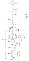
- FIG. 3 is the evaluation electronics unit 10 according to FIGS. 1 and 2 represented as a part of a gripper system.
- the gripper system comprises a gripping device 30 with two movable fingers 32. The fingers are arranged on the gripping device displaceable or pivotally mounted base jaws.
- a measuring sensor 34 in particular a position measuring sensor is arranged, which is connected via an electrical line 36 to the interface 18 of the Ausreteelektronikü 10. Via the line 36, only data in the direction of the measuring sensor 34 to the evaluation electronics unit 10 are transmitted.
- the measuring sensor 34, the line 36 and the evaluation electronics unit 10 form a sensor system.
- the gripper system further comprises a machine controller 38, which is connected via the interface 20 and an electrical line 40 to the evaluation electronics unit 10. Via the line 40, the data acquired by the evaluation electronics unit 10 of the measuring sensor 34 of the machine controller 38 are supplied. The data is processed within the machine controller 38. On the basis of the processed data, the machine controller 38 controls the drive (not shown) of the gripping device 30 via the control line 42.
- the measuring device 34, the line 36, the evaluation electronics unit 10, the line 40, the machine control 38 and the line 42 thus form a closed control circuit.
- Gripper system shown also has a remote sensing and remote control unit in the form of a computer unit 44.
- the computer unit 44 is connected via a data transmission connection 46 to the interface 24 of the evaluation electronics unit 10.
- the communication link 46 is composed of various sections.
- the first section 48 connects directly to the interface 24 and connects the evaluation electronics unit 10 with the machine control 38.
- a subsequent to the first section 48 further section 50 extends within the machine control 38.
- This section 50 is followed by a Telecommunications connection 52 which leads to the computer unit 44.
- the telecommunication connection 52 may in this case have any length.
- upstream and downstream electronic components 54 such as modulators, converters or amplifiers, are to be provided in the telecommunication connection 52 or the telecommunication connection 52.
- connection section 52 only passes through the machine control 38. This has the advantage that manipulation of the machine control 38 by the computer unit 44 is precluded. Consequently, the computer unit 44 can only use the evaluation electronics unit 10 for remote inquiry and remote control and not - at least not directly - the machine controller 38. Via the data transmission connection 46, data can be transmitted in both directions.
- FIG. 3 It will also be apparent that the two leads 48 and 40 are fed within a common harness 56 to the machine controller 38.
- the evaluation electronics unit 10 can be programmed, monitored and controlled. For example, several starting positions of the fingers 32 of the gripping device 30 can be programmed via the computer unit 44. Remote maintenance and remote diagnosis of the evaluation electronics unit 10 can likewise be undertaken via the computer unit 44. In addition, a process monitoring of the gripping operation of the gripping device 30 take place, which in particular allows to analyze occurring errors.
- the evaluation electronics unit 10 sends a preventive error message to the computer unit 44 when certain limit values are exceeded.
- limits may be, for example, critical temperatures or critical operating voltages.
- the computer unit 44 may also include oscilloscope functions that can quickly detect any disturbances that occur.
- query and / or control values in a unit of length, in particular in mm can be interrogated and input via the computer unit 44.
- a further remote sensing and remote control unit in the form of another computer 58 with the Evaluation electronics unit 10 are connected via an electrical line 60.
- the computer unit 58 includes the same functions as the computer unit 44. In particular, all essential query and control values can be queried and entered with the computer unit 58 and the evaluation electronics unit 10 can be monitored and programmed.
Landscapes
- Engineering & Computer Science (AREA)
- Health & Medical Sciences (AREA)
- General Health & Medical Sciences (AREA)
- Orthopedic Medicine & Surgery (AREA)
- Robotics (AREA)
- Mechanical Engineering (AREA)
- Physics & Mathematics (AREA)
- General Physics & Mathematics (AREA)
- Arrangements For Transmission Of Measured Signals (AREA)
- Selective Calling Equipment (AREA)
- Manipulator (AREA)
Description
- Die Erfindung betrifft ein Greifersystem umfassend eine Greifvorrichtung, ein Sensorsystem und eine Datenübertragungsverbindung vom Sensorsystem zu einer Fernabfrage- und Fernsteuerungseinheit. Das Sensorsystem weist einen insbesondere an einer Greifvorrichtung anordenbaren Positionsmesssensor und eine mit dem Messsensor verbundene Auswerteelektronikeinheit auf, wobei die Auswerteelektronikeinheit eine erste Schnittstelle zu dem Messsensor, eine zweite Schnittstelle zu einer Maschinensteuerung und Mittel zum Programmieren der Auswerteelektronikeinheit aufweist. Über ein derartiges Sensorsystem kann insbesondere die Hubposition von verfahrbaren Greiferbacken einer Greifvorrichtung erfasst werden. Die Auswerteelektronikeinheit wertet die von dem Messsensor erfassten Daten aus und leitet sie über die zweite Schnittstelle einer Maschinensteuerung zu. Die Maschinensteuerung steuert u.a. aufgrund der von der Auswerteelektronikeinheit an die Maschinensteuerung übermittelten Daten die Greifvorrichtung. Damit liegt ein geschlossener Steuerkreis vor.
- Zum Programmieren der Auswerteelektronikeinheit werden die Greiferbacken in vorgegebene Positionen verfahren. Eine vorgegebene Position wird im Teaching-Verfahren über entsprechende Mittel der Auswerteelektronikeinheit gespeichert. Zu einem späteren Zeitpunkt kann eine derart programmierte bzw. gespeicherte Position der Greiferbacken über die Maschinensteuerung abgefragt werden. Vorteilhafterweise können mehrere Positionen auf die beschriebene Art und Weise programmiert werden.
- Derart bekannte Sensorsysteme werden von der Firma Schunk GmbH & Co. KG, 74348 Lauffen/Neckar vertrieben und sind aus Zubehörkatalogen (Schunk GmbH & Co. KG, Katalog: Zubehör Greifersysteme, 02/2001, Auswerteelektronikeinheit FPS mit Messsensoren) bekannt.
- Aufgrund der relativ schwachen Messsignale der an der Greifvorrichtung angeordneten Positionssensoren, die über eine elektrische Leitung mit der Auswerteelektronikeinheit verbunden sind, kann die Verbindungsleitung zwischen den Positionssensoren und der Auswerteelektronikeinheit nicht beliebig lang sein. In der Praxis beträgt die maximale Länge ca. 1 bis 1,5 m. Da die Positionssensoren unmittelbar an der Greifvorrichtung angeordnet sein müssen, wobei die Greifvorrichtung ihrerseits regelmäßig an einem Handhabungsgerät bzw. an einem Roboterarm angeordnet ist, können Mittel zur Verstärkung der Messsignale nicht bzw. nur mit einem sehr hohen Aufwand vorgesehen werden. Aufgrund des relativ geringen Abstands der Auswerteelektronikeinheit zu der Greifvorrichtung kann sich die Programmierung der Auswerteelektronikeinheit insbesondere bei unzugänglichen Greifvorrichtungen sehr mühsam gestalten.
- Ein weiterer Nachteil des bekannten Standes der Technik ist, dass eine Kontrolle der Auswerteelektronikeinheit, insbesondere bei Ausfall der Auswerteelektronikeinheit nur vor Ort möglich ist. Insbesondere bei unzugänglich angeordneten Greifvorrichtungen bzw. Auswerteelektronikeinheiten führt dies zu relativ langen Stillstandzeiten der Greifvorrichtung.
- Aus der
WO01/1666 - Dokument
DE3612144 offenbart ein Greifersystem umfassend eine Greifvorrichtung, ein Sensorsystem und eine Datenübertragungsverbindung vom Sensorsystem zu einer Fernabfrage- und Fernsteuerungseinheit, wobei das Sensorsystem einen an der Greifvorrichtung anordenbaren Positionssensor und eine mit dem Positionssensor verbundene, die vom Positionssensor erfassten Daten auswertende Auswerteelektronikeinheit aufweist, wobei die Auswerteelektronikeinheit eine erste Schnittstelle zu dem Positionssensor und eine zweite Schnittstelle zur Zuleitung der ausgewerteten Daten zu einer Maschinensteuerung und zum Abfragen der programmierten Sollpositionen durch die Maschinensteuerung aufweist. - Der vorliegenden Erfindung liegt die Aufgabe zugrunde, den Nachteilen des bekannten Standes der Technik abzuhelfen. Insbesondere soll eine Kontrolle der Auswerteelektronikeinheit auch bei unzugänglich angeordneten Auswerteelektronikeinheiten ermöglicht werden.
- Diese Aufgabe wird bei einem Greifersystem mit den Merkmalen des Anspruchs 1 gelöst.
- Dieses Greifersystem hat den Vorteil, dass die von dem Sensorsystem erfassten Daten fern abgefragt werden können.
- Außerdem kann auf die Auswerteelektronikeinheit ferngesteuert zugegriffen werden, so dass ebenfalls die Programmierung der Auswerteelektronikeinheit nicht vor Ort, sondern von der Ferne durchgeführt werden kann. Dabei sind an der Auswerteelektronikeinheit zwei dritte Schnittstellen vorhanden, wobei die eine dritte Schnittstelle eine separat ausgebildete Schnittstelle und die andere dritte Schnittstelle als Teil der zweiten Schnittstelle ausgebildet ist. Dies hat den Vorteil, dass zwei unabhängige Fernabfrage- und Steuerungseinheiten über Datenübertragungsverbindungen mit der Auswerteelektronikeinheit verbindbar sind. Die eine Fernabfrage- und Fernsteuerungseinheit ist vorteilhafterweise über die in der zweiten Schnittstelle vorhandene dritte Schnittstelle fortwährend über die Datenübertragungsverbindung mit der Auswerteelektronikeinheit verbindbar. Die andere Fernabfrage- und Fernsteuerungseinheit kann im Bedarfsfall vor Ort über die separat ausgebildete dritte Schnittstelle mit der Auswerteelektronikeinheit zur Vor-Ort-Diagnose verbunden werden. Ein derartiger Bedarf kann beispielsweise bei Ausfall oder Störung der Auswerteelektronikeinheit vorliegen.
- Vorteilhafterweise ist die eine dritte Schnittstelle der Auswerteelektronikeinheit als Buchsen- und/oder Steckereinheit ausgebildet. Derartige Schnittstellen haben den Vorteil, dass sie sehr klein bauen und eine funktionssichere Kontaktierung gewährleisten. Die Schnittstellen sind ebenfalls auf einfache Art und weise gegen Umwelteinflüsse schützbar. Die eine dritte Schnittstelle kann beispielsweise als extra Steckerleiste ausgeführt sein.
- Erfindungsgemäß ist vorgesehen, dass die andere dritte Schnittstelle der Auswerteelektronikeinheit als Teil der zweiten, zu der Maschinensteuerung führenden Schnittstelle ausgebildet ist. Dies hat den Vorteil, dass keine separate, zusätzliche Schnittstelle erforderlich ist. Regelmäßig ist die zweite Schnittstelle als mehrpolige Steckerverbindung zu der Maschinensteuerung ausgeführt. Vorteilhafterweise werden mindestens zwei Pole bzw. Pins der zweiten Schnittstelle zur Verbindung der Fernabfrage- und Fernsteuerungseinheit als dritte Schnittstelle - innerhalb der zweiten Schnittstelle - ausgebildet. Dies hat den Vorteil, dass ein zusätzlicher Kabelstrang zu der Auswerteelektronikeinheit nicht erforderlich ist. Das äußere Erscheinungsbild der bekannten Auswerteelektronikeinheit verändert sich hierdurch nicht.
- Bei einer weiteren Ausführungsform der Erfindung ist vorgesehen, dass die als Teil der zweiten Schnittstelle ausgebildete Schnittstelle über eine Telekommunikationsverbindung, die analog und/oder digital ausgeführt sein kann, mit der Fernabfrage- und Steuerungseinheit verbindbar ist. Damit kann das Sensorsystem beispielsweise über ein Intranet oder über das Internet fernabgefragt und ferngesteuert werden. Hierdurch können insbesondere bei einem Aus- oder Störfall des Sensorsystems Stillstandzeiten verkürzt werden. Außerdem entfallen Reisekosten für Service- und Reparaturfachkräfte.
- Bei einer anderen Ausführungsform der Erfindung ist vorgesehen, dass die Auswerteelektronikeinheit bei Überschreiten von vorgegebenen Grenzwerten ihren Betriebszustand aufzeichnet. Grenzwerte können hierbei insbesondere eine kritische Temperatur oder eine kritischer Betriebsspannungswert sein. Zur Aufzeichnung ist eine Speichereinheit innerhalb der Auswerteelektronikeinheit vorgesehen. Hierdurch kann erreicht werden, dass eine Diagnose bei auftretenden Fehlern aufgrund der Aufzeichnungen ermöglicht wird.
- Das erfindungsgemäße Greifersystem hat insbesondere den Vorteil, dass der geschlossene Steuer- bzw. Regelkreis über eine Fernabfrage- und Fernsteuerungseinheit, die mit der Auswerteelektronikeinheit über deren dritte Schnittstelle verbindbar ist, fernabfragbar und fernsteuerbar ist.
- Da an sich über die zweite Schnittstelle der Auswerteelektronikeinheit eine Verbindung zu der Maschinensteuerung vorgesehen ist, kann mit relativ wenig zusätzlichem Aufwand die Auswerteelektronikeinheit über die Maschinensteuerung mit der Fernabfrage- und Fernsteuereinheit verbunden werden.
- Über die andere dritte Schnittstelle erfolgt die Datenübertragungsverbindung durch die Maschinensteuerung, ohne dass die Maschinensteuerung die übertragenen Daten zur Steuerung der Greifvorrichtung verarbeitet. Die Maschinensteuerung dient hierbei lediglich als verbindendes Element zwischen der Auswerteelektronikeinheit und der Fernabfrage- und Fernsteuerungseinheit. Dies hat insbesondere den Vorteil, dass bei einer Fernabfrage und Fernsteuerung der Auswerteelektronikeinheit keine Gefahr besteht, dass eine Veränderung bzw. Umprogrammierung der Maschinensteuerung erfolgen kann. Hierdurch wird gewährleistet, dass die Maschinensteuerung durch die Fernabfrage und Fernsteuerung nicht manipuliert werden kann.
- Eine weitere, vorteilhafte Ausgestaltung der Erfindung zeichnet sich dadurch aus, dass die Auswerteelektronikeinheit und/oder die Fernabfrage- und Fernsteuerungseinheit bei Überschreiten von vorgegebenen Grenzwerten den Betriebszustand der Auswerteelektronikeinheit aufzeichnet. Hierdurch wird die Fehlerdiagnose bei Ausfall der Auswerteelektronikeinheit optimiert.
- Weiterhin kann erfindungsgemäß vorgesehen sein, dass über die Fernabfrage- und Fernsteuerungseinheit Abfrage- und/oder Steuerungswerte in einer Längeneinheit abfragbar bzw. eingebbar sind. Grundsätzlich werden die Ausgangssignale der Positionssensoren in V bzw. A geliefert. Nach einer einmalig vorzunehmenden Kalibrierung des Systems werden die erfassten Messwerte von der Fernabfrage- und Fernsteuerungseinheit in benutzerfreundliche Längeneinheiten, insbesondere in mm-Hubweg der Greiferbacken umgerechnet und angezeigt. Hierdurch wird die Benutzerfreundlichkeit des Greifersystems erheblich verbessert.
- Über die Fernabfrage- und Fernsteuerungseinheit können auch vorgegebene Positionen der Greifvorrichtung bzw. deren Greiferbacken programmiert werden, ohne das Teaching-Verfahren anwenden zu müssen. Vorteilhafterweise werden die anzufahrenden Sollpositionen der Greiferbacken der Greifvorrichtung in bekannten Längeneinheiten, insbesondere in mm, über die Fernabfrage- und Fernsteuerungseinheit programmiert.
- Weitere vorteilhafte Ausgestaltungen und Einzelheiten der Erfindung sind der folgenden Beschreibung zu entnehmen, in der die Erfindung anhand des in der Zeichnung dargestellten Ausführungsbeispiels näher beschrieben und erläutert ist.
- Es zeigen:
- Figur 1
- und
Figur 2 die Auswerteelektronikeinheit eines Sensorsystems in verschiedenen perspektivischen Ansichten; und
Figur 3 eine schematische Darstellung eines Greifersystems. - Die in
Figur 1 dargestellte Auswerteelektronikeinheit 10 weist ein Gehäuse 12 auf, das an seiner Oberseite 14 verschiedene Betätigungstasten zur Programmierung der Auswerteelektronikeinheit 10 aufweist. Die Oberseite 14 ist mittels eines an dem Gehäuse 12 schwenkbar angeordneten Abdeckelements 16 abdeckbar. - Die Auswerteelektronikeinheit 10 weist eine erste Schnittstelle 18 zur Verbindung mit einem an insbesondere einer Greifervorrichtung anordenbaren, in
Figur 3 dargestellten, Sensor auf. Ferner sieht die Auswerteelektronikeinheit 10 eine zweite Schnittstelle 20 zu einer Maschinensteuerung vor. - Erfindungsgemäß weist die Auswerteelektronikeinheit 10 zwei dritte Schnittstellen 22 und 24 auf. Die dritte Schnittstelle 22 ist als separat ausgebildete Schnittstelle in Form einer Steckerleiste an der abdeckbaren Oberseite 14 des Gehäuses 12 angeordnet. Die weitere dritte Schnittstelle 24 ist als Teil der zweiten Schnittstelle 20 ausgebildet. Die zweite Schnittstelle 20 ist als Steckereinheit ausgeführt, die eine Vielzahl von in
Fig. 2 dargestellten Pins aufweist. Bei der in den Figuren dargestellten Ausführungsform bilden zwei Pins der Steckereinheit der Schnittstelle 20 die weitere dritte Schnittstelle 24. - Die beiden dritten Schnittstellen 22 und 24 sind über jeweils getrennte Datenübertragungsverbindungen mit einer Fernabfrage- und Fernsteuerungseinheit verbindbar. Vorteilhafterweise wird die Schnittstelle 22 lediglich im Bedarfsfalle vor Ort verwendet. Die Schnittstelle 24 ist vorteilhafterweise zusammen mit der Schnittstelle 20 über einen gemeinsamen Kabelstrang mit einer Maschinensteuerung verbindbar.
- In
Figur 3 ist die Auswerteelektronikeinheit 10 gemäßFigur 1 und 2 als ein Teil eines Greifersystems dargestellt. Das Greifersystem umfasst eine Greifvorrichtung 30 mit zwei verfahrbaren Fingern 32. Die Finger sind an der Greifvorrichtung verschieblich oder verschwenkbar gelagerten Grundbacken angeordnet. An der Greifvorrichtung 30 ist ein Messsensor 34, insbesondere ein Positionsmesssensor angeordnet, der über eine elektrische Leitung 36 mit der Schnittstelle 18 der Auswerteelektronikeinheit 10 verbunden ist. Über die Leitung 36 werden lediglich Daten in Richtung von dem Messsensor 34 zu der Auswerteelektronikeinheit 10 übertragen. Der Messsensor 34, die Leitung 36 und die Auswerteelektronikeinheit 10 bilden ein Sensorsystem. - Das Greifersystem umfasst ferner eine Maschinensteuerung 38, die über die Schnittstelle 20 und eine elektrische Leitung 40 mit der Auswerteelektronikeinheit 10 verbunden ist. Über die Leitung 40 werden die von der Auswerteelektronikeinheit 10 erfassten Daten des Messsensors 34 der Maschinensteuerung 38 zugeführt. Die Daten werden innerhalb der Maschinensteuerung 38 verarbeitet. Aufgrund der verarbeiteten Daten steuert die Maschinensteuerung 38 über die Steuerleitung 42 den nicht dargestellten Antrieb der Greifvorrichtung 30. Die Messvorrichtung 34, die Leitung 36, die Auswerteelektronikeinheit 10, die Leitung 40, die Maschinensteuerung 38 sowie die Leitung 42 bilden demnach einen geschlossenen Steuerkreis.
- Das in
Figur 3 gezeigte Greifersystem weist außerdem eine Fernabfrage- und Fernsteuerungseinheit in Form einer Computereinheit 44 auf. Die Computereinheit 44 ist über eine Datenübertragungsverbindung 46 mit der Schnittstelle 24 der Auswerteelektronikeinheit 10 verbunden. Die Datenübertragungsverbindung 46 setzt sich aus verschiedenen Abschnitten zusammen. Der erste Abschnitt 48 schließt sich unmittelbar an die Schnittstelle 24 an und verbindet die Auswerteelektronikeinheit 10 mit der Maschinensteuerung 38. Ein sich an den ersten Abschnitt 48 anschließender weiterer Abschnitt 50 verläuft innerhalb der Maschinensteuerung 38. An diesen Abschnitt 50 schließt sich eine Telekommunikationsverbindung 52 an, die zu der Computereinheit 44 führt. Die Telekommunikationsverbindung 52 kann hierbei eine beliebige Länge aufweisen. Je nach Art der Telekommunikationsverbindung 52 (digital/analog) sind in der Telekommunikationsverbindung 52 bzw. der Telekommunikationsverbindung 52 vor- und nachgeschaltete elektronische Bauteile 54, wie beispielsweise Modulierer, Wandler oder Verstärker vorzusehen. - Wie aus
Figur 3 deutlich wird, wird von der Maschinensteuerung 38 vorzugsweise nicht auf den Verbindungsabschnitt 52 zur Steuerung der Greifvorrichtung 30 zurückgegriffen. Der Verbindungsabschnitt 52 durchquert lediglich die Maschinensteuerung 38. Dies hat den Vorteil, dass eine Manipulation der Maschinensteuerung 38 durch die Computereinheit 44 ausgeschlossen ist. Mit der Computereinheit 44 kann folglich lediglich auf die Auswerteelektronikeinheit 10 zur Fernabfrage und Fernsteuerung zurückgegriffen werden und nicht - zumindest nicht unmittelbar - auf die Maschinensteuerung 38. Über die Datenübertragungsverbindung 46 können Daten in beide Richtungen übertragen werden. - Aus
Figur 3 wird ebenfalls deutlich, dass die beiden Leitungen 48 und 40 innerhalb eines gemeinsamen Kabelstranges 56 der Maschinensteuerung 38 zugeführt werden. - Über die Computereinheit 44 kann die Auswerteelektronikeinheit 10 programmiert, überwacht und gesteuert werden. Beispielsweise können mehrere Anfahrpositionen der Finger 32 der Greifvorrichtung 30 über die Computereinheit 44 programmiert werden. Über die Computereinheit 44 kann ebenfalls eine Fernwartung und Ferndiagnose der Auswerteelektronikeinheit 10 vorgenommen werden. Außerdem kann eine Prozessüberwachung des Greifvorganges der Greifvorrichtung 30 erfolgen, die es insbesondere erlaubt, auftretende Fehler zu analysieren.
- Ferner kann erfindungsgemäß vorgesehen sein, dass die Auswerteelektronikeinheit 10 bei Überschreiten von bestimmten Grenzwerten eine präventive Fehlermeldung an die Computereinheit 44 abgibt. Derartige Grenzwerte können beispielsweise kritische Temperaturen oder kritische Betriebsspannungen sein.
- Die Computereinheit 44 kann außerdem Oszilloskop-Funktionen beinhalten, mit welchen auftretende Störungen schnell erkannt werden können. Vorteilhafterweise können über die Computereinheit 44 Abfrage- und/oder Steuerungswerte in einer Längeneinheit, insbesondere in mm, abgefragt und eingegeben werden.
- Über die Schnittstelle 22 kann im Bedarfsfall temporär eine weitere Fernabfrage- und Fernsteuerungseinheit in Form eines weiteren Computers 58 mit der Auswerteelektronikeinheit 10 über eine elektrische Leitung 60 verbunden werden. Die Computereinheit 58 beinhaltet die gleichen Funktionen wie die Computereinheit 44. Insbesondere können alle wesentlichen Abfrage- und Steuerungswerte mit der Computereinheit 58 abgefragt und eingegeben werden sowie die Auswerteelektronikeinheit 10 überwacht und programmiert werden.
Claims (5)
- Greifersystem umfassend eine Greifvorrichtung (30), ein Sensorsystem und eine Datenübertragungsverbindung (46, 60) vom Sensorsystem zu einer Fernabfrage- und Fernsteuerungseinheit (44, 58),
wobei das Sensorsystem einen an der Greifvorrichtung (30) anordenbaren Positionssensor (34) und eine mit dem Positionssensor (34) verbundene, die vom Positionssensor erfassten Daten auswertende Auswerteelektronikeinheit (10) aufweist,
wobei die Auswerteelektronikeinheit (10) aufweist:- Mittel eingerichtet zum Programmieren der Auswerteelektronikeinheit (10) mit anzufahrenden Sollpositionen von Greiferbacken der Greifvorrichtung,- eine erste Schnittstelle (18) zu dem Positionssensor (34),- eine zweite Schnittstelle (20) zur Zuleitung der ausgewerteten Daten zu einer Maschinensteuerung (38) und zum Abfragen der programmierten Sollpositionen durch die Maschinensteuerung (38) und- zwei dritte Schnittstellen (22, 24) für die Datenübertragungsverbindung (46, 60) zur Fernabfrage- und Fernsteuerungseinheit (44, 58),wobei die eine dritte Schnittstelle (22) eine separate ausgebildete Schnittstelle und die andere dritte Schnittstelle (24) als Teil der zweiten Schnittstelle (20) ausgebildet ist,
wobei über die dritten Schnittstellen (22, 24) zum einen die vom Positionssensor (34) erfassten Daten fern abgefragt und zum anderen auf die Auswerteelektronikeinheit (10) ferngesteuert derart zugegriffen werden kann, dass die Programmierung der Auswerteelektronikeinheit (10) von der Ferne durchgeführt werden kann,
wobei die Datenübertragungsverbindung (46) über die andere dritte Schnittstelle (24) durch die Maschinensteuerung (38) so erfolgt, dass die Maschinensteuerung (38) die übertragenen Daten zur Steuerung der Greifvorrichtung (30) derart verarbeitet, dass keine Veränderung bzw. Umprogrammierung der Maschinensteuerung (38) durch die Fernabfrage und Fernsteuerung erfolgen kann. - Greifersystem nach Anspruch 1, dadurch gekennzeichnet, dass die dritte Schnittstelle der Auswerteelektronikeinheit (10) als Buchsen- und/oder Steckereinheit ausgebildet ist.
- Greifersystem nach einem der vorhergehenden Ansprüche, dadurch gekennzeichnet, dass die als Teil der zweiten Schnittstelle (20) ausgebildete dritte Schnittstelle (24) der Auswerteelektronikeinheit (10) über eine Telekommunikationsverbindung (46) mit der Fernabfrage- und Fernsteuerungseinheit (44, 58) verbindbar ist.
- Greifersystem nach einem der vorhergehenden Ansprüche, dadurch gekennzeichnet, dass die Auswerteelektronikeinheit (10) und/oder die Fernabfrage- und Fernsteuerungseinheit (44, 58) bei Überschreiten von vorgegebenen Grenzwerten den Betriebszustand der Auswerteelektronikeinheit (10) aufzeichnet.
- Greifersystem nach einem der vorhergehenden Ansprüche, dadurch gekennzeichnet, dass über die Fernabfrage- und Fernsteuerungseinheit (44, 58) Abfrage- und/oder Steuerungswerte in einer Längeneinheit abfragbar bzw. eingebbar sind.
Applications Claiming Priority (2)
| Application Number | Priority Date | Filing Date | Title |
|---|---|---|---|
| DE10120948 | 2001-04-23 | ||
| DE2001120948 DE10120948C1 (de) | 2001-04-23 | 2001-04-23 | Sensorsystem für ein Greifersystem sowie Greifersystem |
Publications (2)
| Publication Number | Publication Date |
|---|---|
| EP1253405A1 EP1253405A1 (de) | 2002-10-30 |
| EP1253405B1 true EP1253405B1 (de) | 2013-10-09 |
Family
ID=7683115
Family Applications (1)
| Application Number | Title | Priority Date | Filing Date |
|---|---|---|---|
| EP20020008459 Expired - Lifetime EP1253405B1 (de) | 2001-04-23 | 2002-04-13 | Greifersystem umfassend ein Sensorsystem |
Country Status (2)
| Country | Link |
|---|---|
| EP (1) | EP1253405B1 (de) |
| DE (1) | DE10120948C1 (de) |
Family Cites Families (5)
| Publication number | Priority date | Publication date | Assignee | Title |
|---|---|---|---|---|
| DE3612144A1 (de) * | 1986-04-10 | 1987-10-15 | Ralf Hinkel | Verfahren und einrichtung zur bestimmung der greifposition |
| DE3715405A1 (de) * | 1987-05-08 | 1988-11-17 | Messerschmitt Boelkow Blohm | Vorrichtung zum ueberpruefen der automatischen montage eines kolbens |
| JPH0213804A (ja) * | 1988-07-01 | 1990-01-18 | Fanuc Ltd | 視覚センサにおけるノミナル設定方式 |
| JPH0240753A (ja) * | 1988-07-22 | 1990-02-09 | Internatl Business Mach Corp <Ibm> | 情報処理システムを自動的に構成するためのシステム |
| AU7114400A (en) | 1999-09-02 | 2001-03-26 | Spraying Systems Co. | Apparatus and method for wireless monitoring and configuration of a mobile spraying system |
-
2001
- 2001-04-23 DE DE2001120948 patent/DE10120948C1/de not_active Expired - Fee Related
-
2002
- 2002-04-13 EP EP20020008459 patent/EP1253405B1/de not_active Expired - Lifetime
Also Published As
| Publication number | Publication date |
|---|---|
| EP1253405A1 (de) | 2002-10-30 |
| DE10120948C1 (de) | 2002-11-28 |
Similar Documents
| Publication | Publication Date | Title |
|---|---|---|
| DE102007032715B4 (de) | System und Verfahren zur Überwachung des Datenverkehrs bei einem Feldbus | |
| DE19912446C1 (de) | Einrichtung zum Einstellen von Betriebsgrößen in mehreren programmierbaren integrierten Schaltungen, insbesondere enthaltend jeweils einen Hallgenerator | |
| EP3856465B1 (de) | Roboter-handführgerät | |
| EP1858574B1 (de) | Beheizbares schlauchsystem | |
| EP3491403B1 (de) | Testsystem zur prüfung von elektrischen verbindungen von bauteilen mit einer leiterplatte | |
| DE102016114146A1 (de) | Testsystem zur Überprüfung von elektronischen Verbindungen | |
| DE102017126754A1 (de) | Eingangsschaltung zum fehlersicheren Einlesen eines analogen Eingangssignals | |
| EP0703393A1 (de) | Vorrichtung zur Ueberwachung des Ventilhubs eines Membranventils | |
| DE102018109267A1 (de) | Befestigungselement für elektrische Einrichtungen | |
| DE102007035710A1 (de) | Messumformer und Stellungsregler zum Anschließen an eine Zweileiter-Stromschleife sowie deren Verwendung | |
| EP0751326A2 (de) | Vorrichtung zur Ueberwachung des Ventilhubs eines Membranventils | |
| DE102016114143A1 (de) | Testsystem zur Überprüfung von elektronischen Verbindungen von Bauteilen mit einer Leiterplatte und Leiterplatte | |
| WO2014048664A1 (de) | Anordnung, umfassend zumindest ein feldgerät, zumindest eine diesem zugeordnete sensor- oder signalerfassungseinheit und zumindest einen funktionsblock | |
| EP0610869B1 (de) | Winkelmesseinrichtung | |
| DE102020116165A1 (de) | Motorsteuervorrichtung mit verbesserter Drehwinkelgenauigkeit | |
| DE102019116193A1 (de) | Feldgerät der Automatisierungstechnik | |
| DE10120948C1 (de) | Sensorsystem für ein Greifersystem sowie Greifersystem | |
| DE102017127075B4 (de) | Kommunikationssystem der Automatisierungs- und Prozesstechnik sowie Y-Weicheneinheit für ein solches Kommunikationssystem | |
| DE4322472B4 (de) | Schaltungsanordnung zur Überwachung eines Stellungsgebers | |
| EP1893960A1 (de) | Bestimmung und/oder überwachung der temperatur | |
| DE4019395C2 (de) | ||
| DE102019102798A1 (de) | Kombinieren zweier einzelner Robotermanipulatoren zu einem Robotersystem durch Kalibrieren | |
| DE102018123430A1 (de) | Schnittstellenmodul für eine Geräteeinheit und Geräteeinheit für einen Transmitter sowie Montierverfahren einer Geräteeinheit | |
| DE10259394A1 (de) | Vorrichtung zur Zustandsdiagnose einer fluidtechnischen Komponente, insbesondere eines Fluidikzylinders | |
| DE102006018174B4 (de) | Messwerterfassungseinrichtung |
Legal Events
| Date | Code | Title | Description |
|---|---|---|---|
| PUAI | Public reference made under article 153(3) epc to a published international application that has entered the european phase |
Free format text: ORIGINAL CODE: 0009012 |
|
| AK | Designated contracting states |
Kind code of ref document: A1 Designated state(s): AT BE CH CY DE DK ES FI FR GB GR IE IT LI LU MC NL PT SE TR |
|
| AX | Request for extension of the european patent |
Free format text: AL;LT;LV;MK;RO;SI |
|
| 17P | Request for examination filed |
Effective date: 20021129 |
|
| 17Q | First examination report despatched |
Effective date: 20030411 |
|
| AKX | Designation fees paid |
Designated state(s): AT BE CH CY DE DK ES FI FR GB GR IE IT LI LU MC NL PT SE TR |
|
| RAP1 | Party data changed (applicant data changed or rights of an application transferred) |
Owner name: SCHUNK GMBH & CO. KG SPANN- UND GREIFTECHNIK |
|
| 17Q | First examination report despatched |
Effective date: 20030411 |
|
| GRAP | Despatch of communication of intention to grant a patent |
Free format text: ORIGINAL CODE: EPIDOSNIGR1 |
|
| INTG | Intention to grant announced |
Effective date: 20130517 |
|
| GRAS | Grant fee paid |
Free format text: ORIGINAL CODE: EPIDOSNIGR3 |
|
| GRAA | (expected) grant |
Free format text: ORIGINAL CODE: 0009210 |
|
| AK | Designated contracting states |
Kind code of ref document: B1 Designated state(s): AT BE CH CY DE DK ES FI FR GB GR IE IT LI LU MC NL PT SE TR |
|
| REG | Reference to a national code |
Ref country code: GB Ref legal event code: FG4D Free format text: NOT ENGLISH |
|
| REG | Reference to a national code |
Ref country code: CH Ref legal event code: EP Ref country code: AT Ref legal event code: REF Ref document number: 635754 Country of ref document: AT Kind code of ref document: T Effective date: 20131015 |
|
| REG | Reference to a national code |
Ref country code: IE Ref legal event code: FG4D Free format text: LANGUAGE OF EP DOCUMENT: GERMAN |
|
| REG | Reference to a national code |
Ref country code: CH Ref legal event code: NV Representative=s name: DREISS PATENTANWAELTE, DE |
|
| REG | Reference to a national code |
Ref country code: DE Ref legal event code: R096 Ref document number: 50215834 Country of ref document: DE Effective date: 20131205 |
|
| REG | Reference to a national code |
Ref country code: NL Ref legal event code: VDEP Effective date: 20131009 |
|
| REG | Reference to a national code |
Ref country code: CH Ref legal event code: PFA Owner name: SCHUNK GMBH AND CO. KG SPANN- UND GREIFTECHNIK, DE Free format text: FORMER OWNER: SCHUNK GMBH AND CO. KG SPANN- UND GREIFTECHNIK, DE |
|
| PG25 | Lapsed in a contracting state [announced via postgrant information from national office to epo] |
Ref country code: FI Free format text: LAPSE BECAUSE OF FAILURE TO SUBMIT A TRANSLATION OF THE DESCRIPTION OR TO PAY THE FEE WITHIN THE PRESCRIBED TIME-LIMIT Effective date: 20131009 Ref country code: NL Free format text: LAPSE BECAUSE OF FAILURE TO SUBMIT A TRANSLATION OF THE DESCRIPTION OR TO PAY THE FEE WITHIN THE PRESCRIBED TIME-LIMIT Effective date: 20131009 Ref country code: SE Free format text: LAPSE BECAUSE OF FAILURE TO SUBMIT A TRANSLATION OF THE DESCRIPTION OR TO PAY THE FEE WITHIN THE PRESCRIBED TIME-LIMIT Effective date: 20131009 |
|
| PG25 | Lapsed in a contracting state [announced via postgrant information from national office to epo] |
Ref country code: CY Free format text: LAPSE BECAUSE OF FAILURE TO SUBMIT A TRANSLATION OF THE DESCRIPTION OR TO PAY THE FEE WITHIN THE PRESCRIBED TIME-LIMIT Effective date: 20131009 Ref country code: ES Free format text: LAPSE BECAUSE OF FAILURE TO SUBMIT A TRANSLATION OF THE DESCRIPTION OR TO PAY THE FEE WITHIN THE PRESCRIBED TIME-LIMIT Effective date: 20131009 |
|
| PG25 | Lapsed in a contracting state [announced via postgrant information from national office to epo] |
Ref country code: PT Free format text: LAPSE BECAUSE OF FAILURE TO SUBMIT A TRANSLATION OF THE DESCRIPTION OR TO PAY THE FEE WITHIN THE PRESCRIBED TIME-LIMIT Effective date: 20140210 |
|
| REG | Reference to a national code |
Ref country code: DE Ref legal event code: R097 Ref document number: 50215834 Country of ref document: DE |
|
| PLBE | No opposition filed within time limit |
Free format text: ORIGINAL CODE: 0009261 |
|
| STAA | Information on the status of an ep patent application or granted ep patent |
Free format text: STATUS: NO OPPOSITION FILED WITHIN TIME LIMIT |
|
| 26N | No opposition filed |
Effective date: 20140710 |
|
| PG25 | Lapsed in a contracting state [announced via postgrant information from national office to epo] |
Ref country code: DK Free format text: LAPSE BECAUSE OF FAILURE TO SUBMIT A TRANSLATION OF THE DESCRIPTION OR TO PAY THE FEE WITHIN THE PRESCRIBED TIME-LIMIT Effective date: 20131009 |
|
| REG | Reference to a national code |
Ref country code: DE Ref legal event code: R097 Ref document number: 50215834 Country of ref document: DE Effective date: 20140710 |
|
| PG25 | Lapsed in a contracting state [announced via postgrant information from national office to epo] |
Ref country code: MC Free format text: LAPSE BECAUSE OF FAILURE TO SUBMIT A TRANSLATION OF THE DESCRIPTION OR TO PAY THE FEE WITHIN THE PRESCRIBED TIME-LIMIT Effective date: 20131009 Ref country code: LU Free format text: LAPSE BECAUSE OF FAILURE TO SUBMIT A TRANSLATION OF THE DESCRIPTION OR TO PAY THE FEE WITHIN THE PRESCRIBED TIME-LIMIT Effective date: 20140413 |
|
| GBPC | Gb: european patent ceased through non-payment of renewal fee |
Effective date: 20140413 |
|
| REG | Reference to a national code |
Ref country code: IE Ref legal event code: MM4A |
|
| PG25 | Lapsed in a contracting state [announced via postgrant information from national office to epo] |
Ref country code: GB Free format text: LAPSE BECAUSE OF NON-PAYMENT OF DUE FEES Effective date: 20140413 |
|
| REG | Reference to a national code |
Ref country code: CH Ref legal event code: PCAR Free format text: NEW ADDRESS: FRIEDERICHSTR. 6, 70174 STUTTGART (DE) |
|
| REG | Reference to a national code |
Ref country code: CH Ref legal event code: PCAR Free format text: NEW ADDRESS: FRIEDRICHSTR. 6, 70174 STUTTGART (DE) |
|
| PG25 | Lapsed in a contracting state [announced via postgrant information from national office to epo] |
Ref country code: IE Free format text: LAPSE BECAUSE OF NON-PAYMENT OF DUE FEES Effective date: 20140413 |
|
| REG | Reference to a national code |
Ref country code: FR Ref legal event code: PLFP Year of fee payment: 15 |
|
| PG25 | Lapsed in a contracting state [announced via postgrant information from national office to epo] |
Ref country code: GR Free format text: LAPSE BECAUSE OF FAILURE TO SUBMIT A TRANSLATION OF THE DESCRIPTION OR TO PAY THE FEE WITHIN THE PRESCRIBED TIME-LIMIT Effective date: 20140110 |
|
| PG25 | Lapsed in a contracting state [announced via postgrant information from national office to epo] |
Ref country code: BE Free format text: LAPSE BECAUSE OF FAILURE TO SUBMIT A TRANSLATION OF THE DESCRIPTION OR TO PAY THE FEE WITHIN THE PRESCRIBED TIME-LIMIT Effective date: 20140430 |
|
| REG | Reference to a national code |
Ref country code: FR Ref legal event code: PLFP Year of fee payment: 16 |
|
| REG | Reference to a national code |
Ref country code: FR Ref legal event code: PLFP Year of fee payment: 17 |
|
| PGFP | Annual fee paid to national office [announced via postgrant information from national office to epo] |
Ref country code: TR Payment date: 20190404 Year of fee payment: 18 |
|
| PGFP | Annual fee paid to national office [announced via postgrant information from national office to epo] |
Ref country code: FR Payment date: 20200421 Year of fee payment: 19 Ref country code: CH Payment date: 20200423 Year of fee payment: 19 |
|
| PGFP | Annual fee paid to national office [announced via postgrant information from national office to epo] |
Ref country code: IT Payment date: 20200423 Year of fee payment: 19 |
|
| PGFP | Annual fee paid to national office [announced via postgrant information from national office to epo] |
Ref country code: AT Payment date: 20200421 Year of fee payment: 19 |
|
| PGFP | Annual fee paid to national office [announced via postgrant information from national office to epo] |
Ref country code: DE Payment date: 20210420 Year of fee payment: 20 |
|
| REG | Reference to a national code |
Ref country code: AT Ref legal event code: MM01 Ref document number: 635754 Country of ref document: AT Kind code of ref document: T Effective date: 20210413 |
|
| PG25 | Lapsed in a contracting state [announced via postgrant information from national office to epo] |
Ref country code: CH Free format text: LAPSE BECAUSE OF NON-PAYMENT OF DUE FEES Effective date: 20210430 Ref country code: AT Free format text: LAPSE BECAUSE OF NON-PAYMENT OF DUE FEES Effective date: 20210413 Ref country code: LI Free format text: LAPSE BECAUSE OF NON-PAYMENT OF DUE FEES Effective date: 20210430 Ref country code: FR Free format text: LAPSE BECAUSE OF NON-PAYMENT OF DUE FEES Effective date: 20210430 |
|
| REG | Reference to a national code |
Ref country code: DE Ref legal event code: R071 Ref document number: 50215834 Country of ref document: DE |
|
| PG25 | Lapsed in a contracting state [announced via postgrant information from national office to epo] |
Ref country code: IT Free format text: LAPSE BECAUSE OF NON-PAYMENT OF DUE FEES Effective date: 20200413 |
|
| PG25 | Lapsed in a contracting state [announced via postgrant information from national office to epo] |
Ref country code: TR Free format text: LAPSE BECAUSE OF NON-PAYMENT OF DUE FEES Effective date: 20200413 |
|
| PG25 | Lapsed in a contracting state [announced via postgrant information from national office to epo] |
Ref country code: IT Free format text: LAPSE BECAUSE OF NON-PAYMENT OF DUE FEES Effective date: 20210413 |