EP1253228A1 - Welt seaming method and welt-seamed knitted fabric, and cad device for welt seaming - Google Patents
Welt seaming method and welt-seamed knitted fabric, and cad device for welt seaming Download PDFInfo
- Publication number
- EP1253228A1 EP1253228A1 EP00981732A EP00981732A EP1253228A1 EP 1253228 A1 EP1253228 A1 EP 1253228A1 EP 00981732 A EP00981732 A EP 00981732A EP 00981732 A EP00981732 A EP 00981732A EP 1253228 A1 EP1253228 A1 EP 1253228A1
- Authority
- EP
- European Patent Office
- Prior art keywords
- loop
- bind
- binding
- knitted fabric
- loops
- Prior art date
- Legal status (The legal status is an assumption and is not a legal conclusion. Google has not performed a legal analysis and makes no representation as to the accuracy of the status listed.)
- Granted
Links
- 239000004744 fabric Substances 0.000 title claims abstract description 175
- 238000000034 method Methods 0.000 title claims abstract description 87
- 238000004826 seaming Methods 0.000 title 2
- 238000009940 knitting Methods 0.000 claims abstract description 57
- FFBHFFJDDLITSX-UHFFFAOYSA-N benzyl N-[2-hydroxy-4-(3-oxomorpholin-4-yl)phenyl]carbamate Chemical compound OC1=C(NC(=O)OCC2=CC=CC=C2)C=CC(=C1)N1CCOCC1=O FFBHFFJDDLITSX-UHFFFAOYSA-N 0.000 claims description 2
- 238000010586 diagram Methods 0.000 description 4
- 230000007246 mechanism Effects 0.000 description 1
- 238000009958 sewing Methods 0.000 description 1
Images




Classifications
-
- D—TEXTILES; PAPER
- D04—BRAIDING; LACE-MAKING; KNITTING; TRIMMINGS; NON-WOVEN FABRICS
- D04B—KNITTING
- D04B1/00—Weft knitting processes for the production of fabrics or articles not dependent on the use of particular machines; Fabrics or articles defined by such processes
- D04B1/22—Weft knitting processes for the production of fabrics or articles not dependent on the use of particular machines; Fabrics or articles defined by such processes specially adapted for knitting goods of particular configuration
- D04B1/24—Weft knitting processes for the production of fabrics or articles not dependent on the use of particular machines; Fabrics or articles defined by such processes specially adapted for knitting goods of particular configuration wearing apparel
Definitions
- the present invention relates to a binding-off process to prevent loosening of stitches by joining the stitches of two knitted fabrics knitted in overlapping relation in back and front to each other by using a flat knitting machine comprising at least a pair of front and back needle beds having a number of knitting needles fitted in needle grooves.
- the present invention also relates to a knitted fabric thus bound off and to a CAD system storing therein the data of the binding-off process of the invention.
- a binding-off process for preventing loosening of stitches in the last course of a fabric knitted in a flat knitting machine is known.
- the knitting process that a loop in the last course of the knitted fabric is laid over the next to form a double loop and then a bind-off loop is formed at the double loop is repeated from one end of the fabric to the other end thereof, whereby the loops of the last course of the knitted fabric are cleared in sequence from the needles.
- this knitting process is used for loops in the last course of a tubular fabric whose front and back fabrics are knitted in overlapping relation in back and front so that the loops are bound off on the both front and back needle beds, the both fabrics are joined to each other on the side on which the knitting is finished.
- this binding-off process is used for the joining of front and back bodies of a sweater along a shoulder line, the need of a sewing process after the knitting can be eliminated.
- Japanese Laid-open (Unexamined) Patent Publication No. Hei 8 (1996)-337946 discloses the binding-off process wherein after once a loop of a front knitted fabric and a loop of a back knitted fabric, placed opposite, are mutually transferred to the needles on the opposite needle beds, the loop of the back knitted fabric is laid over the loop of the front knitted fabric. Then, a bind-off loop continuous with the double loop thus formed is formed.
- Japanese Laid-open (Unexamined) Patent Publication No. Hei 9 discloses that after the bind-off loops are formed in each of the front knitted fabric and the back knitted fabric, the bind-off loops thus formed are transferred to transfer empty needles on the opposite needle beds or transfer jacks and the like on upper auxiliary needle beds, whereby the bind-off loops are crossed with each other over a cross-over yarn and, thereafter, the bind-off loop formed in the front knitted fabric is laid over the loop at the inside of the front knitted fabric and also the bind-off loop formed in the back knitted fabric is laid over the loop at the inside of the back knitted fabric in the same manner.
- This knitting process is repeated to interweave the bind-off loops with each other, whereby the knitted fabrics are joined to each other.
- this binding-off process two bind-off courses are formed along the joints of the front and back knitted fabrics. Accordingly, the knitted fabric bound off in this binding-off process can be prevented from stringing out at the joints, as compared with the knitted fabric bound off in the binding-off process disclosed by Japanese Laid-open (Unexamined) Patent Publications No. Hei 8 (1996)-337946.
- the present invention provides a binding-off process, which is performed by using a flat knitting machine comprising at least a pair of first and second needle beds, which have a number of needles, respectively, and are placed opposite in front and back; between which a needle bed gap is defined; and at least either of which is movable slidably transversely, and at least one yarn feeder for feeding a yarn to the needles of the first needle bed and the second needle bed and in which the knitting that a bind-off loop formed continuously with a loop in the last course of a tubular fabric comprising a first knitted fabric and a second knitted fabric is laid over a loop adjoining to the bind-off loop formed continuously with the loop in the last course of the fabric, to form a bind-off loop of the next course is repeated from one end of a region of the binding-off process toward the other end, to join the first and second knitted fabrics to each other on the side on which the knitting is finished, the binding-off process comprising:
- four bind-off courses may be formed starting at loops of the first and second knitted fabrics at side ends thereof in the region of the binding-off process, and loops adjoining to those loops of the first and second knitted fabrics at the side ends.
- At least three bind-off courses are formed starting at not less than three loops, i.e., loops of the first and second knitted fabrics at side ends thereof on the side on which the knitting of a tubular fabric is finished in the region of the binding-off process, and a loop adjoining to the loop of at least either of the first and second knitted fabrics at the side end, and the loop of the bind-off course formed is laid over the loop of the last course of the opposite knitted fabric in such a manner that while being formed, the respective bind-off courses can be allowed to extend in zigzag from the first knitted fabric to the second knitted fabric and vice versa, ranging over the region of the binding-off process, to be crossed with each other.
- This allows the bind-off courses to be densely weaved between the first and second knitted fabrics so as to close a gap tehrebetween and prevents an undesirable stretch of the fabric at the joints.
- the present invention provides a knitted fabric bound off in the binding-off process wherein a bind-off loop formed continuously with a loop in the last course of each of first and second knitted fabrics formed into a tubular fabric is laid over an adjoining loop in the last course to form a double loop, so that the bind-off loop formed continuously with the double loop forms the bind-off course extending continuously from one end of a region of the binding-off process toward the other end to join the first and second knitted fabric to each other, wherein at least three bind-off courses are formed starting at not less than three loops, i.e., loops of the first and second knitted fabrics at side ends thereof in the region of the binding-off process, and a loop adjoining to the loop of at least either of the first and second knitted fabrics at the side end, and the loops of the respective bind-off courses are each laid over the loop of the last course of the opposite knitted fabric in such a manner as to extend in zigzag from the second knitted fabric to the first knitted
- the present invention provides a CAD system used for a binding-off process which is performed by using a flat knitting machine comprising at least a pair of first and second needle beds, which have a number of needles, respectively, and are placed opposite in front and back; between which a needle bed gap is defined; and at least either of which is movable slidably transversely, and at least one yarn feeder for feeding a yarn to the needles of the first needle bed and the second needle bed, and in which the knitting that a bind-off loop formed continuously with a loop in the last course of a tubular fabric comprising first and second knitted fabrics is laid over a loop adjoining to the bind-off loop formed continuously with the loop in the last course of the fabric, to form a bind-off loop of the next course is repeated from one end of a region of the binding-off process toward the other end, to join the first and second knitted fabrics to each other on the side on which the knitting is finished, the CAD system being designed to give knitting commands for:
- FIG. 1 shows a sweater bound off along the shoulder line in the bonding-off process of the invention
- FIG. 2 shows the state of the sweater of FIG. 1 before starting to undergoing the binding-off process
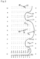
- FIG. 3 shows a knitting course diagram of an embodiment of the invention
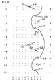
- FIG. 4 shows a knitting course diagram of the embodiment of the invention
- FIG. 5 shows a knitting course diagram of the embodiment of the invention
- FIG. 6 shows a loop diagram of the knitted fabric that was bound off in the knitting of the embodiment of the invention
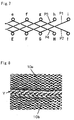
- FIG. 7 shows the cross of the courses of bind-off loops of the embodiment of the invention
- FIG. 8 shows the knitted fabric that was bound off in the knitting of the embodiment of the invention, when viewed from the inside thereof
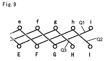
- FIG. 9 shows the cross of the courses of bind-off loops in the knitting of another embodiment of the invention.
- Bodies 2, 3 and right and left sleeves 4, 5 of a sweater 1 are knitted in the form of a tubular knitted fabric form, respectively, by using a number of needles in a plurality of regions on the needle beds. Thereafter, the right and left sleeves 4, 5 are transferred to and connected to the bodies 2, 3. At the point of time when the connection between the right and left sleeves 4, 5 and the bodies 2, 3 has been completed, the front body 2 and the back body 3 are connected to each other at both ends thereof, but are not yet connected to each other at the shoulder, as shown in FIG. 2. Stitches of a right front shoulder portion 7a and stitches of a left front shoulder portion 8a are held on the needles of the front needle bed across a nape opening 6.
- the right front shoulder portion 7a and the right back shoulder portion 7b, and the left front shoulder portion 8a and the left back shoulder portion 8b are connected to each other at the shoulder portions on the side on which the knitting is finished, so as to prevent loosening of stitches thereat.
- the right shoulder portion 7 and the left shoulder portion 8 are symmetrically knitted.
- description on the binding-off of the left shoulder portion 8 only will be given below.
- the left front shoulder portion 8a is described as a front knitted fabric 10a
- the left back shoulder portion 8b is described as a back knitted fabric 10b.
- a fewer number of needles than the actual number of needles is illustrated herein.
- the present invention is practically used with a flat knitting machine comprising at least two front and back needle beds, such as two or four needle beds, which are placed opposite in front and back and at least either of which is movable slidably transversely.
- a two-needle-bed flat knitting machine with only the back needle bed movable slidably transversely is used.
- FIGS. 3-5 the numerals at the left side indicate the serial number of the courses; the vertical arrows indicate the direction for the loops to be transferred; and the horizontal arrows indicate the knitting direction.
- the course 0 of FIG. 3 shows the state before starting the binding-off process.
- the front knitted fabric 10a is held on the needles A-I of the front needle bed, and the back knitted fabric 10b is held on the needles a-i of the back needle bed.
- a yarn feeder is shifted rightwards over a guide rail (not shown) arranged in the longitudinal direction of the needle bed along a needle bed gap between the front and back needle beds, to feed a yarn to the needles A-I of the front needle bed, for the knitting, and is in a right end of a binding-off process region.
- the front knitted fabric 10a and the back knitted fabric 10b are connected within the binding-off region ranging from the needles I, i at the right end to the needles A, a.
- the binding-off process is performed starting from the needle I of the front needle bed and the needle i of the back needle bed until the double loop of the loop of the last course of the knitted fabric and the bind-off loop is formed by the needle E of the front needle bed and the needle e of the back needle bed.
- the binding-off process is performed from the right side to the left side, as viewed in FIG. 1.
- the proceeding direction of the binding-off process means that the binding-off process proceeds from the right side to the left side.
- alphabetical letters represent which loop in the last course the loop is formed continuously with, and numeric characters represent what number of course from the last course of the knitted fabric the loop falls under.
- the loops of the last course of the front knitted fabric 10a are represented as E0, F0, ...; the bind-off loops formed continuously with the loops of the last course are represented as E1, F1, ...; and further the bind-off loops of the next course are represented as E2, F2, ....
- the loops of the last course of the back knitted fabric 10b are represented as e0, f0, ...; the bind-off loops formed continuously with the loops of the last course are represented as e1, f1, ...; and further the bind-off loops of the next course are represented as e2, f2, ....
- a yarn is fed to the needle i of the back needle bed by the yarn feeder to from a bind-off loop i1.
- the bind-off loop i1 is transferred to the needle J of the front needle bed.
- the yarn is fed to the needle J to form a bind-off loop i2.
- the bind-off loop i2 is transferred to the needle i of the back needle bed. Further, in the course 5, it is transferred to the needle G of the front needle bed in the course 5, to lay it over the loop G0 of the last course of the front knitted fabric 10a held on the needle G. In the course 6, the loop I0 of the front knitted fabric 10a held on the needle I of the front needle bed is transferred to the needle i of the back needle bed. In the course 7, the yarn is fed to the needle i to form the bind-off loop I1. In the course 8, after the bind-off loop I1 is transferred to the needle I of the front needle bed, the yarn is fed to the needle I to form the bind-off loop I2. Then, in the course 10, the newly formed bind-off loop I2 is transferred to the needle g of the back needle bed to lay it over the loop g0 of the back knitted fabric 10b.
- the yarn is fed to the needle h of the back needle bed to form a bind-off loop h1.
- the bind-off loop h1 is transferred to the needle I of the front needle bed.
- the yarn is fed to the needle I to form a bind-off loop h2.
- the bind-off loop h2 is transferred to the needle h of the back needle bed.
- it is further transferred to the needle F of the front needle bed to lay it over the loop F0 of the last course of the front knitted fabric 10a.
- the loop H0 of the front knitted fabric is transferred to the needle h of the back needle bed.
- the yarn is fed to the needle h to form a bind-off loop H1.
- the bind-off loop H1 is transferred to the front needle bed.
- the yarn is fed to the needle H to form a bind-off loop H2.
- the bind-off loop H2 is transferred to the needle f of the back needle bed to lay it over the loop f0 of the last course of the back knitted fabric 10b.
- the yarn is fed to the needle g of the back needle bed on which the double loop g0-I2 is held as a result of the knitting of the courses 1 to 10, to form a bind-off loop g1.
- the bind-off loop I2 formed continuously with the bind-off loop I1 is cleared from the needle and thus the number of stitches held on the needles reduces a stitch from the course 0.
- the newly formed bind-off loop g1 is transferred to the needle H of the front needle bed.
- the yarn is fed to the needle H of the front needle bed to form a bind-off loop g2.
- the bind-off loop g2 is transferred to the needle g of the back needle bed. Then, in the course 25, the bind-off loop g2 is transferred to the needle E of the front needle bed to lay it over the loop E0 of the last course of the front knitted fabric 10a. In the course 26, the double loop G0-i2 held on he needle G of the front needle bed is transferred to the needle g of the back needle bed. In the course 27, the yarn is fed to the needle g to form a bind-off loop G1. Then, in the course 28, the bind-off loop G1 is transferred to the front bed. Thereafter, in the course 29, the yarn is fed to the needle G of the front needle bed to form a bind-off loop G2.
- the bind-off loop G2 is transferred to the needle f of the back needle bed to lay it over the loop f0 of the back knitted fabric. Subsequently, the knitting shown in the courses 21 to 30 is repeated, while a group of target loops are each shifted a stitch to a group of loops positioned forward with respect to the proceeding direction of the binding-off direction, whereby the front knitted fabric 10a and the back knitted fabric 10b are joined.
- bind-off courses comprising a first bind-off course i1, i2, G1, G2, ... (indicated by P1 in FIG. 7) which is formed starting at the loop i0 at a side end of the back knitted fabric 10b, a second bind-off course I1, I2, g1, g2, ... (indicated by P2 in FIG. 7) which is formed starting at the loop I0 of the front knitted fabric 10a, a third bind-off course h1, h2, F1, F2, ... (indicated by P3 in FIG.
- three bind-off courses Q1, Q2 and Q3 may be formed from three groups of loops, for the binding off process of the fabric, as shown in FIG. 9.
- four or more bind-off courses may be formed from four or more groups of loops. It is to be noted that selection may be freely made on which form the bind-off loops formed continuously with the front knitted fabric 10a and the back knitted fabric 10b should be taken, the front stitch or the back stitch, and on what number of courses should be formed.
- the order in which the bind-off loops are formed may be changed.
- the embodiment wherein the fabric is knitted with the front knitted fabric 10a and the back knitted fabric 10b formed to be continuous with each other at both ends thereof has been described above, the binding-off process of the present invention may be practically applied to the case where the front knitted fabric 10a and the back knitted fabric 10b are knitted as separate knitted fabrics, as is the case with the binding-off process for e.g. a vest shoulder.
- the flat knitting machine is driven under control of a computer built in the flat knitting machine that reads and interprets the knitting command stored in a disc and the like to control the respective mechanisms of the flat knitting machine.
- the principal knitting processes including the bonding-off process are stored in the form of subroutines in a CAD system for designing a knitted fabric.
- This type of CAD system includes the computer and output equipment so that the knitting commands can be written on the disc and the like.
- the CAD system stores principal points, including the knitting points on tubular knitting, widening stitch or narrowing stitch, and binding off, in the form of subroutines.
- the subroutines associated with respective parts of the fabric designed by a user are properly combined with each other, so that the appropriate knitting commands are output.
- the knitting commands include the command for the flat knitting machine having the computer built-in to knit the fabric in accordance with the knitting commands.
- the flat knitting machine is driven under control of the built-in computer, while also the knitting commands stored in the disc and the like are read by the built-in computer and are interpreted by the CAD system, to reproduce a design picture of the fabric designed on the CAD system by the user.
- At least three bind-off courses which are formed starting at not less than three loops, i.e., loops of the first and second knitted fabrics at side ends thereof in the region of the binding-off process, as well as a loop adjoining to the loop of at least either of the first and second knitted fabrics at the side end, are allowed to extend in zigzag from the first knitted fabric to the second knitted fabric and vice versa, ranging over the region of the binding-off process, and the loops of the bind-off courses are each laid over the loop of the last course of the opposite knitted fabric.
- the bind-off courses are densely weaved in the bind-off portion of the fabric.
- a bind-off fabric with a gap between the front knitted fabric and the back knitted fabric closed is formed and also a stretch of the fabric in the widthwise direction of the fabric is suppressed to provide a reinforced fabric.
Landscapes
- Engineering & Computer Science (AREA)
- Textile Engineering (AREA)
- Knitting Of Fabric (AREA)
- Knitting Machines (AREA)
- Braiding, Manufacturing Of Bobbin-Net Or Lace, And Manufacturing Of Nets By Knotting (AREA)
Abstract
Description
wherein at least three bind-off courses are formed starting at not less than three loops, i.e., loops of the first and second knitted fabrics at side ends thereof in the region of the binding-off process, and a loop adjoining to the loop of at least either of the first and second knitted fabrics at the side end, and the loops of the respective bind-off courses are each laid over the loop of the last course of the opposite knitted fabric in such a manner as to extend in zigzag from the second knitted fabric to the first knitted fabric and vice versa, ranging over the region of the binding-off process, so as to be crossed with each other.
Claims (5)
- A binding-off process, which is performed by using a flat knitting machine comprising at least a pair of first and second needle beds, which have a number of needles, respectively, and are placed opposite in front and back; between which a needle bed gap is defined; and at least either of which is movable slidably transversely, and at least one yarn feeder for feeding a yarn to the needles of the first needle bed and the second needle bed and in which the knitting that a bind-off loop formed continuously with a loop in the last course of a tubular fabric comprising a first knitted fabric and a second knitted fabric is laid over a loop adjoining to the bind-off loop formed continuously with the loop in the last course of the fabric, to form a bind-off loop of the next course is repeated from one end of a region of the binding-off process toward the other end, to join the first and second knitted fabrics to each other on the side on which the knitting is finished, the binding-off process comprising:1) the process that at least three bind-off courses are formed starting at not less than three loops, i.e., loops of the first and second knitted fabrics at side ends thereof in the region of the binding-off process, and a loop adjoining to the loop of at least either of the first and second knitted fabrics at the side end, and2) the process that the bind-off loop formed is laid over the loop of the last course of the opposite knitted fabric in such a manner that while being formed, the respective bind-off courses can be allowed to extend in zigzag from the first knitted fabric to the second knitted fabric and vice versa, ranging over the region of the binding-off process, to be crossed with each other,.
- The binding-off process according to Claim 1, wherein the respective bind-off courses are formed in the process order:1) that the bind-off loops are formed at the loops of the first and second knitted fabrics at their respective side ends in the region of the binding-off process;2) that the bind-off loops formed in the process 1 are each laid over the loop in the last course of the opposite knitted fabric;3) that the bind-off loop is formed at the loop adjoining to the loop of at least either of the first and second knitted fabrics at the side end; and4) that the bind-off loops formed in the process 3 are each laid over the loop in the last course of the opposite knitted fabric.
- The binding-off process according to either of Claims 1 and 2, wherein four bind-off courses are formed starting at loops of the first and second knitted fabrics at side ends thereof in the region of the binding-off process, and loops adjoining to those loops of the first and second knitted fabrics at the side ends.
- A knitted fabric bound off in the binding-off process wherein a bind-off loop formed continuously with a loop in the last course of each of first and second knitted fabrics formed into a tubular fabric is laid over an adjoining loop in the last course to form a double loop so that the bind-off loop formed continuously with the double loop can form the bind off course extending continuously from one end of a region of the binding-off process toward the other end to join the first and second knitted fabric to each other,
wherein at least three bind-off courses are formed starting at not less than three loops, i.e., loops of the first and second knitted fabrics at side ends thereof in the region of the binding-off process, and a loop adjoining to the loop of at least either of the first and second knitted fabrics at the side end, and the loops of the respective bind-off courses are each laid over the loop of the last course of the opposite knitted fabric in such a manner as to extend in zigzag from the second knitted fabric to the first knitted fabric and vice versa, ranging over the region of the binding-off process, so as to be crossed with each other. - A CAD system used for a binding-off process which is performed by using a flat knitting machine comprising at least a pair of first and second needle beds, which have a number of needles, respectively, and are placed opposite in front and back; between which a needle bed gap is defined; and at least either of which is movable slidably transversely, and at least one yarn feeder for feeding a yarn to the needles of the first needle bed and the second needle bed, and in which the knitting that a bind-off loop formed continuously with a loop in the last course of a tubular fabric comprising first and second knitted fabrics is laid over a loop adjoining to the bind-off loop formed continuously with the loop in the last course of the fabric, to form a bind-off loop of the next course is repeated from one end of a region of the binding-off process toward the other end, to join the first and second knitted fabrics to each other on the side on which the knitting is finished, the CAD system being designed to give knitting commands for:1) the process of at least three bind-off courses being formed starting at not less than three loops, i.e., loops of the first and second knitted fabrics at side ends thereof in the region of the binding-off process and a loop adjoining to the loop of at least either of the first and second knitted fabrics at the side end, and2) the process that the loop of the bind-off course formed is laid over the loop of the last course of the opposite knitted fabric in such a manner that while being formed, the respective bind-off courses can be allowed to extend in zigzag from the first knitted fabric to the second knitted fabric and vice versa, ranging over the region of the binding-off process, to be crossed with each other.
Applications Claiming Priority (3)
| Application Number | Priority Date | Filing Date | Title |
|---|---|---|---|
| JP35875999 | 1999-12-17 | ||
| JP35875999 | 1999-12-17 | ||
| PCT/JP2000/008878 WO2001048286A1 (en) | 1999-12-17 | 2000-12-14 | Welt seaming method and welt-seamed knitted fabric, and cad device for welt seaming |
Publications (3)
| Publication Number | Publication Date |
|---|---|
| EP1253228A1 true EP1253228A1 (en) | 2002-10-30 |
| EP1253228A4 EP1253228A4 (en) | 2004-03-17 |
| EP1253228B1 EP1253228B1 (en) | 2008-06-18 |
Family
ID=18460974
Family Applications (1)
| Application Number | Title | Priority Date | Filing Date |
|---|---|---|---|
| EP00981732A Expired - Lifetime EP1253228B1 (en) | 1999-12-17 | 2000-12-14 | Welt seaming method and welt-seamed knitted fabric, and cad device for welt seaming |
Country Status (9)
| Country | Link |
|---|---|
| US (1) | US6658898B2 (en) |
| EP (1) | EP1253228B1 (en) |
| JP (1) | JP3881892B2 (en) |
| KR (1) | KR100643534B1 (en) |
| CN (1) | CN1273671C (en) |
| AU (1) | AU1890301A (en) |
| DE (1) | DE60039254D1 (en) |
| TW (1) | TW487754B (en) |
| WO (1) | WO2001048286A1 (en) |
Cited By (2)
| Publication number | Priority date | Publication date | Assignee | Title |
|---|---|---|---|---|
| EP2319969A1 (en) * | 2009-10-20 | 2011-05-11 | Shima Seiki Manufacturing., Ltd. | Knitting method of knitted fabric, and knitted fabric |
| EP2465983A4 (en) * | 2009-08-12 | 2013-03-20 | Shima Seiki Mfg | METHOD FOR FORMING FABRIC AND FABRIC |
Families Citing this family (11)
| Publication number | Priority date | Publication date | Assignee | Title |
|---|---|---|---|---|
| CN1283866C (en) * | 2001-03-26 | 2006-11-08 | 株式会社岛精机制作所 | Welt-processed knitted fabric and welt processing method |
| EP1626112B1 (en) * | 2003-04-21 | 2009-07-22 | Shima Seiki Mfg., Ltd | Method of joining knitting fabric |
| WO2011135653A1 (en) * | 2010-04-26 | 2011-11-03 | 株式会社島精機製作所 | Joining method of neighboring knitted fabric pieces, and knitted fabric |
| JP5669607B2 (en) * | 2010-07-23 | 2015-02-12 | 株式会社島精機製作所 | Knitting method of knitted fabric and knitted fabric |
| JP2012251262A (en) * | 2011-06-03 | 2012-12-20 | Shima Seiki Mfg Ltd | Knitting method of knitted fabric and knitted fabric |
| TWI585254B (en) * | 2013-04-23 | 2017-06-01 | 島精機製作所股份有限公司 | Method for knitting knitted fabric |
| JP6274908B2 (en) | 2014-02-27 | 2018-02-07 | 株式会社島精機製作所 | Knitting fabric bind off method |
| US9863070B2 (en) | 2014-12-08 | 2018-01-09 | Federal-Mogul Powertrain Llc | Tubular protective sleeve with curl resistant knit ends and method of construction thereof |
| CN110592788B (en) * | 2019-09-06 | 2021-04-23 | 惠州学院 | A kind of weaving method of imitation knitted knitted fabric |
| CN110616497B (en) * | 2019-09-18 | 2020-11-03 | 斓帛职业培训学校(桐乡)有限公司 | Double-needle-bed cylinder sleeving structure knitting method |
| CN114836887B (en) * | 2022-05-21 | 2024-05-24 | 嘉兴市蒂维时装有限公司 | Knitting method for automatic thread end hiding of full-forming under-clamping machine and knitted fabric |
Family Cites Families (6)
| Publication number | Priority date | Publication date | Assignee | Title |
|---|---|---|---|---|
| DE3203028C2 (en) * | 1982-01-29 | 1984-08-09 | H. Stoll Gmbh & Co, 7410 Reutlingen | Method for producing a knitted fabric |
| JPH0765258B2 (en) | 1990-07-17 | 1995-07-12 | 株式会社島精機製作所 | Knitted fabric edge treatment method |
| KR100392480B1 (en) * | 1995-04-10 | 2003-11-28 | 가부시키가이샤 시마세이키 세이사쿠쇼 | A method of binding off using a transverse knife and a method of binding- |
| JP3798062B2 (en) | 1995-04-10 | 2006-07-19 | 株式会社島精機製作所 | The bind-off method using a flat knitting machine and the knitted fabric that has been bind-down by this method |
| JP3044368B2 (en) | 1995-12-28 | 2000-05-22 | 株式会社島精機製作所 | A bind-off method, a knitted fabric treated by the bind-off method, and a CAD apparatus for generating the bind-off method |
| EP0781880B1 (en) * | 1995-12-28 | 2001-12-05 | Shima Seiki Manufacturing, Ltd. | Binding-off method, bound knitted fabric, and CAD apparatus therefor |
-
2000
- 2000-12-08 TW TW089126154A patent/TW487754B/en active
- 2000-12-14 EP EP00981732A patent/EP1253228B1/en not_active Expired - Lifetime
- 2000-12-14 DE DE60039254T patent/DE60039254D1/en not_active Expired - Lifetime
- 2000-12-14 JP JP2001548786A patent/JP3881892B2/en not_active Expired - Fee Related
- 2000-12-14 US US10/130,286 patent/US6658898B2/en not_active Expired - Fee Related
- 2000-12-14 KR KR1020027007104A patent/KR100643534B1/en not_active Expired - Fee Related
- 2000-12-14 AU AU18903/01A patent/AU1890301A/en not_active Abandoned
- 2000-12-14 WO PCT/JP2000/008878 patent/WO2001048286A1/en not_active Ceased
- 2000-12-14 CN CNB008171408A patent/CN1273671C/en not_active Expired - Fee Related
Cited By (2)
| Publication number | Priority date | Publication date | Assignee | Title |
|---|---|---|---|---|
| EP2465983A4 (en) * | 2009-08-12 | 2013-03-20 | Shima Seiki Mfg | METHOD FOR FORMING FABRIC AND FABRIC |
| EP2319969A1 (en) * | 2009-10-20 | 2011-05-11 | Shima Seiki Manufacturing., Ltd. | Knitting method of knitted fabric, and knitted fabric |
Also Published As
| Publication number | Publication date |
|---|---|
| EP1253228A4 (en) | 2004-03-17 |
| US20020189299A1 (en) | 2002-12-19 |
| CN1273671C (en) | 2006-09-06 |
| KR100643534B1 (en) | 2006-11-10 |
| US6658898B2 (en) | 2003-12-09 |
| DE60039254D1 (en) | 2008-07-31 |
| JP3881892B2 (en) | 2007-02-14 |
| TW487754B (en) | 2002-05-21 |
| WO2001048286A1 (en) | 2001-07-05 |
| CN1409779A (en) | 2003-04-09 |
| AU1890301A (en) | 2001-07-09 |
| EP1253228B1 (en) | 2008-06-18 |
| KR20020054363A (en) | 2002-07-06 |
Similar Documents
| Publication | Publication Date | Title |
|---|---|---|
| EP1375718B1 (en) | Knitted fabric having opening portion and knitting method therefor | |
| EP1306476B1 (en) | Welt-seaming method and welt-seamed knitted fabric, and cad device for welt-seaming | |
| US6070438A (en) | Bound knitted fabric | |
| US6672113B2 (en) | Method of knitting neck of knit wear by weft knitting machine and knit designing device for producing the method of knitting the neck | |
| US6658898B2 (en) | Binding-off process, bound off fabric, and CAD system for binding-off process | |
| EP2226417A1 (en) | Fabric knitting method, and fabric | |
| EP0826808B1 (en) | Method of knitting a collar | |
| US6581417B2 (en) | Knit wear knitting method | |
| US7693599B2 (en) | Method of knitting knitted fabric, knitting program for knitting knitted fabric, and knitted fabric | |
| US6748770B2 (en) | Method of linking tubular knitted fabrics together and knitted fabric therefor | |
| JP4852092B2 (en) | Method for forming additional stitches and knitted fabric in which additional stitches are formed on the inner side of the knitting width direction end of the knitted fabric | |
| JPWO2001055492A1 (en) | Method for knitting collars for knitwear using a flat knitting machine and knit design device for generating a method for knitting collars | |
| JPWO2002010494A1 (en) | Bound-off method, bound-off knitted fabric, and CAD device for binding-off | |
| EP0867547B1 (en) | A method of knitting tubular fabrics | |
| EP0940491B1 (en) | A widening method | |
| EP1471175B1 (en) | Neck forming method |
Legal Events
| Date | Code | Title | Description |
|---|---|---|---|
| PUAI | Public reference made under article 153(3) epc to a published international application that has entered the european phase |
Free format text: ORIGINAL CODE: 0009012 |
|
| 17P | Request for examination filed |
Effective date: 20020717 |
|
| AK | Designated contracting states |
Kind code of ref document: A1 Designated state(s): AT BE CH CY DE DK ES FI FR GB GR IE IT LI LU MC NL PT SE TR |
|
| AX | Request for extension of the european patent |
Free format text: AL;LT;LV;MK;RO;SI |
|
| A4 | Supplementary search report drawn up and despatched |
Effective date: 20040204 |
|
| RIC1 | Information provided on ipc code assigned before grant |
Ipc: 7D 04B 1/24 A |
|
| RBV | Designated contracting states (corrected) |
Designated state(s): DE ES FR GB IT |
|
| 17Q | First examination report despatched |
Effective date: 20070323 |
|
| GRAP | Despatch of communication of intention to grant a patent |
Free format text: ORIGINAL CODE: EPIDOSNIGR1 |
|
| GRAS | Grant fee paid |
Free format text: ORIGINAL CODE: EPIDOSNIGR3 |
|
| GRAA | (expected) grant |
Free format text: ORIGINAL CODE: 0009210 |
|
| AK | Designated contracting states |
Kind code of ref document: B1 Designated state(s): DE ES FR GB IT |
|
| REG | Reference to a national code |
Ref country code: GB Ref legal event code: FG4D |
|
| REF | Corresponds to: |
Ref document number: 60039254 Country of ref document: DE Date of ref document: 20080731 Kind code of ref document: P |
|
| PG25 | Lapsed in a contracting state [announced via postgrant information from national office to epo] |
Ref country code: ES Free format text: LAPSE BECAUSE OF FAILURE TO SUBMIT A TRANSLATION OF THE DESCRIPTION OR TO PAY THE FEE WITHIN THE PRESCRIBED TIME-LIMIT Effective date: 20080929 |
|
| PLBE | No opposition filed within time limit |
Free format text: ORIGINAL CODE: 0009261 |
|
| STAA | Information on the status of an ep patent application or granted ep patent |
Free format text: STATUS: NO OPPOSITION FILED WITHIN TIME LIMIT |
|
| 26N | No opposition filed |
Effective date: 20090319 |
|
| REG | Reference to a national code |
Ref country code: FR Ref legal event code: ST Effective date: 20090831 |
|
| PG25 | Lapsed in a contracting state [announced via postgrant information from national office to epo] |
Ref country code: FR Free format text: LAPSE BECAUSE OF NON-PAYMENT OF DUE FEES Effective date: 20081231 |
|
| PGFP | Annual fee paid to national office [announced via postgrant information from national office to epo] |
Ref country code: GB Payment date: 20101208 Year of fee payment: 11 |
|
| GBPC | Gb: european patent ceased through non-payment of renewal fee |
Effective date: 20121214 |
|
| PG25 | Lapsed in a contracting state [announced via postgrant information from national office to epo] |
Ref country code: GB Free format text: LAPSE BECAUSE OF NON-PAYMENT OF DUE FEES Effective date: 20121214 |
|
| PGFP | Annual fee paid to national office [announced via postgrant information from national office to epo] |
Ref country code: DE Payment date: 20171206 Year of fee payment: 18 |
|
| PGFP | Annual fee paid to national office [announced via postgrant information from national office to epo] |
Ref country code: IT Payment date: 20171221 Year of fee payment: 18 |
|
| REG | Reference to a national code |
Ref country code: DE Ref legal event code: R119 Ref document number: 60039254 Country of ref document: DE |
|
| PG25 | Lapsed in a contracting state [announced via postgrant information from national office to epo] |
Ref country code: DE Free format text: LAPSE BECAUSE OF NON-PAYMENT OF DUE FEES Effective date: 20190702 Ref country code: IT Free format text: LAPSE BECAUSE OF NON-PAYMENT OF DUE FEES Effective date: 20181214 |