EP1252452B1 - Tilter for positioning electronic devices - Google Patents
Tilter for positioning electronic devices Download PDFInfo
- Publication number
- EP1252452B1 EP1252452B1 EP00941182A EP00941182A EP1252452B1 EP 1252452 B1 EP1252452 B1 EP 1252452B1 EP 00941182 A EP00941182 A EP 00941182A EP 00941182 A EP00941182 A EP 00941182A EP 1252452 B1 EP1252452 B1 EP 1252452B1
- Authority
- EP
- European Patent Office
- Prior art keywords
- tilter
- hole
- tilt mount
- holes
- shaft
- Prior art date
- Legal status (The legal status is an assumption and is not a legal conclusion. Google has not performed a legal analysis and makes no representation as to the accuracy of the status listed.)
- Expired - Lifetime
Links
Images


Classifications
-
- F—MECHANICAL ENGINEERING; LIGHTING; HEATING; WEAPONS; BLASTING
- F16—ENGINEERING ELEMENTS AND UNITS; GENERAL MEASURES FOR PRODUCING AND MAINTAINING EFFECTIVE FUNCTIONING OF MACHINES OR INSTALLATIONS; THERMAL INSULATION IN GENERAL
- F16M—FRAMES, CASINGS OR BEDS OF ENGINES, MACHINES OR APPARATUS, NOT SPECIFIC TO ENGINES, MACHINES OR APPARATUS PROVIDED FOR ELSEWHERE; STANDS; SUPPORTS
- F16M11/00—Stands or trestles as supports for apparatus or articles placed thereon Stands for scientific apparatus such as gravitational force meters
- F16M11/20—Undercarriages with or without wheels
- F16M11/2007—Undercarriages with or without wheels comprising means allowing pivoting adjustment
- F16M11/2035—Undercarriages with or without wheels comprising means allowing pivoting adjustment in more than one direction
- F16M11/2064—Undercarriages with or without wheels comprising means allowing pivoting adjustment in more than one direction for tilting and panning
-
- F—MECHANICAL ENGINEERING; LIGHTING; HEATING; WEAPONS; BLASTING
- F16—ENGINEERING ELEMENTS AND UNITS; GENERAL MEASURES FOR PRODUCING AND MAINTAINING EFFECTIVE FUNCTIONING OF MACHINES OR INSTALLATIONS; THERMAL INSULATION IN GENERAL
- F16M—FRAMES, CASINGS OR BEDS OF ENGINES, MACHINES OR APPARATUS, NOT SPECIFIC TO ENGINES, MACHINES OR APPARATUS PROVIDED FOR ELSEWHERE; STANDS; SUPPORTS
- F16M11/00—Stands or trestles as supports for apparatus or articles placed thereon Stands for scientific apparatus such as gravitational force meters
- F16M11/02—Heads
- F16M11/04—Means for attachment of apparatus; Means allowing adjustment of the apparatus relatively to the stand
- F16M11/06—Means for attachment of apparatus; Means allowing adjustment of the apparatus relatively to the stand allowing pivoting
- F16M11/10—Means for attachment of apparatus; Means allowing adjustment of the apparatus relatively to the stand allowing pivoting around a horizontal axis
- F16M11/105—Means for attachment of apparatus; Means allowing adjustment of the apparatus relatively to the stand allowing pivoting around a horizontal axis the horizontal axis being the roll axis, e.g. for creating a landscape-portrait rotation
-
- F—MECHANICAL ENGINEERING; LIGHTING; HEATING; WEAPONS; BLASTING
- F16—ENGINEERING ELEMENTS AND UNITS; GENERAL MEASURES FOR PRODUCING AND MAINTAINING EFFECTIVE FUNCTIONING OF MACHINES OR INSTALLATIONS; THERMAL INSULATION IN GENERAL
- F16M—FRAMES, CASINGS OR BEDS OF ENGINES, MACHINES OR APPARATUS, NOT SPECIFIC TO ENGINES, MACHINES OR APPARATUS PROVIDED FOR ELSEWHERE; STANDS; SUPPORTS
- F16M2200/00—Details of stands or supports
- F16M2200/02—Locking means
- F16M2200/021—Locking means for rotational movement
- F16M2200/022—Locking means for rotational movement by friction
-
- Y—GENERAL TAGGING OF NEW TECHNOLOGICAL DEVELOPMENTS; GENERAL TAGGING OF CROSS-SECTIONAL TECHNOLOGIES SPANNING OVER SEVERAL SECTIONS OF THE IPC; TECHNICAL SUBJECTS COVERED BY FORMER USPC CROSS-REFERENCE ART COLLECTIONS [XRACs] AND DIGESTS
- Y10—TECHNICAL SUBJECTS COVERED BY FORMER USPC
- Y10S—TECHNICAL SUBJECTS COVERED BY FORMER USPC CROSS-REFERENCE ART COLLECTIONS [XRACs] AND DIGESTS
- Y10S248/00—Supports
- Y10S248/917—Video display screen support
- Y10S248/918—Ancillary device support associated with a video display screen
-
- Y—GENERAL TAGGING OF NEW TECHNOLOGICAL DEVELOPMENTS; GENERAL TAGGING OF CROSS-SECTIONAL TECHNOLOGIES SPANNING OVER SEVERAL SECTIONS OF THE IPC; TECHNICAL SUBJECTS COVERED BY FORMER USPC CROSS-REFERENCE ART COLLECTIONS [XRACs] AND DIGESTS
- Y10—TECHNICAL SUBJECTS COVERED BY FORMER USPC
- Y10S—TECHNICAL SUBJECTS COVERED BY FORMER USPC CROSS-REFERENCE ART COLLECTIONS [XRACs] AND DIGESTS
- Y10S248/00—Supports
- Y10S248/917—Video display screen support
- Y10S248/919—Adjustably orientable video screen support
- Y10S248/921—Plural angular
-
- Y—GENERAL TAGGING OF NEW TECHNOLOGICAL DEVELOPMENTS; GENERAL TAGGING OF CROSS-SECTIONAL TECHNOLOGIES SPANNING OVER SEVERAL SECTIONS OF THE IPC; TECHNICAL SUBJECTS COVERED BY FORMER USPC CROSS-REFERENCE ART COLLECTIONS [XRACs] AND DIGESTS
- Y10—TECHNICAL SUBJECTS COVERED BY FORMER USPC
- Y10T—TECHNICAL SUBJECTS COVERED BY FORMER US CLASSIFICATION
- Y10T403/00—Joints and connections
- Y10T403/32—Articulated members
- Y10T403/32254—Lockable at fixed position
- Y10T403/32262—At selected angle
-
- Y—GENERAL TAGGING OF NEW TECHNOLOGICAL DEVELOPMENTS; GENERAL TAGGING OF CROSS-SECTIONAL TECHNOLOGIES SPANNING OVER SEVERAL SECTIONS OF THE IPC; TECHNICAL SUBJECTS COVERED BY FORMER USPC CROSS-REFERENCE ART COLLECTIONS [XRACs] AND DIGESTS
- Y10—TECHNICAL SUBJECTS COVERED BY FORMER USPC
- Y10T—TECHNICAL SUBJECTS COVERED BY FORMER US CLASSIFICATION
- Y10T403/00—Joints and connections
- Y10T403/32—Articulated members
- Y10T403/32254—Lockable at fixed position
- Y10T403/32532—Clamped members
Definitions
- This invention relates generally to a tilter device for positioning electronic devices, and more particularly, to a tilter device suitable for adjustably positioning a flat-screen electronic peripheral device, such as a computer monitor or television.
- extension arms or stands used to support electronic devices are known in the prior art. Such extension arms attach to computer monitors, for example, allowing a user to then mount the arm to a desk, wall, or other appropriate surface. The arm enables the user to linearly position the device along one or more axis.
- One such extension arm is shown and described in Applicant's PCT patent application number PCT/US00/12594 filed on May 10, 2000 entitled “Arm Apparatus for Mounting Electronic Devices”.
- a tilter that allows a device to be rotated about one or more axis is typically employed. Tilters for various uses have been described in the prior art.
- U.S. Patent No. 4,047,684 to Kobayashi discloses an adjustable tilter device used for holding objects such as musical instruments. This tilter includes a stationary tilter block that attaches to a stand, along with a movable tilter block that detachably connects to the stationary tilter block.
- This tilter is not suitable for use with electronic devices because it lacks the appropriate means to attach to such a device.
- the device when an electronic device such as a computer monitor or a television were desired to be tiltable, the device was typically balanced on a horizontal platform that was attached to a tilter on its bottom face.
- the tilter either rested on a flat surface like a desk, in which case it required a wide base so as to prevent the device from tipping over when tilted, or else it was attached to an extension arm, in which case the tilter was required to made of heavy gauge material so as to accommodate the weight of the device.
- the tilters of the prior art are not well suited for use with flat-screen devices, such as flat-screen computer monitors and televisions. For instance, one of the reasons that flat-screen devices are increasing in popularity is due the fact that they require a minimal amount of space. When a tilter is employed with a flat-screen device, the tilter should not significantly increase the space which is occupied by the device. However, the tilters of the prior art do not minimize the space occupied by the device because these tilters are typically bulky. Furthermore, the prior art tilter which employs a horizontal platform as previously described, cannot be used with a flat-screen device, because flat-screen devices cannot be balanced on a horizontal platform, since their depth is insufficient to keep the device from tipping over.
- a flat-screen device is typically mounted in position by bolts, screws or other fastening devices that engage holes located on the back of the device.
- the VESA is currently considering several standards for the spacing and positioning of the holes located on the back of the flat-screen device to be mounted. Until a particular VESA standard has been adopted, manufacturers of flat-screen mounting devices, such as tilters, run the risk of designing and fabricating mounting devices that will be incompatible with the standard eventually adopted.
- tilter device that is suitable for mounting an electronic peripheral device, such as a flat-screen computer monitor or television, and that can accommodate various mounting standards.
- US, A, 5,226,622 discloses a fully adjustable portable trap stand comprising a mounting plate to which a trap can be attached, a base which allows the trap stand to be securely anchored, adjusting means which permit the mounting plate to be oriented through a wide range of directions with respect to the base, and locking means that substantially fixed the orientation of the mounting plate in spite of recoil forces applied to it by operation of an attached trap.
- US, A, 4,470,106 presents an improved shop light for being releasably mounted in a desired location for illuminating a work area.
- the shop light comprises a handle member, electricity means, a guard member, magnetic mounting means and a hook member.
- FR 1,123,300 relates to a support device that can be rotated in two directions.
- US, A, 4,034,946 describes a mount for removably mounting a light to a base member comprising a pair of clevis members.
- the tilter device is comprised of a center tilt mount pivotally attached to a support block, and a rotating adapter plate attached to the center tilt mount.
- the tilter device is attached to the electronic peripheral through the use of an adapter plate that can accommodate various mounting standards.
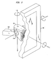
- the present invention in accordance with one embodiment, relates to a tilter 10, illustrated in Fig. 1 , capable of positioning a flat-screen electronic peripheral device 100 ( Fig. 2 ), such as a computer monitor, at user defined angles in relation to all three dimensions.
- the tilter 10 is configured so that it may be used in conjunction with an extension arm 200 (a portion of which is illustrated in Fig. 2 ) which is described in PCT patent application number PCT/US00/12594 filed on May 10, 2000 entitled “Arm Apparatus for Mounting Electronic Devices", or a polestand (not shown) which is described in co-pending U.S. patent application number 09/478,281 filed on January 5, 2000 entitled “Polestand Apparatus for Mounting Electronic Devices”.
- FIG. 1 illustrates an exploded assembly drawing of the tilter 10, according to one embodiment of the invention.
- the tilter 10 includes a support block 20 attached to a support block shaft 30, and a center tilt mount 40 pivotally attached to the support block 20 by a support block bushing 50, a tilter roller shaft 60, and a set screw 12.
- a rotating plate 70 is part of the configuration, it is attached to the center tilt mount 40 by, for example, a rivet 80.
- a washer 14 such as a nylon washer, is disposed between the two.
- An adapter plate 90 is connected to the rotating plate 70 (if the rotating plate 70 is part of the tilter 10 configuration) or is connected directly to the center tilt mount 40 (if the rotating plate 70 is not part of the tilter 10 configuration) with, for example, threaded fasteners (not shown).
- the tilter 10 may be securely attached to an appropriate surface, such as an extension arm 200.
- the support block shaft 30 is located within a coupling 210 in the extension arm 200 and is secured within the coupling 210 by using, for example, a washer 16 and a screw 18, such as, a steel washer and a pan head screw.
- the tilter 10 may securely attach to a flat screen device 100 by connecting the flat screen device 100 to the adapter plate 90 via standardized fastening regions (illustrated in Figs. 9a-9c ) disposed on both the adapter plate 90 and the flat-screen device 100.
- Figure 2 illustrates how the tilter 10 can be rotated around all three axis, i.e. the x-axis, the y-axis and the z-axis.
- the tilter 10 is rotated around the x-axis by rotating the center tilt mount 40 with respect to the support block 20 at the tilter roller shaft 60.
- the tilter 10 is rotated around the y-axis by rotating the support block shaft 30 within the coupling 210 of the extension arm 200.
- the tilter 10 is rotated around the z-axis by rotating the rotating plate 70 with respect to the center tilt mount 40 using the rivet 80.
- the extension arm 200 allows for linear movement along the x, y, and z-axis and the tilter 10 allows for rotation about the same axis.
- the tilter 10 will freely rotate about the axis of the support block shaft 30, the axis of the rivet 80, and the axis of the tilter roller shaft 60 upon loosening the set screw 12.
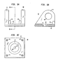
- the support block 20 is generally a cubical block which is cast from a relatively strong metal, such as zinc.
- the support block 20 has a bushing hole 22 formed therein.
- the support block 20 may have a sidewall 23 that is rounded so as to follow the shape of the bushing hole 22. This provides an equal amount of material supporting the outer edge of the bushing hole 22.
- the support block 20 will include a set screw boss 24.
- the set screw boss 24 provides material through which a tapped hole 26 is disposed.
- the tapped hole 26 communicates with a surface of the bushing hole 22.
- a shaft hole 28 is disposed in the support block 20.
- the shaft hole 28 nearly extends through the entire height of the support block 20 and is capable of receiving the support block shaft 30.
- Figure 4b illustrates that the support block shaft 30 is generally cylindrically shaped.
- the support block shaft 30 is fabricated from a strong lightweight material, preferably aluminum because of its relative strength, lightness, and ability to efficiently transfer heat.
- a diamond knurl band 32 is disposed about the circumference of the support block shaft 30, at a point on the support block shaft 30 that is approximately one-third of the distance from a first end to a second end of the support block shaft 30.
- the diameters of the support block shaft 30 and the shaft hole 28 are nearly the same.
- the knurl band 32 allows for a secure press fit between the support block shaft 30 and the support block 20.
- the support block shaft 30 may contain threaded holes 34 in an outer perimeter thereof to provide additional flexibility for mounting. As illustrated in Fig. 4b , the support block shaft 30 includes a threaded hole 36 provided therein at an axial centerline of the support block shaft 30. The threaded hole 36 receives the screw 18 which is threaded through the washer 16 (shown in Fig. 1 ) for the purpose of securing the tilter 10 to the coupling 210 of an extension arm 200 or other device.
- the tilter device 10 rotates around the axis of the support block shaft 30 (shown as the y-axis in Figure 2 ) which is perpendicular to the x-axis around which the center tilt mount 40 rotates relative to the support block 20 (as will be discussed further below).
- the center tilt mount 40 is cast from relatively lightweight, strong metal, such as aluminum.
- the center tilt mount 40 comprises a base 42 having a generally square shape, from which extend flanges 44. Stops 46, which are generally cubical shaped blocks, are formed on an inner surface of the base 42 adjacent to the flanges 44. The stops 46 serve to arrest the rotation of the center tilt mount 40 in the negative direction about the x-axis.
- the flanges 44 have shaft holes 48 formed therein for accepting the tilter roller shaft 60.
- the shaft holes 48 align with the bushing hole 22 so as to form an extended tubular passageway when the support block 20 is located between the flanges 44.
- a rivet hole 49 extends through the center of the base 42.
- the rivet hole 49 includes a recessed portion 41 upon which a head of the rivet 80 may securely fit.
- Figure 5c illustrates that the base 42 also includes a shallow washer channel 47, capable of receiving the washer 14.
- the shallow washer channel 47 preferably has a depth of approximately .016 inches.
- mounting holes 45 are disposed near corners of the base 42 and extend into the flanges 44. As discussed in more detail below, the mounting holes 45 allow the tilter 10 to be secured directly to the adapter plate 90.
- FIG. 6 illustrates that the tilter roller shaft 60 is generally cylindrically shaped. As with the support block shaft 30, the tilter roller shaft 60 is preferably fabricated from aluminum. A straight knurl band 62 is disposed at one end of the tilter roller shaft 60. Preferably the width of the knurl band 62 corresponds to the width of the flanges 44.
- a support block bushing 50 (shown in Fig. 1 ) is first inserted into the bushing hole 22.
- the support block bushing 50 is made of bronze and has a split running down the length of it (i.e., having a C cross-sectional profile). The split in the bronze allows the support block bushing 50 to be compressed and thus frictionally engage the tilter roller shaft 60, which prevents further rotation of the tilter roller shaft.
- the support block bushing 50 is fabricated from a smooth material, such as plastic, and preferably has flanges on each side.
- the support block bushing 50 provides a bearing surface upon which the tilter roller shaft 60 may rotate.
- Having the support block bushing 50 made of plastic provides a smooth surface which minimizes friction and avoids metal to metal contact between the support block 20 and the tilter roller shaft 60.
- a portion of the support block bushing 50 that protrudes from the bushing hole 22 acts as a washer between the support block 20 and inside surfaces of the flanges 44. This again minimizes friction, and avoids metal to metal contact between the flanges 44 and the tilter roller shaft 60.
- the non-knurled end of the tilter roller shaft 60 is inserted into one of the shaft holes 48.
- the knurl band 22 is press fit into a second one of the shaft holes 48.
- the set screw 12 is now screwed into the tapped hole 26 of the support block 20 so as to make contact with an outside portion of the support block bushing 50.
- the support block bushing 50 flexes inward.
- a portion of the support block bushing 50 frictionally engages the tilter roller shaft 60 and interferes with further rotation.
- the support block 20 and the center tilt mount 40 may once again rotate with respect to each other.
- Figure 7 illustrates the rotating plate 70 which is rotatably secured to the center tilt mount 40 by the rivet 80.
- the axis of rotation of the rotating plate 70 as illustrated in Fig. 2 , is perpendicular to the axis of rotation defined by the tilter roller shaft 60 around which the center tilt mount 40 rotates relative to the support block 20.
- the rotating plate 70 is generally square in shape and has a rivet hole 72 formed therethrough at the center.
- the rotating plate 70 also includes a recessed portion 74 disposed on a first surface thereof.
- the recessed portion 74 which is preferably circular in shape, allows the rivet 80 to protrude through the rivet hole 72 and not interfere with the adapter plate 90 which may be connected to the rotating plate 70.
- Four mounting holes 76 are disposed at the corners of the rotating plate 70. The mounting holes 76 are used to attach the rotating plate 70 to the adapter plate 90.
- the rotating plate 70 is optional. In certain applications, for example, when it is desired that the mounted electronic device is not rotatable about the z-axis, the rotating plate 70 would not be included in the tilter 10, instead the adapter plate 90 would be directly mounted to the center tilt mount 40.
- An example of a device where rotation about the z-axis would not be desired is a keyboard or a laptop computer. It would be desirable to rotate these devices about the x and y-axis defined in Fig. 2 , but it is unlikely that a user would require rotation about the z-axis.
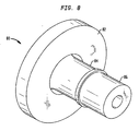
- the rivet 80 is preferably fabricated from a material that may be plastically deformed and is sufficiently malleable so as not to fracture during such deformation. As illustrated in Fig. 8 , the rivet 80 has a head 82 that fits within the recessed portion 41 of the center tilt mount 40 and.a first cylindrical portion 84 that has a diameter that corresponds to the diameter of the rivet holes 49 and 72. The length of the first cylindrical portion 84 is such that it may pass through the rivet holes 49 and 72.
- the rivet also includes a second cylindrical portion 86 having a smaller diameter than the first cylindrical portion 84. The second cylindrical portion 86 protrudes above the surface of the recessed portion 74.
- a riveting machine is used to deform the second cylindrical portion 86 so that its diameter becomes larger than diameters of the rivet holes 49 and 72 causing the rotating plate 70 to be secured to the center tilt mount 40.
- the washer 14 ( Fig. 1 ) is placed in the shallow washer channel 47.
- the washer 14 serves to protect surfaces of the center tilt mount 40 during rotation of the rotating plate 70.
- the riveting machine may also determine the appropriate level of friction such that the rotating plate 70 is secured to the center tilt mount 40, while the rotating plate 70 remains capable of freely rotating about the axis of the rivet 80.
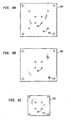
- FIGS 9a-c illustrate three embodiments of the adapter plate 90.
- the adapter plate 90 is preferably fabricated from a strong material such as metal, and is preferably steel. All of the embodiments of the adapter plate 90 have holes 92 that are aligned with the mounting holes 45 and 76, so that the adapter plate can be mounted to either the center tilt mount 40 or the rotating plate 70.
- the adapter plate 90 is mounted to either the center tilt mount 40 or the rotating plate 70 by inserting a fastener, such as a screw or pin through the holes 92 and into either of the mounting holes 45 or 76.
- the mounting holes 45 and 76 are threaded and the fastener is a threaded fastener that can be screwed into the appropriate mounting holes 45 or 76.
- the embodiment of the adapter plate 90a illustrated in Fig. 9a has fastening regions consisting of holes 94 and 96 that are positioned to correspond to two individually proposed VESA standards, a so-called large standard and a so-called small standard.
- VESA has not selected whether the so-called large standard or the so-called small standard is the final standard.
- the holes 94 are for the so-called small standard, and form the corners of a square having side lengths equal to 75 mm.
- the holes 96 are for the so-called large standard, and form the corners of a square having side lengths equal to 100 mm.
- the adapter plate 90a can be attached to a flat-screen device with threaded fasteners (not shown), or other means.
- the embodiment of the adapter plate 90b illustrated in Fig. 9b has fastening regions consisting of holes 96 corresponding to only the so-called large standard.
- the embodiment of the adapter plate 90c illustrated in Fig. 9c has fastening regions consisting of holes 94 corresponding to only the so-called small standard. It is understood that the adapter plate 90 may also contain other holes that form other configurations and have other dimensions.
Abstract
Description
- This invention relates generally to a tilter device for positioning electronic devices, and more particularly, to a tilter device suitable for adjustably positioning a flat-screen electronic peripheral device, such as a computer monitor or television.
- Mechanical extension arms or stands used to support electronic devices are known in the prior art. Such extension arms attach to computer monitors, for example, allowing a user to then mount the arm to a desk, wall, or other appropriate surface. The arm enables the user to linearly position the device along one or more axis. One such extension arm is shown and described in Applicant's
PCT patent application number PCT/US00/12594 filed on May 10, 2000 entitled "Arm Apparatus for Mounting Electronic Devices". - In order that a device may be positioned with even greater precision, a tilter that allows a device to be rotated about one or more axis is typically employed. Tilters for various uses have been described in the prior art. For example,
U.S. Patent No. 4,047,684 to Kobayashi discloses an adjustable tilter device used for holding objects such as musical instruments. This tilter includes a stationary tilter block that attaches to a stand, along with a movable tilter block that detachably connects to the stationary tilter block. This tilter, however, is not suitable for use with electronic devices because it lacks the appropriate means to attach to such a device. - In the prior art, when an electronic device such as a computer monitor or a television were desired to be tiltable, the device was typically balanced on a horizontal platform that was attached to a tilter on its bottom face. The tilter either rested on a flat surface like a desk, in which case it required a wide base so as to prevent the device from tipping over when tilted, or else it was attached to an extension arm, in which case the tilter was required to made of heavy gauge material so as to accommodate the weight of the device.
- However, the tilters of the prior art are not well suited for use with flat-screen devices, such as flat-screen computer monitors and televisions. For instance, one of the reasons that flat-screen devices are increasing in popularity is due the fact that they require a minimal amount of space. When a tilter is employed with a flat-screen device, the tilter should not significantly increase the space which is occupied by the device. However, the tilters of the prior art do not minimize the space occupied by the device because these tilters are typically bulky. Furthermore, the prior art tilter which employs a horizontal platform as previously described, cannot be used with a flat-screen device, because flat-screen devices cannot be balanced on a horizontal platform, since their depth is insufficient to keep the device from tipping over.
- Another problem associated with the prior art tilters is how to attach a flat-screen device to a mounting surface. Regardless of the type of extension arm employed and regardless of whether a tilter is employed, a flat-screen device is typically mounted in position by bolts, screws or other fastening devices that engage holes located on the back of the device. The VESA is currently considering several standards for the spacing and positioning of the holes located on the back of the flat-screen device to be mounted. Until a particular VESA standard has been adopted, manufacturers of flat-screen mounting devices, such as tilters, run the risk of designing and fabricating mounting devices that will be incompatible with the standard eventually adopted.
- Thus, there is a need for a tilter device that is suitable for mounting an electronic peripheral device, such as a flat-screen computer monitor or television, and that can accommodate various mounting standards.
-
US, A, 5,226,622 discloses a fully adjustable portable trap stand comprising a mounting plate to which a trap can be attached, a base which allows the trap stand to be securely anchored, adjusting means which permit the mounting plate to be oriented through a wide range of directions with respect to the base, and locking means that substantially fixed the orientation of the mounting plate in spite of recoil forces applied to it by operation of an attached trap. -
US, A, 4,470,106 presents an improved shop light for being releasably mounted in a desired location for illuminating a work area. The shop light comprises a handle member, electricity means, a guard member, magnetic mounting means and a hook member. -
FR 1,123,300 -
US, A, 4,034,946 describes a mount for removably mounting a light to a base member comprising a pair of clevis members. - It is a primary object of the present invention to provide an adjustable tilter device used for holding an object, such as an electronic peripheral, which enables a user to rotate the object at angles relative to one or more axis.
- In accordance with one embodiment of the present invention, the tilter device is comprised of a center tilt mount pivotally attached to a support block, and a rotating adapter plate attached to the center tilt mount. The tilter device is attached to the electronic peripheral through the use of an adapter plate that can accommodate various mounting standards.
- The above description sets forth rather broadly the more important features of the present invention in order that the detailed description thereof that follows may be understood, and in order that the present contributions to the art may be better appreciated. Other objects and features of the present invention will become apparent from the following detailed description considered in conjunction with the accompanying drawings. It is to be understood, however, that the drawings are not necessarily drawn to scale and are merely conceptual in nature and are designed solely for the purposes of illustration and not as a definition of the limits of the invention, for which reference should be made to the appended claims.
- The accompanying drawings, which are incorporated in and form a part of the specification, illustrate the embodiments of the present invention and, together with the description, serve to explain the principles of the invention.
-
Fig. 1 is an exploded view of a tilter, according to one embodiment of the invention; -
Fig. 2 is a perspective view of the tilter ofFig. 1 illustrating the various axis of rotation; -
Fig. 3a is a side view of a support block, according to one embodiment of the invention; -
Fig. 3b is a bottom view of the support block ofFig. 3a , according to one embodiment of the invention; -
Fig. 4a is a side view of a support block shaft, according to one embodiment of the invention; -
Fig. 4b is a bottom view of the support block shaft ofFig. 4a , according to one embodiment of the invention; -
Fig. 5a is a front view of a center tilt mount, according to one embodiment of the invention; -
Fig. 5b is a sectional view along line A-A of the center tilt mount ofFig. 5a , according to one embodiment of the invention; -
Fig. 5c is bottom view of the center tilt mount ofFig. 5a , according to one embodiment of the invention; -
Fig. 6 is a side view of a tilter roller shaft, according to one embodiment of the invention; -
Fig. 7 is a front view of a rotating plate, according to one embodiment of the invention; -
Fig. 8 is a perspective view of a rivet, according to one embodiment of the invention; -
Fig. 9a is a front view of an adapter plate, according to one embodiment of the invention; -
Fig. 9b is a front view of an adapter plate, according to one embodiment of the invention; and -
Fig. 9c is a front view of an adapter plate, according to one embodiment of the invention. - In describing the preferred embodiments of the invention illustrated in the drawings, specific terminology will be used for the sake of clarity. However, the invention is not intended to be limited to the specific terms so selected, and it is to be understood that each specific term includes all technical equivalents that operate in a similar manner to accomplish a similar purpose.
- With reference to the drawings, in general, and
Figs. 1 through 9 in particular, the apparatus of the present invention is disclosed. The present invention, in accordance with one embodiment, relates to atilter 10, illustrated inFig. 1 , capable of positioning a flat-screen electronic peripheral device 100 (Fig. 2 ), such as a computer monitor, at user defined angles in relation to all three dimensions. Thetilter 10 is configured so that it may be used in conjunction with an extension arm 200 (a portion of which is illustrated inFig. 2 ) which is described inPCT patent application number PCT/US00/12594 filed on May 10, 2000 entitled "Arm Apparatus for Mounting Electronic Devices", or a polestand (not shown) which is described in co-pendingU.S. patent application number 09/478,281 filed on January 5, 2000 -
Figure 1 illustrates an exploded assembly drawing of thetilter 10, according to one embodiment of the invention. Thetilter 10 includes asupport block 20 attached to asupport block shaft 30, and a center tilt mount 40 pivotally attached to thesupport block 20 by asupport block bushing 50, atilter roller shaft 60, and aset screw 12. If arotating plate 70 is part of the configuration, it is attached to the center tilt mount 40 by, for example, arivet 80.
Preferably, before attaching therotating plate 70 to thecenter tilt mount 40, awasher 14, such as a nylon washer, is disposed between the two. Anadapter plate 90 is connected to the rotating plate 70 (if therotating plate 70 is part of thetilter 10 configuration) or is connected directly to the center tilt mount 40 (if therotating plate 70 is not part of thetilter 10 configuration) with, for example, threaded fasteners (not shown). Thetilter 10 may be securely attached to an appropriate surface, such as anextension arm 200. Thesupport block shaft 30 is located within acoupling 210 in theextension arm 200 and is secured within thecoupling 210 by using, for example, awasher 16 and ascrew 18, such as, a steel washer and a pan head screw. Thetilter 10 may securely attach to aflat screen device 100 by connecting theflat screen device 100 to theadapter plate 90 via standardized fastening regions (illustrated inFigs. 9a-9c ) disposed on both theadapter plate 90 and the flat-screen device 100. -
Figure 2 illustrates how thetilter 10 can be rotated around all three axis, i.e. the x-axis, the y-axis and the z-axis. Thetilter 10 is rotated around the x-axis by rotating the center tilt mount 40 with respect to thesupport block 20 at thetilter roller shaft 60. Thetilter 10 is rotated around the y-axis by rotating thesupport block shaft 30 within thecoupling 210 of theextension arm 200. Thetilter 10 is rotated around the z-axis by rotating therotating plate 70 with respect to the center tilt mount 40 using therivet 80. When using thetilter 10 in conjunction with theextension arm 200, theextension arm 200 allows for linear movement along the x, y, and z-axis and thetilter 10 allows for rotation about the same axis. Thetilter 10 will freely rotate about the axis of thesupport block shaft 30, the axis of therivet 80, and the axis of thetilter roller shaft 60 upon loosening theset screw 12. - As illustrated in
Figs. 3a and 3b , thesupport block 20 is generally a cubical block which is cast from a relatively strong metal, such as zinc. Thesupport block 20 has abushing hole 22 formed therein. Thesupport block 20 may have asidewall 23 that is rounded so as to follow the shape of thebushing hole 22. This provides an equal amount of material supporting the outer edge of thebushing hole 22. If thesupport block 20 has the roundedsidewall 23, then thesupport block 20 will include aset screw boss 24. As illustrated inFig. 3b , theset screw boss 24 provides material through which a tappedhole 26 is disposed. The tappedhole 26 communicates with a surface of thebushing hole 22. Ashaft hole 28 is disposed in thesupport block 20. Theshaft hole 28 nearly extends through the entire height of thesupport block 20 and is capable of receiving thesupport block shaft 30. -
Figure 4b illustrates that thesupport block shaft 30 is generally cylindrically shaped. Thesupport block shaft 30 is fabricated from a strong lightweight material, preferably aluminum because of its relative strength, lightness, and ability to efficiently transfer heat. As illustrated inFig. 4a , adiamond knurl band 32 is disposed about the circumference of thesupport block shaft 30, at a point on thesupport block shaft 30 that is approximately one-third of the distance from a first end to a second end of thesupport block shaft 30. The diameters of thesupport block shaft 30 and theshaft hole 28 are nearly the same. Thus, upon inserting thesupport block shaft 30 into theshaft hole 28, theknurl band 32 allows for a secure press fit between thesupport block shaft 30 and thesupport block 20. Thesupport block shaft 30 may contain threadedholes 34 in an outer perimeter thereof to provide additional flexibility for mounting. As illustrated inFig. 4b , thesupport block shaft 30 includes a threadedhole 36 provided therein at an axial centerline of thesupport block shaft 30. The threadedhole 36 receives thescrew 18 which is threaded through the washer 16 (shown inFig. 1 ) for the purpose of securing thetilter 10 to thecoupling 210 of anextension arm 200 or other device. Thetilter device 10 rotates around the axis of the support block shaft 30 (shown as the y-axis inFigure 2 ) which is perpendicular to the x-axis around which thecenter tilt mount 40 rotates relative to the support block 20 (as will be discussed further below). - With reference to
Figs. 5a-c , thecenter tilt mount 40 is cast from relatively lightweight, strong metal, such as aluminum. As shown inFig. 5a , thecenter tilt mount 40 comprises a base 42 having a generally square shape, from which extendflanges 44.Stops 46, which are generally cubical shaped blocks, are formed on an inner surface of the base 42 adjacent to theflanges 44. The stops 46 serve to arrest the rotation of the center tilt mount 40 in the negative direction about the x-axis. As illustrated inFig. 5b , theflanges 44 have shaft holes 48 formed therein for accepting thetilter roller shaft 60. The shaft holes 48 align with thebushing hole 22 so as to form an extended tubular passageway when thesupport block 20 is located between theflanges 44. Arivet hole 49 extends through the center of thebase 42. Therivet hole 49 includes a recessedportion 41 upon which a head of therivet 80 may securely fit. -
Figure 5c illustrates that the base 42 also includes ashallow washer channel 47, capable of receiving thewasher 14. Theshallow washer channel 47 preferably has a depth of approximately .016 inches. Additionally, mountingholes 45 are disposed near corners of thebase 42 and extend into theflanges 44. As discussed in more detail below, the mountingholes 45 allow thetilter 10 to be secured directly to theadapter plate 90. -
Figure 6 illustrates that thetilter roller shaft 60 is generally cylindrically shaped. As with thesupport block shaft 30, thetilter roller shaft 60 is preferably fabricated from aluminum. Astraight knurl band 62 is disposed at one end of thetilter roller shaft 60. Preferably the width of theknurl band 62 corresponds to the width of theflanges 44. - In order to pivotally attach the
support block 20 and thecenter tilt mount 40, a support block bushing 50 (shown inFig. 1 ) is first inserted into thebushing hole 22. In a preferred embodiment, thesupport block bushing 50 is made of bronze and has a split running down the length of it (i.e., having a C cross-sectional profile). The split in the bronze allows thesupport block bushing 50 to be compressed and thus frictionally engage thetilter roller shaft 60, which prevents further rotation of the tilter roller shaft. - In an alternative embodiment, the
support block bushing 50 is fabricated from a smooth material, such as plastic, and preferably has flanges on each side. Thesupport block bushing 50 provides a bearing surface upon which thetilter roller shaft 60 may rotate. Having thesupport block bushing 50 made of plastic provides a smooth surface which minimizes friction and avoids metal to metal contact between thesupport block 20 and thetilter roller shaft 60. Moreover, a portion of thesupport block bushing 50 that protrudes from thebushing hole 22 acts as a washer between thesupport block 20 and inside surfaces of theflanges 44. This again minimizes friction, and avoids metal to metal contact between theflanges 44 and thetilter roller shaft 60. - After the shaft holes 48 and the
bushing hole 22 are aligned, the non-knurled end of thetilter roller shaft 60 is inserted into one of the shaft holes 48. Through the application of an appropriate force, theknurl band 22 is press fit into a second one of the shaft holes 48. Theset screw 12 is now screwed into the tappedhole 26 of thesupport block 20 so as to make contact with an outside portion of thesupport block bushing 50. As theset screw 12 presses against the circumference of thesupport block bushing 50, thesupport block bushing 50 flexes inward.
Thus, a portion of thesupport block bushing 50 frictionally engages thetilter roller shaft 60 and interferes with further rotation. By loosening theset screw 12, thesupport block 20 and thecenter tilt mount 40 may once again rotate with respect to each other. -
Figure 7 illustrates therotating plate 70 which is rotatably secured to the center tilt mount 40 by therivet 80. The axis of rotation of therotating plate 70, as illustrated inFig. 2 , is perpendicular to the axis of rotation defined by thetilter roller shaft 60 around which thecenter tilt mount 40 rotates relative to thesupport block 20. The rotatingplate 70 is generally square in shape and has arivet hole 72 formed therethrough at the center. The rotatingplate 70 also includes a recessedportion 74 disposed on a first surface thereof. The recessedportion 74, which is preferably circular in shape, allows therivet 80 to protrude through therivet hole 72 and not interfere with theadapter plate 90 which may be connected to therotating plate 70. Four mountingholes 76 are disposed at the corners of therotating plate 70. The mounting holes 76 are used to attach therotating plate 70 to theadapter plate 90. - It should be understood that the
rotating plate 70 is optional. In certain applications, for example, when it is desired that the mounted electronic device is not rotatable about the z-axis, the rotatingplate 70 would not be included in thetilter 10, instead theadapter plate 90 would be directly mounted to thecenter tilt mount 40. An example of a device where rotation about the z-axis would not be desired is a keyboard or a laptop computer. It would be desirable to rotate these devices about the x and y-axis defined inFig. 2 , but it is unlikely that a user would require rotation about the z-axis. - The
rivet 80 is preferably fabricated from a material that may be plastically deformed and is sufficiently malleable so as not to fracture during such deformation. As illustrated inFig. 8 , therivet 80 has ahead 82 that fits within the recessedportion 41 of the center tilt mount 40 and.a firstcylindrical portion 84 that has a diameter that corresponds to the diameter of the rivet holes 49 and 72. The length of the firstcylindrical portion 84 is such that it may pass through the rivet holes 49 and 72. The rivet also includes a secondcylindrical portion 86 having a smaller diameter than the firstcylindrical portion 84. The secondcylindrical portion 86 protrudes above the surface of the recessedportion 74. - A riveting machine is used to deform the second
cylindrical portion 86 so that its diameter becomes larger than diameters of the rivet holes 49 and 72 causing therotating plate 70 to be secured to thecenter tilt mount 40. Before attaching therotating plate 70 to thecenter tilt mount 40, the washer 14 (Fig. 1 ) is placed in theshallow washer channel 47. Thewasher 14 serves to protect surfaces of the center tilt mount 40 during rotation of therotating plate 70. The riveting machine may also determine the appropriate level of friction such that therotating plate 70 is secured to thecenter tilt mount 40, while therotating plate 70 remains capable of freely rotating about the axis of therivet 80. -
Figures 9a-c illustrate three embodiments of theadapter plate 90. Theadapter plate 90 is preferably fabricated from a strong material such as metal, and is preferably steel. All of the embodiments of theadapter plate 90 haveholes 92 that are aligned with the mountingholes rotating plate 70. Theadapter plate 90 is mounted to either the center tilt mount 40 or therotating plate 70 by inserting a fastener, such as a screw or pin through theholes 92 and into either of the mountingholes holes - The embodiment of the adapter plate 90a illustrated in
Fig. 9a has fastening regions consisting ofholes 94 and 96 that are positioned to correspond to two individually proposed VESA standards, a so-called large standard and a so-called small standard. Presently, VESA has not selected whether the so-called large standard or the so-called small standard is the final standard. The holes 94 are for the so-called small standard, and form the corners of a square having side lengths equal to 75 mm. Theholes 96 are for the so-called large standard, and form the corners of a square having side lengths equal to 100 mm. Thus, no matter which standard is ultimately selected, the adapter plate 90a can be attached to a flat-screen device with threaded fasteners (not shown), or other means. - The embodiment of the adapter plate 90b illustrated in
Fig. 9b has fastening regions consisting ofholes 96 corresponding to only the so-called large standard. The embodiment of the adapter plate 90c illustrated inFig. 9c has fastening regions consisting of holes 94 corresponding to only the so-called small standard. It is understood that theadapter plate 90 may also contain other holes that form other configurations and have other dimensions. - Although this invention has been illustrated by reference to specific embodiments, it will be apparent to those skilled in the art that various changes and modifications may be made that clearly fall within the scope of the invention. The invention is intended to be protected within the scope of the claims.
Claims (42)
- A tilter for adjustably mounting a device to a support mount, said tilter comprising:a support block (20) configured for pivotably engaging the support mount around a vertical first axis (Y), said support block having a bushing hole (22) therein;a shaft (30) attached to said support block extending away from said support block along said vertical first axis (Y), said shaft (30) adapted for engagement with said support mount whereby said support block is pivotable around said first vertical axis;a center tilt mount (40) coupled to and configured to pivotally engage said support block around a horizontal second axis (X), wherein the second axis (X) is perpendicular to the first axis (Y), said center tilt mount having a shaft hole (48) aligned with said bushing hole (22) in said support block;a bushing (50) received within the aligned bushing hole (22) and shaft hole (48);a tilter shaft (60) received within said bushing so as to pivotably couple said center tilt mount to said support block;a set screw (12) threadingly received within a portion of said support block, said set screw (12) having an end portion adapted to engage said bushing in the aligned bushing hole (20) and shaft hole (48), whereby said bushing (50) frictionally engages said tilter shaft (60) to prevent relative rotation between said center tilt mount and said support block; andan adapter plate (90) coupled to said tilt mount and configured to attach to the device.
- The tilter according to claim 1, further comprising a rotating plate (70) configured to be secured to said adapter plate (90) and to be rotatably secured to said center tilt mount (40) so as to permit pivotal rotation of said adapter plate (90) relative to said center tilt mount (40) around a third axis, wherein the third axis is perpendicular to the second axis.
- The tilter according to claim 2, wherein said rotating plate (70) is rotatably secured to said center tilt mount (40) by a rivet (80).
- The tilter according to claim 2, wherein said rotating plate (70) has a first plurality of holes (76) formed therein and said adapter plate (90) has a second plurality of holes (96) formed therein that is aligned with said first plurality of holes, said aligned holes configured to receive a plurality of fasteners so as to secure said adapter plate (90) to said rotating plate (70).
- The tilter according to claim 1, wherein said center tilt mount (40) has a first plurality of holes (45) formed therein and said adapter plate (90) has a second plurality of holes (96) formed therein that is aligned with said first plurality of holes (45), said aligned holes configured to receive a plurality of fasteners so as to secure said adapter plate to said center tilt mount.
- The tilter according to claim 1, wherein said support block (20) has a threaded hole therein for receiving a set screw, said set screw (12) configured to engage said bushing (50) in said opening (22) of said support block so as to deform said bushing (50), said deformed bushing frictionally engaging said tilter shaft (60) so as to prevent relative rotation therebetween.
- The tilter according to claim 1, wherein said tilter shaft has a knurl band (62) located at one end.
- The tilter according to claim 2, wherein said center tilt mount (40) includes a groove formed on a surface thereof.
- The tilter according to claim 8, further comprising a washer (14), said washer configured to be received in said groove on said center tilt mount (40) so as to be interposed between said center tilt mount (40) and said rotating plate (70).
- The tilter according to claim 3, wherein said center tilt mount (40) includes a groove formed on a surface thereof.
- The tilter according to claim 10, wherein said rivet (80) includes a head that contacts said center tilt mount within said groove.
- The tilter according to claim 1, wherein said adapter plate (90) includes four holes (96) forming corners of a square having sides of approximately 100 millimeters.
- The tilter according to claim 1, wherein said adapter plate (90) includes four holes forming corners of a square (96) having sides of approximately 75 millimeters.
- The tilter according to claim 1, wherein said adapter plate (90) includes a first set of four holes (94) forming corners of a first square having sides of approximately 75 millimeters and a second set of four holes (96) forming corners of a second square having sides of approximately 100 millimeters.
- The tilter according to claim 1, wherein the device is a flat-screen television.
- The tilter according to claim 1, wherein the device is a flat-screen computer monitor.
- The tilter according to claim 1, wherein the device is a keyboard.
- The tilter according to claim 1, wherein the device is a laptop computer.
- The tilter according to claim 1, wherein:said center tilt mount (40) has a floor (42) and sidewalls (44) extending therefrom, each said sidewall (44) having a hole (48) formed therein, each said sidewall hole (48) aligned with said other sidewall holes and said bushing body hole (22), at least one stop member (46) extending from said floor between said sidewalls; andwherein said at least one stop member (46) is adapted to arrest the rotation of said center tilter about said tilter shaft upon engagement with a portion of said support block (20).
- The tilter of claim 19, wherein said adapter plate (90) includes a plurality of holes (94, 96), said plurality of holes form at least one configuration associated with at least one mounting standard.
- The tilter of claim 19, wherein said adapter plate (90) is connected to the device with fasteners.
- The tilter of claim 21, wherein said fasteners are screws.
- The tilter of claim 19, wherein said center tilt mount (40) includes a plurality of mounting holes (45) formed in said floor (42) and said adapter plate (90) includes a plurality of holes (96) that align with said mounting holes.
- The tilter of claim 19, wherein said adapter plate (90) is connected to said center tilt mount (40) with fasteners.
- The tilter of claim 24, wherein said fasteners are screws.
- The tilter of claim 18, further comprising a rotating plate (70) coupled to said center tilt mount (40).
- The tilter of claim 26, wherein said floor (42) has a hole (49) formed therein, said floor hole (49) having an axial centerline aligned with a third axis (z) that is perpendicular to the first axis (x) and the second axis (y), said rotating plate (70) having a hole (72) formed therein that is aligned with said floor hole (49), and further comprising means for connecting said rotating plate (70) and said center tilt mount (40).
- The tilter plate of claim 27, wherein said means for connecting said rotating plate (70) and said center tilt mount (40) is a rivet (80).
- The tilter of claim 28, wherein said rivet (80) is inserted through said floor hole (49) and said rotating plate hole (72).
- The tilter of claim 28, wherein said rivet (80) includes a head (82) and a shaft (84, 86), said rivet being inserted through said floor hole (49) and said rotating plate hole (72) so that said rivet head (82) contacts said floor (42) and a portion of said rivet shaft (84, 86) protrudes above said rotating plate hole (72).
- The tilter of claim 30, further comprising means for securing said shaft (84, 86) within said rotating plate hole (72).
- The tilter of claim 30, wherein said portion of said rivet shaft (84, 86) protruding above said rotating plate hole (72) is deformed, said deformed portion having a diameter larger than a diameter of said rotating plate hole (72) so as to secure said rotating plate (70) to said center tilt mount (40) while allowing said rotating plate (70) to rotate around said center tilt mount (40).
- The tilter of claim 30, wherein said floor (42) includes an indented region (41) formed in a surface thereof, said indented region (41) having a nearly identical shape and depth as said rivet head (82), and said rivet head (82) contacts said center tilt mount (40) within said indented (41) region.
- The tilter of claim 26, wherein said rotating plate (70) includes a plurality of mounting holes (76) formed therein and said adapter plate (90) includes a plurality of holes (96) that align with said mounting holes (76).
- The tilter of claim 26, wherein said adapter plate (90) is connected to said center tilt mount (40) with fasteners.
- The tilter of claim 35, wherein said fasteners are screws.
- The tilter according to claim 26, wherein said center tilt mount (40) includes an indented region (47) formed on a surface thereof and further comprising a washer (14) configured to be received within said indented region (47) so as to be interposed between said center tilt mount (40) and said rotating plate (70).
- The tilter according to claim 32, wherein said rotating plate (70) includes an indented region (74) and said deformed portion of said rivet shaft (84, 86) contacts said rotating plate (70) within said indented region (74).
- The tilter according to claim 19, wherein said tilter shaft (60) includes a knurl band (62) insertable into one said sidewall hole (48) so as to form a press fit therebetween.
- The tilter according to claim 19, further comprising a bushing (50), wherein said tilter shaft (60) is disposed within said bushing (50) and said bushing (50) is disposed through said body hole (22) and said sidewall holes (48).
- The tilter according to claim 40, wherein said body (20) includes a threaded hole therein, said threaded hole in communication with said body hole (22) and configured to receive said set screw (12), said set screw (12) configured to engage said bushing (50) so as to deform said bushing (50), said deformed bushing (50) frictionally engaging said tilter shaft (60) so as to prevent rotation thereabout.
- The tilter according to claim 19, wherein said support shaft (30) includes a knurl band (32) located on a surface thereof, said knurl band (32) forming a press fit between said support shaft (30) and said body (20).
Applications Claiming Priority (5)
| Application Number | Priority Date | Filing Date | Title |
|---|---|---|---|
| US13708899P | 1999-06-02 | 1999-06-02 | |
| US137088P | 1999-06-02 | ||
| US09/406,530 US6505988B1 (en) | 1999-06-02 | 1999-09-27 | Tilter for positioning electronic devices |
| US406530 | 1999-09-27 | ||
| PCT/US2000/015159 WO2000073024A2 (en) | 1999-06-02 | 2000-06-01 | Tilter for positioning electronic devices |
Publications (3)
| Publication Number | Publication Date |
|---|---|
| EP1252452A2 EP1252452A2 (en) | 2002-10-30 |
| EP1252452A4 EP1252452A4 (en) | 2006-06-28 |
| EP1252452B1 true EP1252452B1 (en) | 2008-03-19 |
Family
ID=26834915
Family Applications (1)
| Application Number | Title | Priority Date | Filing Date |
|---|---|---|---|
| EP00941182A Expired - Lifetime EP1252452B1 (en) | 1999-06-02 | 2000-06-01 | Tilter for positioning electronic devices |
Country Status (9)
| Country | Link |
|---|---|
| US (1) | US6505988B1 (en) |
| EP (1) | EP1252452B1 (en) |
| JP (1) | JP2003529231A (en) |
| AT (1) | ATE389819T1 (en) |
| AU (1) | AU764806B2 (en) |
| CA (1) | CA2375304C (en) |
| DE (1) | DE60038394T2 (en) |
| DK (1) | DK1252452T3 (en) |
| WO (1) | WO2000073024A2 (en) |
Families Citing this family (85)
| Publication number | Priority date | Publication date | Assignee | Title |
|---|---|---|---|---|
| AT410757B (en) * | 1993-12-10 | 2003-07-25 | Tyrolia Freizeitgeraete | ski brake |
| US5842672A (en) * | 1996-06-07 | 1998-12-01 | Ergotron, Inc. | Mounting system for flat panel display, keyboard and stand |
| AU764114B2 (en) | 1999-05-10 | 2003-08-07 | Innovative Office Products, Inc. | Arm apparatus for mounting electronic devices |
| US6478274B1 (en) * | 1999-05-10 | 2002-11-12 | Innovative Office Products, Inc. | Arm apparatus for mounting electronic devices |
| US6409134B1 (en) * | 1999-06-07 | 2002-06-25 | Innovative Office Products, Inc. | Arm apparatus for mounting electronic devices with cable management system |
| US6619606B2 (en) | 1999-06-07 | 2003-09-16 | Innovative Office Products, Inc. | Arm apparatus for mounting electronic devices with cable management system |
| GB2360894B (en) * | 2000-03-30 | 2004-11-10 | Peter Thomas Bosson | Display device support system |
| GB2363701B (en) * | 2000-06-13 | 2005-01-12 | Peter Ligertwood | Mounting bracket |
| AU2003227299B2 (en) * | 2001-02-02 | 2006-01-19 | Innovative Office Products, Inc. | Arm apparatus for mounting electronic devices with cable management system |
| US7938372B2 (en) * | 2001-09-06 | 2011-05-10 | Mti Research Corporation | Free standing or vehicle mounted 6-axis positionable tray, positionable shelf, cup-holder, stanchion apparatus and related systems |
| US6935883B2 (en) * | 2002-04-24 | 2005-08-30 | Innovative Office Products, Inc. | Quick interconnection system for electronic devices |
| US7331551B2 (en) * | 2002-04-24 | 2008-02-19 | Innovative Office Products, Inc. | Multiple electronic device reorienting support |
| US6905101B1 (en) * | 2002-06-11 | 2005-06-14 | Chief Manufacturing Inc. | Adjustable, self-balancing flat panel display mounting system |
| TW527073U (en) * | 2002-06-28 | 2003-04-01 | Hannstar Display Corp | Three-axial hinge of a display device |
| KR100512718B1 (en) * | 2002-07-16 | 2005-09-07 | 삼성전자주식회사 | Monitor |
| US7152836B2 (en) | 2003-01-09 | 2006-12-26 | Csav, Inc. | Adjustable tilt mount |
| US7380760B2 (en) * | 2003-05-30 | 2008-06-03 | Csav, Inc. | Self-balancing adjustable mounting system with friction adjustment |
| US7028961B1 (en) * | 2003-05-30 | 2006-04-18 | Csav, Inc. | Self-balancing adjustable flat panel mounting system |
| US7472458B2 (en) * | 2003-06-13 | 2009-01-06 | Innovative Office Products, Inc. | Tilter apparatus for electronic device having bias assembly |
| US7182301B1 (en) | 2003-07-21 | 2007-02-27 | Innovative Office Products, Inc. | Mounting bracket for electronic device having dimensional inserts |
| KR20030086551A (en) * | 2003-10-22 | 2003-11-10 | 금호석유화학 주식회사 | Nucleic acid molecules encoding annexins from plants |
| KR100753607B1 (en) | 2003-10-27 | 2007-08-30 | 삼성전자주식회사 | Display Apparatus |
| KR100531314B1 (en) * | 2004-03-16 | 2005-11-29 | 엘지전자 주식회사 | video display appliance |
| TWM255364U (en) * | 2004-04-12 | 2005-01-11 | Chin-Chih Lin | Cantilever arm structure |
| US20050230590A1 (en) * | 2004-04-19 | 2005-10-20 | Charles Westbrook | Flat panel display ceiling mount |
| US7677182B2 (en) * | 2004-05-27 | 2010-03-16 | Steelcase Development Corporation | Two person work environment |
| EP1769187B1 (en) * | 2004-06-10 | 2009-10-21 | Humanscale Corporation | Mechanism for positional adjustment of an attached device |
| US7665699B2 (en) * | 2004-06-18 | 2010-02-23 | Innovative Office Products, Inc. | Electronic device mounting bracket for a horizontal support |
| US7677515B2 (en) * | 2004-07-07 | 2010-03-16 | Innovative Office Products, Inc. | Arm apparatus with reinforcement |
| US7604210B2 (en) * | 2004-09-23 | 2009-10-20 | Innovative Office Products, Inc. | Tilter apparatus having bias assembly |
| US20060065800A1 (en) * | 2004-09-29 | 2006-03-30 | Jeff Bremmon | Universal mount for flat panel displays |
| US20060131467A1 (en) * | 2004-12-17 | 2006-06-22 | Chin-Yang Wang | Stand assembly |
| US7673838B2 (en) * | 2005-02-16 | 2010-03-09 | Innovative Office Products, Inc. | Quick release assembly for an electronic device |
| US20060237599A1 (en) * | 2005-04-22 | 2006-10-26 | John Ternus | Flat panel display including a hinge assembly |
| AU2006252871A1 (en) | 2005-05-31 | 2006-12-07 | Innovative Office Products, Inc. | Angled mini arm having a clevis assembly |
| US7389965B2 (en) * | 2005-05-31 | 2008-06-24 | Innovative Office Products, Inc. | Tapered mini arm having an anti-loosening mechanism |
| US7540457B2 (en) * | 2005-05-31 | 2009-06-02 | Innovative Office Products, Inc. | Angled mini arm having a clevis assembly |
| WO2006132938A2 (en) * | 2005-06-03 | 2006-12-14 | Steel Case Development Corporation | Support arm assembly |
| DE202005009133U1 (en) * | 2005-06-10 | 2005-10-20 | Gerhard, Markus | Flat television screen mount has telescopic U shaped bracket holding it in front of flue above wall hearth |
| US20070102607A1 (en) * | 2005-11-07 | 2007-05-10 | Tuang-Hock Koh | Monitor support device |
| GB2432273A (en) * | 2005-11-09 | 2007-05-16 | Harvest Excel Internat Pte Ltd | Pivoting monitor support arm |
| US7510154B2 (en) * | 2005-11-17 | 2009-03-31 | Innovative Office Products, Inc. | Cabinet mount arm |
| US20070153459A1 (en) * | 2006-01-04 | 2007-07-05 | Jim Wohlford | Mounting system for flat panel electronic display |
| KR20070091467A (en) * | 2006-03-06 | 2007-09-11 | 삼성전자주식회사 | Supporting device for display unit |
| US7922137B2 (en) * | 2006-08-04 | 2011-04-12 | Innovative Office Products, Inc. | Laptop holder for extension arm |
| US7546994B2 (en) | 2006-09-15 | 2009-06-16 | Innovative Office Products, Inc. | Extension arm with moving clevis and cable management |
| TWM311443U (en) * | 2006-09-26 | 2007-05-11 | Joong Chenn Industry Co Ltd | Instrument board stand structure of horizontal step fitness equipment |
| EP2108180B1 (en) | 2007-01-03 | 2013-07-17 | Milestone AV Technologies LLC | Device mount with selectively positionable tilt axis |
| US8508918B2 (en) * | 2007-01-05 | 2013-08-13 | Milestone Av Technologies Llc | Wall-avoiding self-balancing mount for tilt positioning of a flat panel electronic display |
| US7866622B2 (en) * | 2007-01-05 | 2011-01-11 | Milestone Av Technologies Llc | In-wall mount |
| US8002227B2 (en) * | 2007-07-27 | 2011-08-23 | Joseph Garcia | Pivot and tilt apparatus |
| US20090039224A1 (en) * | 2007-08-10 | 2009-02-12 | Innovative Office Products, Inc. | Extension arm devices and methods of manufacture |
| US8448906B2 (en) | 2008-08-21 | 2013-05-28 | Knoll, Inc. | Support apparatus |
| CN102160372B (en) * | 2008-09-02 | 2015-01-07 | 里程碑视听科技有限责任公司 | Low profile mount for flat panel electronic display |
| US8070120B2 (en) * | 2008-11-19 | 2011-12-06 | Hoffman Enclosures, Inc. | Vertical motion pendant arm |
| USD627787S1 (en) | 2009-01-07 | 2010-11-23 | Milestone Av Technologies Llc | Display mount with single articulating arm |
| CA2749096C (en) | 2009-01-07 | 2017-10-10 | Milestone Av Technologies Llc | Display mount with adjustable position tilt axis |
| USD620943S1 (en) | 2009-01-07 | 2010-08-03 | Milestone Av Technologies Llc | Single arm display mount |
| US8523131B2 (en) * | 2009-10-08 | 2013-09-03 | Innovative Office Products, Inc. | Tilter for positioning an electronic device |
| TW201116750A (en) * | 2009-11-10 | 2011-05-16 | Zhao-Lang Wang | 3-D multi-directional rotating fastening rack |
| US20110149510A1 (en) * | 2009-12-23 | 2011-06-23 | Humanscale Corporation | Adjustable Laptop Holder |
| US20110147546A1 (en) * | 2009-12-23 | 2011-06-23 | Humanscale Corporation | Adjustable Display Arm |
| CA2801596A1 (en) | 2010-06-09 | 2011-12-15 | Innovative Office Products, Inc. | Articulating monitor arm with cable and spring |
| US8342462B2 (en) | 2010-06-11 | 2013-01-01 | Knoll, Inc. | Support apparatus |
| US20130112828A1 (en) | 2011-06-07 | 2013-05-09 | Knoll, Inc. | Support Apparatus for Display Devices and Other Objects |
| US8651444B2 (en) * | 2011-09-23 | 2014-02-18 | Knoll, Inc. | Friction adjustment mechanism for a support apparatus |
| CN104641130B (en) | 2012-09-30 | 2018-04-17 | 美国圣戈班性能塑料公司 | Bearing assembly |
| US9657889B1 (en) | 2013-03-15 | 2017-05-23 | Humanscale Corporation | Adjustable support arm |
| CN103423557A (en) * | 2013-08-28 | 2013-12-04 | 东莞市力正机械有限公司 | Cloud deck |
| JP6163993B2 (en) | 2013-09-17 | 2017-07-19 | 富士通株式会社 | Electronics |
| US20190144246A1 (en) * | 2014-03-11 | 2019-05-16 | Bennett Russell Kaytes | Arial advertising display apparatus |
| US10174878B2 (en) * | 2014-03-11 | 2019-01-08 | Bennett Russell Kaytes | Aerial advertising display apparatus |
| US9400083B2 (en) | 2014-04-24 | 2016-07-26 | Knoll, Inc. | Support apparatus for multiple display devices |
| TWI547172B (en) * | 2014-09-03 | 2016-08-21 | 鴻海精密工業股份有限公司 | Mounting apparatus for screens |
| CN104329548B (en) * | 2014-09-30 | 2017-02-01 | 上海慧想办公用品有限公司 | Three-axis adjustable device for supporting electronic equipment |
| CN104279410B (en) * | 2014-10-11 | 2016-08-24 | 森沛科技(深圳)有限公司 | The rotating mechanism of vertical display |
| NL2015811B1 (en) | 2015-11-19 | 2017-06-06 | Vlaar Innovations B V | Monitor arm stand including a coupling piece, and coupling piece for such monitor arm stand. |
| US9841139B1 (en) * | 2017-04-13 | 2017-12-12 | Tct Nanotec Co., Ltd. | Holder |
| TWM552239U (en) | 2017-06-30 | 2017-11-21 | Modernsolid industrial co ltd | Supporting device |
| US10629986B2 (en) | 2017-08-03 | 2020-04-21 | Winegard Company | Portable antenna system with manual elevation adjustment |
| US10851938B2 (en) | 2018-04-02 | 2020-12-01 | Humanscale Corporation | Adjustable support arm |
| USD969113S1 (en) * | 2020-03-27 | 2022-11-08 | Music Express, Llc | Speaker bracket |
| USD975068S1 (en) * | 2020-03-27 | 2023-01-10 | Music Express, Llc | Dual-axis swivel speaker mount assembly |
| US11786797B2 (en) | 2020-07-20 | 2023-10-17 | Peloton Interactive, Inc. | Exercise device rotating display mechanism systems and methods |
| CN114636075B (en) * | 2020-12-16 | 2023-10-13 | 纬创资通(中山)有限公司 | Biaxial pivoting assembly and angle adjusting device |
Family Cites Families (23)
| Publication number | Priority date | Publication date | Assignee | Title |
|---|---|---|---|---|
| FR1123300A (en) * | 1955-03-09 | 1956-09-19 | Double rotation stand, especially for cinematography | |
| US3131900A (en) | 1962-05-15 | 1964-05-05 | Robert J Anderson | Self leveling paint can holder attachment for ladders |
| US3424419A (en) | 1967-08-03 | 1969-01-28 | Sheldon K Siegel | Block holder |
| US3489383A (en) | 1968-03-15 | 1970-01-13 | William E Anson | Swivel support for a mannequin head |
| JPS5345613Y2 (en) | 1975-06-13 | 1978-11-01 | ||
| US4034946A (en) * | 1976-08-24 | 1977-07-12 | N. A. Taylor Co. Inc. | Mounting device for lights |
| US4703909A (en) | 1982-10-04 | 1987-11-03 | Wang Laboratories, Inc. | Ergonomic equipment arm |
| US4470106A (en) * | 1983-04-06 | 1984-09-04 | Norton Larry G | Shop light |
| US4687167A (en) | 1985-10-23 | 1987-08-18 | Skalka Gerald P | Multi-position computer support |
| US4852842A (en) | 1987-09-24 | 1989-08-01 | Lucasey Manufacturing Company, Inc. | Appliance support apparatus |
| US4821159A (en) | 1988-01-29 | 1989-04-11 | Pike Machine Products Co. | Overlapped lamp swivel for after assembly finishing |
| US5201896A (en) | 1991-06-20 | 1993-04-13 | Kruszewski Kevin W | Universal audio speaker mounting bracket |
| US5226622A (en) * | 1992-05-15 | 1993-07-13 | Next Generation, Inc. | Fully adjustable portable trap stand |
| US5584596A (en) | 1994-06-10 | 1996-12-17 | Knoll, Inc. | Caliper control for universal support arm |
| JP2808249B2 (en) | 1994-11-10 | 1998-10-08 | 日本コントロール工業株式会社 | Camera stand |
| US5664750A (en) | 1995-11-14 | 1997-09-09 | Cohen; Edward | Camera Mount |
| US6076785A (en) | 1996-02-29 | 2000-06-20 | Innovative Office Products, Inc. | Ergonomic sit/stand keyboard support mechanism |
| US5743503A (en) | 1996-03-08 | 1998-04-28 | Ergotron, Inc. | Computer suspension system |
| US5642819A (en) | 1996-03-13 | 1997-07-01 | Ronia; Ernesto | Christmas stocking holder |
| US5842672A (en) * | 1996-06-07 | 1998-12-01 | Ergotron, Inc. | Mounting system for flat panel display, keyboard and stand |
| US5765794A (en) | 1996-09-12 | 1998-06-16 | Chen; Ping | Angle adjusting device for an instrument panel |
| DE29710833U1 (en) | 1996-11-16 | 1997-08-28 | Adi Corp Tai Ping Shiang | LCD support structure |
| AU764114B2 (en) | 1999-05-10 | 2003-08-07 | Innovative Office Products, Inc. | Arm apparatus for mounting electronic devices |
-
1999
- 1999-09-27 US US09/406,530 patent/US6505988B1/en not_active Expired - Lifetime
-
2000
- 2000-06-01 AT AT00941182T patent/ATE389819T1/en not_active IP Right Cessation
- 2000-06-01 JP JP2000621120A patent/JP2003529231A/en active Pending
- 2000-06-01 AU AU55928/00A patent/AU764806B2/en not_active Expired
- 2000-06-01 CA CA002375304A patent/CA2375304C/en not_active Expired - Lifetime
- 2000-06-01 WO PCT/US2000/015159 patent/WO2000073024A2/en active IP Right Grant
- 2000-06-01 DK DK00941182T patent/DK1252452T3/en active
- 2000-06-01 DE DE60038394T patent/DE60038394T2/en not_active Expired - Lifetime
- 2000-06-01 EP EP00941182A patent/EP1252452B1/en not_active Expired - Lifetime
Also Published As
| Publication number | Publication date |
|---|---|
| EP1252452A2 (en) | 2002-10-30 |
| US6505988B1 (en) | 2003-01-14 |
| JP2003529231A (en) | 2003-09-30 |
| CA2375304A1 (en) | 2000-12-07 |
| DK1252452T3 (en) | 2008-07-14 |
| CA2375304C (en) | 2006-08-08 |
| ATE389819T1 (en) | 2008-04-15 |
| WO2000073024A2 (en) | 2000-12-07 |
| AU5592800A (en) | 2000-12-18 |
| DE60038394D1 (en) | 2008-04-30 |
| WO2000073024A3 (en) | 2002-08-22 |
| AU764806B2 (en) | 2003-08-28 |
| EP1252452A4 (en) | 2006-06-28 |
| DE60038394T2 (en) | 2009-04-30 |
Similar Documents
| Publication | Publication Date | Title |
|---|---|---|
| EP1252452B1 (en) | Tilter for positioning electronic devices | |
| US8919716B2 (en) | Tilter for positioning an electronic device | |
| EP1229286A2 (en) | Arm apparatus for mounting electronic devices with cable management system | |
| US9279536B2 (en) | Self-balancing adjustable flat panel mounting system | |
| US7100880B2 (en) | Arm apparatus for mounting electronic devices with cable management system | |
| US7017874B2 (en) | Arm apparatus for mounting electronic devices | |
| US4575033A (en) | Tilt-swivel base for a CRT display terminal | |
| EP2171338B1 (en) | Tilt and swivel mounting for monitors and other devices | |
| WO2015057184A1 (en) | Adjustable tablet arm with one-handed release mechanism | |
| EP2264352A1 (en) | Forearm extension for use in an extension arm | |
| AU765351B2 (en) | Arm apparatus for mounting electronic devices with cable management system | |
| AU2003227299B2 (en) | Arm apparatus for mounting electronic devices with cable management system |
Legal Events
| Date | Code | Title | Description |
|---|---|---|---|
| PUAI | Public reference made under article 153(3) epc to a published international application that has entered the european phase |
Free format text: ORIGINAL CODE: 0009012 |
|
| 17P | Request for examination filed |
Effective date: 20011127 |
|
| AK | Designated contracting states |
Kind code of ref document: A2 Designated state(s): AT BE CH CY DE DK ES FI FR GB GR IE IT LI LU MC NL PT SE |
|
| A4 | Supplementary search report drawn up and despatched |
Effective date: 20060530 |
|
| RIC1 | Information provided on ipc code assigned before grant |
Ipc: F16D 1/12 20060101AFI20020905BHEP Ipc: F16M 11/12 20060101ALI20060523BHEP |
|
| 17Q | First examination report despatched |
Effective date: 20061115 |
|
| GRAP | Despatch of communication of intention to grant a patent |
Free format text: ORIGINAL CODE: EPIDOSNIGR1 |
|
| GRAS | Grant fee paid |
Free format text: ORIGINAL CODE: EPIDOSNIGR3 |
|
| GRAA | (expected) grant |
Free format text: ORIGINAL CODE: 0009210 |
|
| AK | Designated contracting states |
Kind code of ref document: B1 Designated state(s): AT BE CH CY DE DK ES FI FR GB GR IE IT LI LU MC NL PT SE |
|
| REG | Reference to a national code |
Ref country code: GB Ref legal event code: FG4D |
|
| REG | Reference to a national code |
Ref country code: CH Ref legal event code: EP |
|
| REF | Corresponds to: |
Ref document number: 60038394 Country of ref document: DE Date of ref document: 20080430 Kind code of ref document: P |
|
| REG | Reference to a national code |
Ref country code: IE Ref legal event code: FG4D |
|
| RAP2 | Party data changed (patent owner data changed or rights of a patent transferred) |
Owner name: INNOVATIVE OFFICE PRODUCTS INC. |
|
| REG | Reference to a national code |
Ref country code: SE Ref legal event code: TRGR |
|
| REG | Reference to a national code |
Ref country code: DK Ref legal event code: T3 |
|
| PG25 | Lapsed in a contracting state [announced via postgrant information from national office to epo] |
Ref country code: FI Free format text: LAPSE BECAUSE OF FAILURE TO SUBMIT A TRANSLATION OF THE DESCRIPTION OR TO PAY THE FEE WITHIN THE PRESCRIBED TIME-LIMIT Effective date: 20080319 |
|
| NLT2 | Nl: modifications (of names), taken from the european patent patent bulletin |
Owner name: INNOVATIVE OFFICE PRODUCTS INC. Effective date: 20080604 |
|
| PG25 | Lapsed in a contracting state [announced via postgrant information from national office to epo] |
Ref country code: AT Free format text: LAPSE BECAUSE OF FAILURE TO SUBMIT A TRANSLATION OF THE DESCRIPTION OR TO PAY THE FEE WITHIN THE PRESCRIBED TIME-LIMIT Effective date: 20080319 |
|
| NLV1 | Nl: lapsed or annulled due to failure to fulfill the requirements of art. 29p and 29m of the patents act | ||
| PG25 | Lapsed in a contracting state [announced via postgrant information from national office to epo] |
Ref country code: BE Free format text: LAPSE BECAUSE OF FAILURE TO SUBMIT A TRANSLATION OF THE DESCRIPTION OR TO PAY THE FEE WITHIN THE PRESCRIBED TIME-LIMIT Effective date: 20080319 |
|
| PG25 | Lapsed in a contracting state [announced via postgrant information from national office to epo] |
Ref country code: ES Free format text: LAPSE BECAUSE OF FAILURE TO SUBMIT A TRANSLATION OF THE DESCRIPTION OR TO PAY THE FEE WITHIN THE PRESCRIBED TIME-LIMIT Effective date: 20080630 Ref country code: PT Free format text: LAPSE BECAUSE OF FAILURE TO SUBMIT A TRANSLATION OF THE DESCRIPTION OR TO PAY THE FEE WITHIN THE PRESCRIBED TIME-LIMIT Effective date: 20080826 |
|
| PG25 | Lapsed in a contracting state [announced via postgrant information from national office to epo] |
Ref country code: NL Free format text: LAPSE BECAUSE OF FAILURE TO SUBMIT A TRANSLATION OF THE DESCRIPTION OR TO PAY THE FEE WITHIN THE PRESCRIBED TIME-LIMIT Effective date: 20080319 |
|
| ET | Fr: translation filed | ||
| PLBE | No opposition filed within time limit |
Free format text: ORIGINAL CODE: 0009261 |
|
| STAA | Information on the status of an ep patent application or granted ep patent |
Free format text: STATUS: NO OPPOSITION FILED WITHIN TIME LIMIT |
|
| PG25 | Lapsed in a contracting state [announced via postgrant information from national office to epo] |
Ref country code: MC Free format text: LAPSE BECAUSE OF NON-PAYMENT OF DUE FEES Effective date: 20080630 |
|
| REG | Reference to a national code |
Ref country code: CH Ref legal event code: PL |
|
| 26N | No opposition filed |
Effective date: 20081222 |
|
| PG25 | Lapsed in a contracting state [announced via postgrant information from national office to epo] |
Ref country code: CH Free format text: LAPSE BECAUSE OF NON-PAYMENT OF DUE FEES Effective date: 20080630 Ref country code: LI Free format text: LAPSE BECAUSE OF NON-PAYMENT OF DUE FEES Effective date: 20080630 |
|
| PG25 | Lapsed in a contracting state [announced via postgrant information from national office to epo] |
Ref country code: IT Free format text: LAPSE BECAUSE OF FAILURE TO SUBMIT A TRANSLATION OF THE DESCRIPTION OR TO PAY THE FEE WITHIN THE PRESCRIBED TIME-LIMIT Effective date: 20080319 |
|
| PG25 | Lapsed in a contracting state [announced via postgrant information from national office to epo] |
Ref country code: CY Free format text: LAPSE BECAUSE OF FAILURE TO SUBMIT A TRANSLATION OF THE DESCRIPTION OR TO PAY THE FEE WITHIN THE PRESCRIBED TIME-LIMIT Effective date: 20080319 |
|
| PG25 | Lapsed in a contracting state [announced via postgrant information from national office to epo] |
Ref country code: LU Free format text: LAPSE BECAUSE OF NON-PAYMENT OF DUE FEES Effective date: 20080601 |
|
| PG25 | Lapsed in a contracting state [announced via postgrant information from national office to epo] |
Ref country code: GR Free format text: LAPSE BECAUSE OF FAILURE TO SUBMIT A TRANSLATION OF THE DESCRIPTION OR TO PAY THE FEE WITHIN THE PRESCRIBED TIME-LIMIT Effective date: 20080620 |
|
| REG | Reference to a national code |
Ref country code: FR Ref legal event code: PLFP Year of fee payment: 17 |
|
| REG | Reference to a national code |
Ref country code: FR Ref legal event code: PLFP Year of fee payment: 18 |
|
| PGFP | Annual fee paid to national office [announced via postgrant information from national office to epo] |
Ref country code: DK Payment date: 20170626 Year of fee payment: 18 Ref country code: FR Payment date: 20170627 Year of fee payment: 18 Ref country code: IE Payment date: 20170628 Year of fee payment: 18 Ref country code: GB Payment date: 20170627 Year of fee payment: 18 |
|
| PGFP | Annual fee paid to national office [announced via postgrant information from national office to epo] |
Ref country code: SE Payment date: 20170628 Year of fee payment: 18 |
|
| PGFP | Annual fee paid to national office [announced via postgrant information from national office to epo] |
Ref country code: DE Payment date: 20170628 Year of fee payment: 18 |
|
| REG | Reference to a national code |
Ref country code: DE Ref legal event code: R119 Ref document number: 60038394 Country of ref document: DE |
|
| REG | Reference to a national code |
Ref country code: DK Ref legal event code: EBP Effective date: 20180630 |
|
| REG | Reference to a national code |
Ref country code: SE Ref legal event code: EUG |
|
| PG25 | Lapsed in a contracting state [announced via postgrant information from national office to epo] |
Ref country code: SE Free format text: LAPSE BECAUSE OF NON-PAYMENT OF DUE FEES Effective date: 20180602 |
|
| GBPC | Gb: european patent ceased through non-payment of renewal fee |
Effective date: 20180601 |
|
| REG | Reference to a national code |
Ref country code: IE Ref legal event code: MM4A |
|
| PG25 | Lapsed in a contracting state [announced via postgrant information from national office to epo] |
Ref country code: DE Free format text: LAPSE BECAUSE OF NON-PAYMENT OF DUE FEES Effective date: 20190101 Ref country code: GB Free format text: LAPSE BECAUSE OF NON-PAYMENT OF DUE FEES Effective date: 20180601 Ref country code: IE Free format text: LAPSE BECAUSE OF NON-PAYMENT OF DUE FEES Effective date: 20180601 Ref country code: FR Free format text: LAPSE BECAUSE OF NON-PAYMENT OF DUE FEES Effective date: 20180630 |
|
| PG25 | Lapsed in a contracting state [announced via postgrant information from national office to epo] |
Ref country code: DK Free format text: LAPSE BECAUSE OF NON-PAYMENT OF DUE FEES Effective date: 20180630 |