EP1251584A1 - End-fed Antenna for a mobile terminal - Google Patents
End-fed Antenna for a mobile terminal Download PDFInfo
- Publication number
- EP1251584A1 EP1251584A1 EP01109651A EP01109651A EP1251584A1 EP 1251584 A1 EP1251584 A1 EP 1251584A1 EP 01109651 A EP01109651 A EP 01109651A EP 01109651 A EP01109651 A EP 01109651A EP 1251584 A1 EP1251584 A1 EP 1251584A1
- Authority
- EP
- European Patent Office
- Prior art keywords
- antenna
- fed
- fed antenna
- mobile terminal
- electronic circuits
- Prior art date
- Legal status (The legal status is an assumption and is not a legal conclusion. Google has not performed a legal analysis and makes no representation as to the accuracy of the status listed.)
- Granted
Links
- 238000012216 screening Methods 0.000 claims abstract description 12
- 239000002184 metal Substances 0.000 description 8
- 238000010586 diagram Methods 0.000 description 3
- 230000000694 effects Effects 0.000 description 2
- 230000002349 favourable effect Effects 0.000 description 2
- 238000013459 approach Methods 0.000 description 1
- 230000005540 biological transmission Effects 0.000 description 1
- 230000003247 decreasing effect Effects 0.000 description 1
- 238000005516 engineering process Methods 0.000 description 1
- 239000011810 insulating material Substances 0.000 description 1
- 239000012811 non-conductive material Substances 0.000 description 1
- 230000005855 radiation Effects 0.000 description 1
- 239000007787 solid Substances 0.000 description 1
Images



Classifications
-
- H—ELECTRICITY
- H01—ELECTRIC ELEMENTS
- H01Q—ANTENNAS, i.e. RADIO AERIALS
- H01Q1/00—Details of, or arrangements associated with, antennas
- H01Q1/12—Supports; Mounting means
- H01Q1/22—Supports; Mounting means by structural association with other equipment or articles
- H01Q1/24—Supports; Mounting means by structural association with other equipment or articles with receiving set
- H01Q1/241—Supports; Mounting means by structural association with other equipment or articles with receiving set used in mobile communications, e.g. GSM
- H01Q1/242—Supports; Mounting means by structural association with other equipment or articles with receiving set used in mobile communications, e.g. GSM specially adapted for hand-held use
- H01Q1/243—Supports; Mounting means by structural association with other equipment or articles with receiving set used in mobile communications, e.g. GSM specially adapted for hand-held use with built-in antennas
-
- H—ELECTRICITY
- H01—ELECTRIC ELEMENTS
- H01Q—ANTENNAS, i.e. RADIO AERIALS
- H01Q1/00—Details of, or arrangements associated with, antennas
- H01Q1/48—Earthing means; Earth screens; Counterpoises
-
- H—ELECTRICITY
- H01—ELECTRIC ELEMENTS
- H01Q—ANTENNAS, i.e. RADIO AERIALS
- H01Q9/00—Electrically-short antennas having dimensions not more than twice the operating wavelength and consisting of conductive active radiating elements
- H01Q9/04—Resonant antennas
- H01Q9/16—Resonant antennas with feed intermediate between the extremities of the antenna, e.g. centre-fed dipole
- H01Q9/28—Conical, cylindrical, cage, strip, gauze, or like elements having an extended radiating surface; Elements comprising two conical surfaces having collinear axes and adjacent apices and fed by two-conductor transmission lines
-
- H—ELECTRICITY
- H01—ELECTRIC ELEMENTS
- H01Q—ANTENNAS, i.e. RADIO AERIALS
- H01Q9/00—Electrically-short antennas having dimensions not more than twice the operating wavelength and consisting of conductive active radiating elements
- H01Q9/04—Resonant antennas
- H01Q9/30—Resonant antennas with feed to end of elongated active element, e.g. unipole
-
- H—ELECTRICITY
- H01—ELECTRIC ELEMENTS
- H01Q—ANTENNAS, i.e. RADIO AERIALS
- H01Q9/00—Electrically-short antennas having dimensions not more than twice the operating wavelength and consisting of conductive active radiating elements
- H01Q9/04—Resonant antennas
- H01Q9/30—Resonant antennas with feed to end of elongated active element, e.g. unipole
- H01Q9/40—Element having extended radiating surface
Definitions
- the present invention refers to an antenna system for a mobile terminal and a portable communications device, according to the preamble of claim 1 and 7, respectively.
- the patent application SE0003951-1 filed 2000-10-27, the subject matter of which forms the preamble of claim 1, discloses an antenna system for a mobile terminal, comprising an end-fed antenna, having an extended shape, and a counterpoise element, located near the first end of the end-fed antenna, the end-fed antenna being adapted to be fed, during transmission, against the counterpoise element.
- the object is met by an antenna system and a portable communications device, having the characterizing features of claim 1 and 7, respectively.
- Using a tuning network according to the invention makes it possible to achieve an antenna having an electrical length corresponding to multiples of half a wave-length of the frequency used, without having to utilize an antenna presenting dimensions being too large to meet demands on the terminal itself.
- the tuning network comprises a conducting element, with an extended shape and oriented in the transverse direction of the end-fed antenna. This will be favorable for the goal to reduce the size of the mobile terminal, since the tuning network, being oriented in the transverse direction of the antenna, and therefore the terminal itself, will have only a minor effect on the length of the mobile terminal.
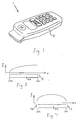
- Fig. 1 shows a mobile terminal 1, equipped with an antenna arrangement according to a first embodiment of the present invention.
- the mobile terminal 1 comprises a main casing 2, having an extended shape.
- Fig. 2 shows an exploded view of the mobile terminal in fig. 1. It comprises a screened compartment, or screening device SD, having a box-like shape.
- the screening device SD encloses radio electronic circuits REC, indicated with broken lines in fig. 2.
- a terminal chassis 4, having an extended shape and serving as a structural frame for the mobile terminal 1, is located within the main casing 2. As is described in SE0003951-1 the terminal chassis can serve as an end-fed antenna EA.
- the end-fed antenna EA presents a first end EA1 and a second end EA2.
- a counterpoise element 5 for the end-fed antenna EA is located near the first end EA1.
- the radio electronic circuits REC are connected between the end-fed antenna EA and the counterpoise 5, as illustrated by the broken lines L1 and L2, respectively.
- a tuning network TN is located Near the second end EA2 of the end-fed antenna EA.
- the tuning network TN is adapted to adjust the electrical length of the antenna so as to assume a value corresponding to a multiple of a half wave-length of the frequencies used.
- the tuning network TN comprises a conducting element CE and an inductor 6.
- the conductive element CE presents a relatively large capacitive reactance, but a small resistance.
- the conducting element CE consists of a metal plate, located at a small distance from the second end EA2.
- the conducting element CE can be held in place in the mobile terminal 1 by means of a holder, not shown, secured on the chassis 4, the holder being made of an insulating material.
- the counterpoise 5 can be secured against the screening compartment, or other suitable component of the mobile terminal 1, whereby the fastening means for the counterpoise element 5 is made out of a non-conductive material.
- the conducting element CE is shown as an essentially flat metal plate with an extended shape, being oriented transversely of the end-fed antenna EA.
- the length of the conducting element is substantially the same as the width of the mobile terminal 1.
- the metal plate is leaned in a direction towards the front side of the mobile terminal 1.
- the orientation of the conducting element CE in its transverse direction has no substantial effect on its functional efficiency.
- the metal plate could lean towards the back side of the mobile terminal 1. It could also be aligned with the end-fed antenna 4.
- the conducting element CE could be an extended metal plate having a curved cross section. It could also have the shape of a cylinder, having its axis transversely of the end-fed antenna EA.
- the inductance 6 connects the conducting element CE to the second end EA2 of the end-fed antenna EA, at which the inductance 6 is connected in series with the conducting element CE.
- Fig. 3 shows a diagram where the x-axis is parallel to the longitudinal axis of the end-fed antenna EA.
- the current distribution I is shown in the case no tuning network is used at the second end EA2 of the antenna EA.
- the current is zero at the second end EA2, but the maximum current occurs close to the first end EA1.
- the current distribution I is shown in the case a tuning network TN is used according to the invention at the second end EA2 of the antenna EA.
- the antenna EA has a higher impedance than in the case shown in fig. 3, so that it corresponds to the end-impedance of a half-wave antenna.
- the location of the maximum current is altered and it occurs at or close to the middle of the antenna EA. This results in a larger band-width compared to the arrangement shown in fig. 3.
- tuning network TN itself is not intended to provide radiation.
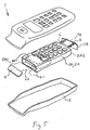
- Fig. 5 shows a second embodiment of the present invention.
- the screening device SD serves as the end-fed antenna EA, presenting a first end EA1 and a second end EA2.
- the connection from the radio electronic circuits REC to the screening device SD and the counterpoise 5 is represented by the broken lines L1 and L2, respectively.
- a tuning network TN is located, comprising a conducting element CE and two inductors 6.
- the conductive element CE presents similar features as the one described in connection to fig. 2 above, with the exception of its transverse orientation. Its plane is substantially perpendicular to the longitudinal axis of the end-fed antenna EA.
- the inductances 6 connects the conducting element CE to the second end EA2 of the end-fed antenna EA, at which the inductances 6 is connected in series with the conducting element CE.
- more than two inductances could be used.
- the object of having more than one inductance is to reduce the current concentration, thus reducing the local field strength, making the tuning of the electrical length of the antenna EA less sensitive to adjacent objects.
- the inductors be presented in the form of discrete inductors or a pattern on a printed circuit board.
- the figures 6-7 depict a mobile terminal 1 equipped with an antenna system according to a third embodiment of the present invention.
- a casing 2 encloses both a counterpoise element 5 and a screening device SD for radio electronic circuits REC.
- the screening device SD serves as an end-fed antenna EA, presenting a first end EA1 and a second end EA2.
- Both the counterpoise 5, near the first end EA1, and a conducting element CE of a tuning network TN, near the second end EA2 are in the form of metal strips, each extending in the transverse direction of the end-fed antenna EA.
- the cross section of each metal strip is oriented transversely of the longitudinal direction of the end-fed antenna EA.
- the casing of the mobile terminal may serve as an end-fed antenna fed against a counterpoise element, at which a tuning network according to the present invention is provided.
- Fig. 8-9 shows a mobile terminal equipped with an antenna system according to a fourth embodiment of the present invention.
- Radio electronic circuits REC are connected to a separate end-fed antenna EA with an extended shape and a counterpoise element 5, located near a first end EA1 of the antenna EA.
- the antenna shown is a tube with a round cross-section.
- the antenna can have any suitable form, being solid or tube-formed, presenting an extended shape with, for example square or rectangular cross-section.
- a tuning network is provided with a conducting element CE and an inductor 6 similar to what has been described above.
- the conductive element CE is oriented transversely of the antenna EA, and extends the full width of the inner space of the mobile terminal casing.
- the tuning network can be arranged to adjust the electrical length of the end-fed antenna individually for each band.
- a tuning network comprising a conducting element, for example in the form of a metal strip with an extended shape, arranged at an end of the antenna being opposite to the one at which a counterpoise element is located, in the same manner as described above.
- a circuit connecting the conduction element with the antenna is adapted to allow the antenna to obtain, for each band, an electrical length corresponding thereto.
- any of the antenna forms described above, whether it is separate, a chassis, screening or casing for the mobile terminal, can be arranged with any type of tuning network, whether it comprises one or more inductances or a circuit connecting a conducting element with the antenna.
Landscapes
- Engineering & Computer Science (AREA)
- Computer Networks & Wireless Communication (AREA)
- Support Of Aerials (AREA)
- Details Of Aerials (AREA)
Abstract
Description
- The present invention refers to an antenna system for a mobile terminal and a portable communications device, according to the preamble of claim 1 and 7, respectively.
- The patent application SE0003951-1, filed 2000-10-27, the subject matter of which forms the preamble of claim 1, discloses an antenna system for a mobile terminal, comprising an end-fed antenna, having an extended shape, and a counterpoise element, located near the first end of the end-fed antenna, the end-fed antenna being adapted to be fed, during transmission, against the counterpoise element.
- It is favorable for such an antenna having an electrical length corresponding approximately to the wavelength of the frequency, or frequencies, on which the antenna is intended to transmit or receive. Frequencies commonly used in mobile telephone communications are 900 and 1800 MHz. In mobile terminal technology, there has been, and continues to be, a trend towards decreasing the size of the terminals themselves. It is therefore difficult to meet requirements on the antenna's electrical length by adjusting its physical length, since this would result in the antenna being too large.
- In the art different approaches has been made to accomplish the desired electrical length of the antenna. It is known to use a tuning inductor and a capacitive hat on antennas to get resonance and to change the current distribution, (see ARRL Antenna Handbook). In WO9954956 extentions in the form of conductive patterns on a movable flap are used to obtain a larger antenna. These extensions form an essential part of the radiating structure.
- It is an object of the present invention to improve the efficiency of an antenna system for a mobile terminal.
- The object is met by an antenna system and a portable communications device, having the characterizing features of claim 1 and 7, respectively.
- Using a tuning network according to the invention makes it possible to achieve an antenna having an electrical length corresponding to multiples of half a wave-length of the frequency used, without having to utilize an antenna presenting dimensions being too large to meet demands on the terminal itself.
- Preferably the tuning network comprises a conducting element, with an extended shape and oriented in the transverse direction of the end-fed antenna. This will be favorable for the goal to reduce the size of the mobile terminal, since the tuning network, being oriented in the transverse direction of the antenna, and therefore the terminal itself, will have only a minor effect on the length of the mobile terminal.
- The invention will now be described in greater detail, with the aid of the accompanying drawings, on which
- fig. 1 shows a schematic perspective view of a mobile terminal, equipped with an antenna system according to a first embodiment of the present invention,
- fig. 2 shows a schematic exploded view of the mobile terminal from fig. 1,
- fig. 3 shows a diagram of a current distribution along an antenna,
- fig. 4 shows a diagram of a current distribution along an antenna,
- fig. 5 shows a schematic exploded view of a mobile terminal, equipped with an antenna system according to a second embodiment of the present invention,
- fig. 6 shows a schematic perspective view of a mobile terminal, equipped with an antenna system according to a third embodiment of the present invention,
- fig. 7 shows a schematic exploded view of the mobile terminal from fig. 6,
- fig. 8 shows a schematic perspective view of a mobile terminal, equipped with an antenna system according to a fourth embodiment of the present invention, and
- fig. 9 shows a schematic exploded view of the mobile terminal from fig. 8.
- Fig. 1 shows a mobile terminal 1, equipped with an antenna arrangement according to a first embodiment of the present invention. A wide array of different industrial designs for the mobile terminal are possible, and the appearance of the mobile terminal 1 in fig. 1 is exemplifying only. The mobile terminal 1 comprises a main casing 2, having an extended shape.
- Fig. 2 shows an exploded view of the mobile terminal in fig. 1. It comprises a screened compartment, or screening device SD, having a box-like shape. The screening device SD encloses radio electronic circuits REC, indicated with broken lines in fig. 2.
- A
terminal chassis 4, having an extended shape and serving as a structural frame for the mobile terminal 1, is located within the main casing 2. As is described in SE0003951-1 the terminal chassis can serve as an end-fed antenna EA. The end-fed antenna EA presents a first end EA1 and a second end EA2. Acounterpoise element 5 for the end-fed antenna EA is located near the first end EA1. The radio electronic circuits REC are connected between the end-fed antenna EA and thecounterpoise 5, as illustrated by the broken lines L1 and L2, respectively. - Near the second end EA2 of the end-fed antenna EA a tuning network TN is located. As will be described in more detail below, the tuning network TN is adapted to adjust the electrical length of the antenna so as to assume a value corresponding to a multiple of a half wave-length of the frequencies used.
- In the first embodiment of the invention the tuning network TN comprises a conducting element CE and an
inductor 6. The conductive element CE presents a relatively large capacitive reactance, but a small resistance. The conducting element CE consists of a metal plate, located at a small distance from the second end EA2. - The conducting element CE can be held in place in the mobile terminal 1 by means of a holder, not shown, secured on the
chassis 4, the holder being made of an insulating material. Alternatively thecounterpoise 5 can be secured against the screening compartment, or other suitable component of the mobile terminal 1, whereby the fastening means for thecounterpoise element 5 is made out of a non-conductive material. - In fig. 2 the conducting element CE is shown as an essentially flat metal plate with an extended shape, being oriented transversely of the end-fed antenna EA. Preferably, the length of the conducting element is substantially the same as the width of the mobile terminal 1.
- In fig. 2 the metal plate is leaned in a direction towards the front side of the mobile terminal 1. However, the orientation of the conducting element CE in its transverse direction has no substantial effect on its functional efficiency. As an alternative the metal plate could lean towards the back side of the mobile terminal 1. It could also be aligned with the end-fed
antenna 4. - Furthermore the conducting element CE could be an extended metal plate having a curved cross section. It could also have the shape of a cylinder, having its axis transversely of the end-fed antenna EA.
- The
inductance 6 connects the conducting element CE to the second end EA2 of the end-fed antenna EA, at which theinductance 6 is connected in series with the conducting element CE. - Fig. 3 shows a diagram where the x-axis is parallel to the longitudinal axis of the end-fed antenna EA. The current distribution I is shown in the case no tuning network is used at the second end EA2 of the antenna EA. The current is zero at the second end EA2, but the maximum current occurs close to the first end EA1.
- In fig. 4 the current distribution I is shown in the case a tuning network TN is used according to the invention at the second end EA2 of the antenna EA. The antenna EA has a higher impedance than in the case shown in fig. 3, so that it corresponds to the end-impedance of a half-wave antenna. The location of the maximum current is altered and it occurs at or close to the middle of the antenna EA. This results in a larger band-width compared to the arrangement shown in fig. 3.
- Obtaining the current distribution shown in fig. 4, leads to the electrical length of the antenna EA corresponding to half a wave-length at a frequency used. At half-wave-length resonance the impedance of the end-fed antenna is increased. As a result the impedance of the
counterpoise 5, although having the same absolute value, will be smaller in relation to the antenna impedance. The larger antenna moment achieved will result in making the bandwidth larger. It will also simplify matching the antenna EA, being fed against thecounterpoise 5. - It is important to note that the tuning network TN itself is not intended to provide radiation.
- Fig. 5 shows a second embodiment of the present invention. Here the screening device SD serves as the end-fed antenna EA, presenting a first end EA1 and a second end EA2. The connection from the radio electronic circuits REC to the screening device SD and the
counterpoise 5 is represented by the broken lines L1 and L2, respectively. - Near the second end EA2 of the end-fed antenna EA a tuning network TN is located, comprising a conducting element CE and two
inductors 6. The conductive element CE presents similar features as the one described in connection to fig. 2 above, with the exception of its transverse orientation. Its plane is substantially perpendicular to the longitudinal axis of the end-fed antenna EA. - The
inductances 6 connects the conducting element CE to the second end EA2 of the end-fed antenna EA, at which theinductances 6 is connected in series with the conducting element CE. Alternatively, more than two inductances could be used. The object of having more than one inductance is to reduce the current concentration, thus reducing the local field strength, making the tuning of the electrical length of the antenna EA less sensitive to adjacent objects. The inductors be presented in the form of discrete inductors or a pattern on a printed circuit board. - The figures 6-7 depict a mobile terminal 1 equipped with an antenna system according to a third embodiment of the present invention. A casing 2 encloses both a
counterpoise element 5 and a screening device SD for radio electronic circuits REC. As in fig. 5, the screening device SD serves as an end-fed antenna EA, presenting a first end EA1 and a second end EA2. Both thecounterpoise 5, near the first end EA1, and a conducting element CE of a tuning network TN, near the second end EA2, are in the form of metal strips, each extending in the transverse direction of the end-fed antenna EA. The cross section of each metal strip is oriented transversely of the longitudinal direction of the end-fed antenna EA. - As an alternative the casing of the mobile terminal, or part thereof, may serve as an end-fed antenna fed against a counterpoise element, at which a tuning network according to the present invention is provided.
- Fig. 8-9 shows a mobile terminal equipped with an antenna system according to a fourth embodiment of the present invention. Radio electronic circuits REC are connected to a separate end-fed antenna EA with an extended shape and a
counterpoise element 5, located near a first end EA1 of the antenna EA. The antenna shown is a tube with a round cross-section. However, the antenna can have any suitable form, being solid or tube-formed, presenting an extended shape with, for example square or rectangular cross-section. - Near a second end EA2 of the antenna EA a tuning network is provided with a conducting element CE and an
inductor 6 similar to what has been described above. Preferably the conductive element CE is oriented transversely of the antenna EA, and extends the full width of the inner space of the mobile terminal casing. - In the case the end-fed antenna is intended to transmit and receive signals on more than one frequency band, the tuning network can be arranged to adjust the electrical length of the end-fed antenna individually for each band. This can be achieved by a tuning network comprising a conducting element, for example in the form of a metal strip with an extended shape, arranged at an end of the antenna being opposite to the one at which a counterpoise element is located, in the same manner as described above. A circuit connecting the conduction element with the antenna is adapted to allow the antenna to obtain, for each band, an electrical length corresponding thereto.
- The features of the embodiments described above can be combined in any manner desired. Any of the antenna forms described above, whether it is separate, a chassis, screening or casing for the mobile terminal, can be arranged with any type of tuning network, whether it comprises one or more inductances or a circuit connecting a conducting element with the antenna.
Claims (9)
- An antenna system for a mobile terminal (1), comprising a casing (2), which accommodates radio electronic circuits (REC) and a screening device (SD) for the radio electronic circuits, the antenna system comprising an end-fed antenna (EA), having an extended shape, presenting a first end (EA1) and a second end (EA2) and being connected to the radio electronic circuits (REC), a counterpoise element (5), located near the first end (EA1) of the end-fed antenna (EA), the end-fed antenna being adapted to be fed against the counterpoise element (5) by the radio electronic circuits (REC), characterized in that a tuning network (TN) is located near the second end (EA2) of the end-fed antenna (EA).
- An antenna system according to claim 1, characterized in that the tuning network comprises a conducting element (CE), with an extended shape and oriented in the transverse direction of the end-fed antenna (EA).
- An antenna system according to claim 2, characterized in that the tuning network comprises at least one inductance element (6) connecting the conducting element (CE) to the second end (EA2) of the end-fed antenna (EA).
- An antenna system according to any of the preceding claims, characterized in that a terminal chassis (4) serves as the end-fed antenna (EA).
- An antenna system according to any of the preceding claims, characterized in that the screening device (SD) serves as the end-fed antenna (EA).
- An antenna system according to any of the preceding claims, characterized in that the casing (2) serves as the end-fed antenna (EA).
- A portable communications device comprising a casing (2), which accommodates radio electronic circuits (REC) and a screening device (SD) for the radio electronic circuits, and an end-fed antenna (EA), having an extended shape, presenting a first end (EA1) and a second end (EA2) and being connected to the radio electronic circuits (REC), a counterpoise element (5), located near the first end (EA1) of the end-fed antenna (EA), the end-fed antenna being adapted to be fed against the counterpoise element (5) by the radio electronic circuits (REC), characterized in that a tuning network (TN) is located near the second end (EA2) of the end-fed antenna (EA).
- A portable communications device according to claim 7, characterized in that the tuning network comprises a conducting element (CE), with an extended shape and oriented in the transverse direction of the end-fed antenna (EA).
- A portable communications device according to claim 8, characterized in that the tuning network comprises at least one inductance element (6) connecting the conducting element (CE) to the second end (EA2) of the end-fed antenna (EA).
Priority Applications (6)
| Application Number | Priority Date | Filing Date | Title |
|---|---|---|---|
| EP01109651A EP1251584B1 (en) | 2001-04-19 | 2001-04-19 | End-fed Antenna for a mobile terminal |
| AT01109651T ATE255283T1 (en) | 2001-04-19 | 2001-04-19 | END-FEEDED ANTENNA FOR MOBILE DEVICE |
| DE60101311T DE60101311D1 (en) | 2001-04-19 | 2001-04-19 | End-fed antenna for mobile devices |
| US10/475,151 US6950070B2 (en) | 2001-04-19 | 2002-04-17 | Arrangement for a mobile terminal |
| AU2002302543A AU2002302543A1 (en) | 2001-04-19 | 2002-04-17 | End-fed antenna for a mobile terminal |
| PCT/EP2002/004254 WO2002087010A2 (en) | 2001-04-19 | 2002-04-17 | End-fed antenna for a mobile terminal |
Applications Claiming Priority (1)
| Application Number | Priority Date | Filing Date | Title |
|---|---|---|---|
| EP01109651A EP1251584B1 (en) | 2001-04-19 | 2001-04-19 | End-fed Antenna for a mobile terminal |
Publications (2)
| Publication Number | Publication Date |
|---|---|
| EP1251584A1 true EP1251584A1 (en) | 2002-10-23 |
| EP1251584B1 EP1251584B1 (en) | 2003-11-26 |
Family
ID=8177178
Family Applications (1)
| Application Number | Title | Priority Date | Filing Date |
|---|---|---|---|
| EP01109651A Expired - Lifetime EP1251584B1 (en) | 2001-04-19 | 2001-04-19 | End-fed Antenna for a mobile terminal |
Country Status (3)
| Country | Link |
|---|---|
| EP (1) | EP1251584B1 (en) |
| AT (1) | ATE255283T1 (en) |
| DE (1) | DE60101311D1 (en) |
Cited By (1)
| Publication number | Priority date | Publication date | Assignee | Title |
|---|---|---|---|---|
| CN101999191B (en) * | 2008-04-17 | 2013-10-30 | 索尼爱立信移动通讯有限公司 | Antenna device |
Citations (3)
| Publication number | Priority date | Publication date | Assignee | Title |
|---|---|---|---|---|
| US4491843A (en) * | 1981-01-23 | 1985-01-01 | Thomson-Csf | Portable receiver with housing serving as a dipole antenna |
| US5701128A (en) * | 1995-03-03 | 1997-12-23 | Murata Manufacturing Co., Ltd. | Antenna-integrated strip line cable |
| US6107967A (en) * | 1998-07-28 | 2000-08-22 | Wireless Access, Inc. | Billboard antenna |
-
2001
- 2001-04-19 AT AT01109651T patent/ATE255283T1/en not_active IP Right Cessation
- 2001-04-19 DE DE60101311T patent/DE60101311D1/en not_active Expired - Lifetime
- 2001-04-19 EP EP01109651A patent/EP1251584B1/en not_active Expired - Lifetime
Patent Citations (3)
| Publication number | Priority date | Publication date | Assignee | Title |
|---|---|---|---|---|
| US4491843A (en) * | 1981-01-23 | 1985-01-01 | Thomson-Csf | Portable receiver with housing serving as a dipole antenna |
| US5701128A (en) * | 1995-03-03 | 1997-12-23 | Murata Manufacturing Co., Ltd. | Antenna-integrated strip line cable |
| US6107967A (en) * | 1998-07-28 | 2000-08-22 | Wireless Access, Inc. | Billboard antenna |
Cited By (1)
| Publication number | Priority date | Publication date | Assignee | Title |
|---|---|---|---|---|
| CN101999191B (en) * | 2008-04-17 | 2013-10-30 | 索尼爱立信移动通讯有限公司 | Antenna device |
Also Published As
| Publication number | Publication date |
|---|---|
| DE60101311D1 (en) | 2004-01-08 |
| EP1251584B1 (en) | 2003-11-26 |
| ATE255283T1 (en) | 2003-12-15 |
Similar Documents
| Publication | Publication Date | Title |
|---|---|---|
| US6580397B2 (en) | Arrangement for a mobile terminal | |
| US6218992B1 (en) | Compact, broadband inverted-F antennas with conductive elements and wireless communicators incorporating same | |
| US7916086B2 (en) | Antenna component and methods | |
| EP3767742B1 (en) | Antenna device and mobile terminal | |
| JP4423809B2 (en) | Double resonance antenna | |
| US6593897B1 (en) | Wireless GPS apparatus with integral antenna device | |
| US6229487B1 (en) | Inverted-F antennas having non-linear conductive elements and wireless communicators incorporating the same | |
| EP1315238A2 (en) | Enhancing electrical isolation between two antennas of a radio device | |
| CN111029729A (en) | Antenna assembly and electronic equipment | |
| JPH05500889A (en) | Transmitting and/or receiving devices for portable devices | |
| JP2003504902A (en) | Integrated dual band antenna | |
| US6873296B2 (en) | Multi-band vehicular blade antenna | |
| US20020190913A1 (en) | Multiple band split ground plane antenna assembly | |
| US6567047B2 (en) | Multi-band in-series antenna assembly | |
| JPH11340726A (en) | Antenna device | |
| CN201060933Y (en) | Balanced type dual-branch plane inverse F type antenna | |
| CN109841954B (en) | Antenna structure and wireless communication device with same | |
| US6618015B2 (en) | Antenna for use with radio device | |
| EP1251584B1 (en) | End-fed Antenna for a mobile terminal | |
| US6950070B2 (en) | Arrangement for a mobile terminal | |
| US6968203B2 (en) | Device for mobile terminal | |
| KR100861865B1 (en) | Wireless terminal | |
| CN119070001A (en) | Electronic devices | |
| US7149540B2 (en) | Antenna | |
| CN119381766B (en) | electronic devices |
Legal Events
| Date | Code | Title | Description |
|---|---|---|---|
| PUAI | Public reference made under article 153(3) epc to a published international application that has entered the european phase |
Free format text: ORIGINAL CODE: 0009012 |
|
| AK | Designated contracting states |
Kind code of ref document: A1 Designated state(s): AT BE CH CY DE DK ES FI FR GB GR IE IT LI LU MC NL PT SE TR |
|
| AX | Request for extension of the european patent |
Free format text: AL;LT;LV;MK;RO;SI |
|
| GRAH | Despatch of communication of intention to grant a patent |
Free format text: ORIGINAL CODE: EPIDOS IGRA |
|
| 17P | Request for examination filed |
Effective date: 20030410 |
|
| AKX | Designation fees paid |
Designated state(s): AT BE CH CY DE DK ES FI FR GB GR IE IT LI LU MC NL PT SE TR |
|
| GRAS | Grant fee paid |
Free format text: ORIGINAL CODE: EPIDOSNIGR3 |
|
| GRAA | (expected) grant |
Free format text: ORIGINAL CODE: 0009210 |
|
| AK | Designated contracting states |
Kind code of ref document: B1 Designated state(s): AT BE CH CY DE DK ES FI FR GB GR IE IT LI LU MC NL PT SE TR |
|
| PG25 | Lapsed in a contracting state [announced via postgrant information from national office to epo] |
Ref country code: IT Free format text: LAPSE BECAUSE OF FAILURE TO SUBMIT A TRANSLATION OF THE DESCRIPTION OR TO PAY THE FEE WITHIN THE PRESCRIBED TIME-LIMIT;WARNING: LAPSES OF ITALIAN PATENTS WITH EFFECTIVE DATE BEFORE 2007 MAY HAVE OCCURRED AT ANY TIME BEFORE 2007. THE CORRECT EFFECTIVE DATE MAY BE DIFFERENT FROM THE ONE RECORDED. Effective date: 20031126 Ref country code: TR Free format text: LAPSE BECAUSE OF FAILURE TO SUBMIT A TRANSLATION OF THE DESCRIPTION OR TO PAY THE FEE WITHIN THE PRESCRIBED TIME-LIMIT Effective date: 20031126 Ref country code: NL Free format text: LAPSE BECAUSE OF FAILURE TO SUBMIT A TRANSLATION OF THE DESCRIPTION OR TO PAY THE FEE WITHIN THE PRESCRIBED TIME-LIMIT Effective date: 20031126 Ref country code: FR Free format text: LAPSE BECAUSE OF FAILURE TO SUBMIT A TRANSLATION OF THE DESCRIPTION OR TO PAY THE FEE WITHIN THE PRESCRIBED TIME-LIMIT Effective date: 20031126 Ref country code: LI Free format text: LAPSE BECAUSE OF FAILURE TO SUBMIT A TRANSLATION OF THE DESCRIPTION OR TO PAY THE FEE WITHIN THE PRESCRIBED TIME-LIMIT Effective date: 20031126 Ref country code: FI Free format text: LAPSE BECAUSE OF FAILURE TO SUBMIT A TRANSLATION OF THE DESCRIPTION OR TO PAY THE FEE WITHIN THE PRESCRIBED TIME-LIMIT Effective date: 20031126 Ref country code: BE Free format text: LAPSE BECAUSE OF FAILURE TO SUBMIT A TRANSLATION OF THE DESCRIPTION OR TO PAY THE FEE WITHIN THE PRESCRIBED TIME-LIMIT Effective date: 20031126 Ref country code: CY Free format text: LAPSE BECAUSE OF FAILURE TO SUBMIT A TRANSLATION OF THE DESCRIPTION OR TO PAY THE FEE WITHIN THE PRESCRIBED TIME-LIMIT Effective date: 20031126 Ref country code: AT Free format text: LAPSE BECAUSE OF FAILURE TO SUBMIT A TRANSLATION OF THE DESCRIPTION OR TO PAY THE FEE WITHIN THE PRESCRIBED TIME-LIMIT Effective date: 20031126 Ref country code: CH Free format text: LAPSE BECAUSE OF FAILURE TO SUBMIT A TRANSLATION OF THE DESCRIPTION OR TO PAY THE FEE WITHIN THE PRESCRIBED TIME-LIMIT Effective date: 20031126 |
|
| REG | Reference to a national code |
Ref country code: GB Ref legal event code: FG4D |
|
| REG | Reference to a national code |
Ref country code: CH Ref legal event code: EP |
|
| REF | Corresponds to: |
Ref document number: 60101311 Country of ref document: DE Date of ref document: 20040108 Kind code of ref document: P |
|
| REG | Reference to a national code |
Ref country code: IE Ref legal event code: FG4D |
|
| PG25 | Lapsed in a contracting state [announced via postgrant information from national office to epo] |
Ref country code: GR Free format text: LAPSE BECAUSE OF FAILURE TO SUBMIT A TRANSLATION OF THE DESCRIPTION OR TO PAY THE FEE WITHIN THE PRESCRIBED TIME-LIMIT Effective date: 20040226 Ref country code: DK Free format text: LAPSE BECAUSE OF FAILURE TO SUBMIT A TRANSLATION OF THE DESCRIPTION OR TO PAY THE FEE WITHIN THE PRESCRIBED TIME-LIMIT Effective date: 20040226 Ref country code: SE Free format text: LAPSE BECAUSE OF FAILURE TO SUBMIT A TRANSLATION OF THE DESCRIPTION OR TO PAY THE FEE WITHIN THE PRESCRIBED TIME-LIMIT Effective date: 20040226 |
|
| PG25 | Lapsed in a contracting state [announced via postgrant information from national office to epo] |
Ref country code: DE Free format text: LAPSE BECAUSE OF FAILURE TO SUBMIT A TRANSLATION OF THE DESCRIPTION OR TO PAY THE FEE WITHIN THE PRESCRIBED TIME-LIMIT Effective date: 20040227 |
|
| PG25 | Lapsed in a contracting state [announced via postgrant information from national office to epo] |
Ref country code: ES Free format text: LAPSE BECAUSE OF FAILURE TO SUBMIT A TRANSLATION OF THE DESCRIPTION OR TO PAY THE FEE WITHIN THE PRESCRIBED TIME-LIMIT Effective date: 20040309 |
|
| PG25 | Lapsed in a contracting state [announced via postgrant information from national office to epo] |
Ref country code: IE Free format text: LAPSE BECAUSE OF NON-PAYMENT OF DUE FEES Effective date: 20040419 Ref country code: LU Free format text: LAPSE BECAUSE OF NON-PAYMENT OF DUE FEES Effective date: 20040419 |
|
| RAP2 | Party data changed (patent owner data changed or rights of a patent transferred) |
Owner name: TELEFONAKTIEBOLAGET LM ERICSSON (PUBL) |
|
| PG25 | Lapsed in a contracting state [announced via postgrant information from national office to epo] |
Ref country code: MC Free format text: LAPSE BECAUSE OF NON-PAYMENT OF DUE FEES Effective date: 20040430 |
|
| NLV1 | Nl: lapsed or annulled due to failure to fulfill the requirements of art. 29p and 29m of the patents act | ||
| REG | Reference to a national code |
Ref country code: CH Ref legal event code: PL |
|
| PLBE | No opposition filed within time limit |
Free format text: ORIGINAL CODE: 0009261 |
|
| STAA | Information on the status of an ep patent application or granted ep patent |
Free format text: STATUS: NO OPPOSITION FILED WITHIN TIME LIMIT |
|
| 26N | No opposition filed |
Effective date: 20040827 |
|
| EN | Fr: translation not filed | ||
| REG | Reference to a national code |
Ref country code: IE Ref legal event code: MM4A |
|
| PG25 | Lapsed in a contracting state [announced via postgrant information from national office to epo] |
Ref country code: PT Free format text: LAPSE BECAUSE OF NON-PAYMENT OF DUE FEES Effective date: 20040426 |
|
| PGFP | Annual fee paid to national office [announced via postgrant information from national office to epo] |
Ref country code: GB Payment date: 20180427 Year of fee payment: 18 |
|
| GBPC | Gb: european patent ceased through non-payment of renewal fee |
Effective date: 20190419 |
|
| PG25 | Lapsed in a contracting state [announced via postgrant information from national office to epo] |
Ref country code: GB Free format text: LAPSE BECAUSE OF NON-PAYMENT OF DUE FEES Effective date: 20190419 |