EP1251528A2 - Surge protection device - Google Patents
Surge protection device Download PDFInfo
- Publication number
- EP1251528A2 EP1251528A2 EP02008565A EP02008565A EP1251528A2 EP 1251528 A2 EP1251528 A2 EP 1251528A2 EP 02008565 A EP02008565 A EP 02008565A EP 02008565 A EP02008565 A EP 02008565A EP 1251528 A2 EP1251528 A2 EP 1251528A2
- Authority
- EP
- European Patent Office
- Prior art keywords
- fuse
- voltage
- spring
- trace
- surge protection
- Prior art date
- Legal status (The legal status is an assumption and is not a legal conclusion. Google has not performed a legal analysis and makes no representation as to the accuracy of the status listed.)
- Withdrawn
Links
Images





Classifications
-
- H—ELECTRICITY
- H01—ELECTRIC ELEMENTS
- H01H—ELECTRIC SWITCHES; RELAYS; SELECTORS; EMERGENCY PROTECTIVE DEVICES
- H01H85/00—Protective devices in which the current flows through a part of fusible material and this current is interrupted by displacement of the fusible material when this current becomes excessive
- H01H85/02—Details
- H01H85/44—Structural association with a spark-gap arrester
-
- H—ELECTRICITY
- H01—ELECTRIC ELEMENTS
- H01C—RESISTORS
- H01C7/00—Non-adjustable resistors formed as one or more layers or coatings; Non-adjustable resistors made from powdered conducting material or powdered semi-conducting material with or without insulating material
- H01C7/10—Non-adjustable resistors formed as one or more layers or coatings; Non-adjustable resistors made from powdered conducting material or powdered semi-conducting material with or without insulating material voltage responsive, i.e. varistors
- H01C7/12—Overvoltage protection resistors; Arresters
-
- H—ELECTRICITY
- H01—ELECTRIC ELEMENTS
- H01H—ELECTRIC SWITCHES; RELAYS; SELECTORS; EMERGENCY PROTECTIVE DEVICES
- H01H37/00—Thermally-actuated switches
- H01H37/02—Details
- H01H37/04—Bases; Housings; Mountings
- H01H2037/046—Bases; Housings; Mountings being soldered on the printed circuit to be protected
-
- H—ELECTRICITY
- H01—ELECTRIC ELEMENTS
- H01H—ELECTRIC SWITCHES; RELAYS; SELECTORS; EMERGENCY PROTECTIVE DEVICES
- H01H37/00—Thermally-actuated switches
- H01H37/74—Switches in which only the opening movement or only the closing movement of a contact is effected by heating or cooling
- H01H37/76—Contact member actuated by melting of fusible material, actuated due to burning of combustible material or due to explosion of explosive material
- H01H37/761—Contact member actuated by melting of fusible material, actuated due to burning of combustible material or due to explosion of explosive material with a fusible element forming part of the switched circuit
- H01H2037/762—Contact member actuated by melting of fusible material, actuated due to burning of combustible material or due to explosion of explosive material with a fusible element forming part of the switched circuit using a spring for opening the circuit when the fusible element melts
- H01H2037/763—Contact member actuated by melting of fusible material, actuated due to burning of combustible material or due to explosion of explosive material with a fusible element forming part of the switched circuit using a spring for opening the circuit when the fusible element melts the spring being a blade spring
-
- H—ELECTRICITY
- H01—ELECTRIC ELEMENTS
- H01H—ELECTRIC SWITCHES; RELAYS; SELECTORS; EMERGENCY PROTECTIVE DEVICES
- H01H37/00—Thermally-actuated switches
- H01H37/74—Switches in which only the opening movement or only the closing movement of a contact is effected by heating or cooling
- H01H37/76—Contact member actuated by melting of fusible material, actuated due to burning of combustible material or due to explosion of explosive material
- H01H37/761—Contact member actuated by melting of fusible material, actuated due to burning of combustible material or due to explosion of explosive material with a fusible element forming part of the switched circuit
-
- H—ELECTRICITY
- H01—ELECTRIC ELEMENTS
- H01H—ELECTRIC SWITCHES; RELAYS; SELECTORS; EMERGENCY PROTECTIVE DEVICES
- H01H85/00—Protective devices in which the current flows through a part of fusible material and this current is interrupted by displacement of the fusible material when this current becomes excessive
- H01H85/02—Details
- H01H85/46—Circuit arrangements not adapted to a particular application of the protective device
- H01H85/463—Circuit arrangements not adapted to a particular application of the protective device with printed circuit fuse
-
- H—ELECTRICITY
- H05—ELECTRIC TECHNIQUES NOT OTHERWISE PROVIDED FOR
- H05K—PRINTED CIRCUITS; CASINGS OR CONSTRUCTIONAL DETAILS OF ELECTRIC APPARATUS; MANUFACTURE OF ASSEMBLAGES OF ELECTRICAL COMPONENTS
- H05K1/00—Printed circuits
- H05K1/02—Details
- H05K1/0201—Thermal arrangements, e.g. for cooling, heating or preventing overheating
-
- H—ELECTRICITY
- H05—ELECTRIC TECHNIQUES NOT OTHERWISE PROVIDED FOR
- H05K—PRINTED CIRCUITS; CASINGS OR CONSTRUCTIONAL DETAILS OF ELECTRIC APPARATUS; MANUFACTURE OF ASSEMBLAGES OF ELECTRICAL COMPONENTS
- H05K3/00—Apparatus or processes for manufacturing printed circuits
- H05K3/30—Assembling printed circuits with electric components, e.g. with resistors
- H05K3/32—Assembling printed circuits with electric components, e.g. with resistors electrically connecting electric components or wires to printed circuits
- H05K3/34—Assembling printed circuits with electric components, e.g. with resistors electrically connecting electric components or wires to printed circuits by soldering
- H05K3/341—Surface mounted components
Definitions
- This invention relates generally to apparatus for protecting a facility and its loads from surges and other disturbances in supply voltage and, more particularly, to a surge protection device such as, for example, an alternating current (AC) surge protective device (SPD) for such loads.
- a surge protection device such as, for example, an alternating current (AC) surge protective device (SPD) for such loads.
- the invention also relates to devices and methods for manufacturing a thermal fuse spring.
- series protection a high impedance is used in series with the load during a surge to block or limit surge current.
- parallel protection the surge current is diverted with a low impedance shunt. The present invention provides parallel protection.
- MOVs metal oxide varistors
- zener diodes zener diodes
- silicon avalanche diodes If used alone to provide parallel protection, an MOV, for example, must have a clamping voltage that is above the nominal supply voltage in order that its maximum continuous operating voltage (MCOV) is above the nominal supply voltage.
- CMOS complementary metal oxide varistors
- MCOV continuous operating voltage
- These devices normally have a high impedance and switch to a low impedance when a surge in the supply voltage exceeds the breakdown voltage of the gas in the case of the gas discharge tube, or is high enough to activate a trigger circuit to turn the thyristor on.
- FIG. 1 shows a prior proposal for a surge protection device (SPD) circuit in which thermal disconnection of a failing MOV is used.
- the SPD 2 includes a conventional overcurrent fuse 4, three MOVs 6,8,10, and two thermal cut-off (TCO) devices 12,14.
- the SPD 2 is employed in a conventional AC power circuit 16 including a power input 18 having phase 20, neutral 22, and ground 24 connections, and a power output 26 having phase 28, neutral 30, and ground 32 connections.
- a circuit breaker or fuse is typically employed upstream from the SPD 2, in order to protect against a fatal failure of the SPD.
- a circuit breaker or switch 34 is electrically connected in series between the phase input connection 20 and the phase output connection 28.
- the reaction time is relatively long.
- the metal cases of the TCOs 12,14 are warmed by heat generated by the MOVs 6,8,10, with heat transfer from MOV to TCO being provided by radiation through the air. Because air and the MOV coatings are thermal isolators, it takes time for the TCOs to disconnect the MOVs during an abnormal condition of the SPD 2.
- the surge current rating of the TCOs 12,14 is also a limiting factor.
- One TCO is typically suitable for only one MOV.
- the major disadvantage is cost, since one TCO costs several times more than the corresponding MOV, which is to be protected. In order to improve the cost ratio, it is known to employ a combination of a plural MOVs connected in parallel in combination with a single TCO. However, in that case, the TCO does not have a surge current capability equivalent to that of the parallel connected MOVs.
- FIG. 2 shows a SPD 36 including a plurality of MOVs 38, which are electrically interconnected in parallel.
- Each of the MOVs 38 is electrically connected in series with a corresponding one of the fuses 40 in order to provide individual overcurrent protection.
- Each of the fuses 40 is intended to open circuit when the corresponding MOV 38 fails and electrical current flowing through that fuse exceeds the current rating thereof.
- that current rating might not be suitable to prevent fire on the corresponding MOV 38 in the event that the surge rating of the corresponding fuse 40 exceeds the surge current rating of that MOV.
- the SPD 36 and perhaps the protected load (not shown) might be subject to substantial damage from fire and/or explosion. Degradation of MOVs might occur due to various reasons, which might lead to such a catastrophic failure of the SPD. Although this rarely happens, the end user must be protected.
- a relatively high surge-rated SPD usually has plural MOVs connected in parallel in order to share surge currents.
- MOVs A failure of MOVs is extremely rare, but it is catastrophic when it occurs. The reasons for such failures are most often due to abnormal overvoltage (e.g ., up to about 200% of nominal voltage) or surges.
- fuse trace copper conductor on a printed circuit board (PCB) in series with a single MOV, or overcurrent protection per phase (e.g., a standard RK5 fuse, fuse resistor, block fuse, TCO, thermal fuse, surge fuse).
- overcurrent protection per phase e.g., a standard RK5 fuse, fuse resistor, block fuse, TCO, thermal fuse, surge fuse.
- fuse traces are functional only up to certain levels of surge current.
- known fuse traces cannot handle relatively higher surges (e.g ., higher than about 6.5 kA) and still remain suitable for disconnecting a failing MOV at a fault condition (e.g., a fault current of less than about 10 A). This presents two opposite requirements for fuse trace design.
- a fuse trace in order to handle relatively higher surge currents, a fuse trace must have a cross-sectional area which is as large as possible. Second, in order to disconnect a failing MOV in a relatively short time, a fuse trace must have as small of a cross-sectional area as possible. Overcurrent protection, alone, is insufficient to meet these two requirements.
- MOV surge ratings are increasing to relatively higher levels. For example, several years ago, 20 mm MOVs were rated up to about 6.5 kA (with a 8 x 20 ⁇ s standard waveform). Today, 20 mm MOVs are rated up to about 18 kA surge current.
- U.S. Patent No. 4,862,134 discloses an electrical fuse including a fusible conductor welded or bonded onto separated contact surfaces.
- U.S. Patent No. 6,067,216 discloses a circuit arrangement for protecting an electrical component from an undesirable electrical potential.
- the circuit arrangement includes a protective element, such as a diode, varistor or thyristor, in parallel with the electrical component.
- a protective element such as a diode, varistor or thyristor
- the protective element such as a surface mounted diode
- the solder mounting the diode becomes liquefied as a result of heating of the diode.
- a divided pair of soldering pads is employed for one of the connections to the diode, which results in a more rapid rise of temperature than on an undivided soldering pad for the other connection to the diode.
- U.S. Patent Nos. 5,600,295 and 5,896,080 disclose thermal fuses for circuit substrates and printed circuit boards.
- fusing in SPDs can be internal or external (e.g. , inside the SPD enclosure, or circuit breakers and fuses outside the SPD enclosure).
- a surge protection device includes plural voltage clamping means, such as MOVs, accompanied by a thermal fuse spring and a fuse trace.
- MOV pre-fault
- MOV fault current MOV fault current rating
- MOV surge current rating for safe disconnection of the MOVs under certain failure conditions, such as overvoltage or surge.
- a surge protection device for a load supplied with at least one voltage from a power source comprises: at least two terminals adapted to receive the voltage; and a plurality of surge protection circuits, each of the surge protection circuits comprising: a thermal fuse spring, at least one means for clamping a voltage, and at least one fuse trace, each one of the at least one fuse trace corresponding to one of the at least one means for clamping a voltage, with the thermal fuse spring, one of the at least one fuse trace and a corresponding one of the at least one means for clamping a voltage being electrically interconnected in series between the terminals, in order to form at least one series electrical connection between the terminals, with the thermal fuse spring being adapted to disconnect the at least one series electrical connection between the terminals under first fault conditions of the at least one means for clamping a voltage, the first fault conditions including a first current through one of the at least one means for clamping a voltage for a first duration, with the thermal fuse spring and the at least one fuse trace being adapted to cooperative
- the at least one means for clamping a voltage may be a metal oxide varistor having a catastrophic failure state under overvoltage conditions
- the at least one fuse trace may be a fuse trace.
- Each of the thermal fuse spring and the fuse trace has a time versus current characteristic which is coordinated with the catastrophic failure state of the metal oxide varistor in order to disconnect the metal oxide varistor from the voltage under the overvoltage conditions.
- At least one of the thermal fuse spring and the fuse trace disconnects the metal oxide varistor from the voltage in order to prevent the catastrophic failure state under the overvoltage conditions.
- the surge protection circuits may include a printed circuit board.
- the fuse trace may include a first conductive trace on the printed circuit board, a conductive through hole in the printed circuit board, and a second conductive trace on the printed circuit board, with the first conductive trace being electrically connected to the input of the fuse trace and to the conductive through hole, and with the second conductive trace being electrically connected to the conductive through hole and to the output of the fuse trace.
- the conductive through hole of the fuse trace is filled with solder, in order to shorten a disconnection time of the fuse trace during an overcurrent condition.
- solder may have a melting temperature of between about 175 degrees C and about 250 degrees C.
- the surge protection circuits may include a printed circuit board having a first conductor, which is electrically connected to one of the terminals, and a second conductor, which is electrically interconnected with the input of the fuse trace.
- the first spring member of the thermal fuse spring may be soldered to the first conductor of the printed circuit board and the second spring member of the thermal fuse spring may be stretched away from the first spring member and soldered to the second conductor of the printed circuit board.
- the first and second spring members of the thermal fuse spring are each soldered to the printed circuit board with a solder having a melting temperature of about 80 degrees C to about 120 degrees C.
- a method of manufacturing a thermal fuse spring comprises: cutting a flexible conductive material to form a base and a plurality of fingers; bending the base and the fingers to form a plurality of thermal fuse spring elements having a common base and a plurality of independent leg elements; stretching each of the leg elements away from the common base; positioning the common base and the stretched leg elements on a printed circuit board; and soldering the common base and the stretched leg elements to the printed circuit board.
- a stretcher device is for use in mounting at least one thermal fuse spring on a printed circuit board.
- the thermal fuse spring includes a spring member having a pair of legs each of which has a hooked foot member.
- the stretcher device comprises: a base including first and second ends, first and second sides, and an elongated opening in the base; a first alignment member affixed to the first end of the base; a second alignment member affixed to the second end of the base; a first elongated arcuate member affixed to the first side of the base; and a second elongated arcuate member affixed to the second side of the base, with the opening of the base adapted to receive the spring member of the thermal fuse spring, and with the first and second elongated arcuate members adapted to hold the hooked foot members of the thermal fuse spring with the legs thereof being stretched thereapart for engagement with the printed circuit board.
- a surge protection device for a load supplied with a voltage from a power source comprises: a plurality of terminals adapted to receive the voltage; a printed circuit board; and a plurality of surge protection circuits, each of the surge protection circuits comprising: a thermal fuse spring on the printed circuit board, means for clamping a voltage, a fuse trace electrically interconnected in series with the thermal fuse spring and the means for clamping a voltage between the terminals, in order to form a series electrical connection between the terminals, the fuse trace including at least one conductive trace on the printed circuit board and also including a conductive through hole in the printed circuit board and electrically connected to the at least one conductive trace, and with the thermal fuse spring being adapted to disconnect the series electrical connection between the terminals under first fault conditions of the means for clamping a voltage, and with the thermal fuse spring and the fuse trace being adapted to cooperatively disconnect the series electrical connection between the terminals under second fault conditions of the means for clamping a voltage.
- the present invention deals with internal fuses for SPDs and provides a combination of thermal disconnection and overcurrent protection, in which pre-fault current, fault current and surge current are coordinated through all three SPD components (e.g. , MOV, thermal fuse spring (TFS), fuse trace (FT)).
- the TFS and the FT together protect the MOV in the event of fault conditions.
- the FT increases the available interruptive current (AIC) (i.e., maximum fault current) rating of the SPD device.
- Figure 3 shows plots of abnormal MOV overvoltage and corresponding MOV current during a limited current test of a SPD.
- three MOVs are connected in parallel and initially have a nominal leakage current 39 and a nominal system voltage 41. Then, the MOVs are exposed to twice that nominal system voltage. In the pre-fault condition 42, all three MOVs clamp the voltage for several cycles.
- the exemplary voltage peak of the sine-like waveform is about 100 V and the current peak is about 2 A. Then, beginning at time 0.0 s for the first fault condition 44, one of the MOVs fails and conducts about 10 A peak current before disconnection by a fuse.
- the remaining MOVs clamp the voltage at about 100 Vpeak for several cycles with the current peak being less than 2 A.
- the second fault condition 48 one of remaining MOVs heats up and fails with limited current at about 10 Apeak for several cycles before it is disconnected by a fuse.
- the remaining MOV starts to clamp in the third pre-fault condition 50 and then fails in the third fault condition 52 in the same way.
- the cause of fire in SPDs is improper fuse design.
- the overcurrent fuse for individual MOV protection must meet two requirements. First, an overcurrent fuse must open before the protected MOV catches fire. Second, the fuse must conduct (let through) surge current, which is at least as great as the surge rating of the corresponding MOV.
- the combination of the TFS and the FT perform disconnection of the MOV during fault conditions. Furthermore, at the same time, this combination is designed to conduct normal current without significant heat generation. During normal conditions, the TFS and FT preferably do not exceed thermal or mechanical stress, which would otherwise change the proper functioning of these components. This is accomplished by employing leakage current coordination during the design of these components. Hence, at relatively low fault current conditions (e.g., with a relatively high source impedance), when the short circuit current is limited ( e.g ., to several amps), then the TFS should react first ( i.e., faster then the FT) and disconnect a shorted MOV.
- relatively low fault current conditions e.g., with a relatively high source impedance
- the short circuit current is limited ( e.g ., to several amps)
- the TFS should react first ( i.e., faster then the FT) and disconnect a shorted MOV.
- the FT should preferably open before the TFS and disconnect the shorted MOV.
- the adjacent TFS disconnects as well.
- Figure 4 shows two log-log plots 54 and 56 which provide coordinated thermal fusing and overcurrent disconnection, respectively, for a SPD including a combination of a MOV, a thermal fuse spring (TFS) and a fuse trace with solder hole (FTWSH) (as discussed below in connection with Figures 5A-5B) in accordance with an embodiment of the present invention.
- the plot 54 shows log (time (t)) versus log (current (I)) for the combination of the MOV and TFS, while the plot 56 shows log (t) versus log (I) for the FTWSH.
- a conduction region 58 is shown toward the bottom left of the plots 54,56, while a disconnection region 60 is shown toward the upper right of such plots.
- both of the TFS and the fuse trace (FT) are designed to withstand relatively very high surges ( i.e., in a relatively very short period of time).
- the thermal fuse spring (TFS) is heated by the MOV and is capable of disconnecting the MOV at fault conditions measured in a relatively low current range (e.g., from about point 62 to about point 65 of plot 54 of Figure 4).
- the FT is capable of disconnecting the MOV at fault conditions in a relatively higher current range (e.g., from about point 65 to about point 68 on plot 56 of Figure 4).
- the FT alone is insufficient to prevent catastrophic failure of the MOV.
- the TFS disconnects a failing MOV.
- the FT disconnects the MOV.
- the FT opens the MOV faster than does the TFS. In this manner, the FT improves the AIC rating of the SPD.
- the TFS and FT cooperatively provide coordinated disconnection of the MOV from the power source under overvoltage (fault) conditions.
- the exemplary TFS, FTWSH and MOV combination provides suitable disconnection for a wide range of fault currents. Furthermore, it maintains proper surge current ratings, which is termed "surge current coordination".
- a SPD 70 includes an exemplary printed circuit board (PCB) 72 and the combination of a MOV 74, a thermal fuse spring (TFS) 76 and a fuse trace with solder hole (FTWSH) 78 in accordance with the present invention.
- the MOV 74 includes leads 80,82, which are inserted in respective through holes 84,86 of the PCB 72.
- the FTWSH 78 includes PCB copper traces 88,90 and through hole 92.
- the through hole 92 is positioned between the MOV lead 80 and the TFS foot 104.
- the traces 88,90 are unplated.
- the through holes 84,86,92 are filled with solder, such as conventional solder 94 in the through hole 84 and conventional solder 96 (e.g ., having a melting temperature of between about 175°C and about 250°C) in the through hole 92.
- solder such as conventional solder 94 in the through hole 84 and conventional solder 96 (e.g ., having a melting temperature of between about 175°C and about 250°C) in the through hole 92.
- solder 96 e.g ., having a melting temperature of between about 175°C and about 250°C
- the solder 96 is advantageously employed to shorten the disconnection time of the FTWSH 78 under overcurrent conditions by first melting and, then, hastening the disconnection ( e.g., by burning) of one or both of the FTWSH PCB copper traces 88,90.
- a 250°C solder melting temperature promotes a relatively longer disconnection time, since greater MOV leakage current is required to melt the solder 96 and burn one or both of the traces 88,90.
- a 175°C solder melting temperature for example, promotes a relatively shorter disconnection time, since relatively less MOV leakage current is required to melt the solder 96 and burn one or both of the traces 88,90.
- the burning of the traces 88,90 includes two components: (1) melting of the copper trace(s); and (2) arcing of those copper traces.
- a surge may not burn the traces and may, instead, be clamped by the MOV.
- a persistent current may provide sufficient energy to both melt and cause arcing of the copper traces, thereby leading to disconnection of the MOV.
- the TFS 76 is placed on the PCB 72 during a surface mounting (re-flow) process.
- a fusible alloy such as a suitably low temperature solder, shown at 100 and 102, is employed at the feet 104,106 of the TFS 76, in order to hold the TFS 76 in a normal stretched position.
- a series electrical connection is established from PCB copper trace 108, to solder 102, to the foot 106 of the TFS 76 and through such TFS to the foot 104, to the solder 100, to the copper trace 88, to the through hole 92, to the copper trace 90, to the through hole 84, to the MOV lead 80 and, thus, to the MOV 74.
- the leakage current through the TFS 76, FTWSH 78 and MOV 74 is in the order of several ⁇ A. There is no significant temperature increase of the MOV 74, FTWSH 78 and TFS 76 during normal conditions. However, during abnormal conditions, the temperature of the MOV 74 rises.
- the principle of thermal disconnection is to have the fusible alloy, at 100, exposed to the source of heat, namely the MOV 74.
- the heat, at 110, is transferred through the MOV leg 80 and the copper traces 90,88 ( e.g., through the melting and arcing thereof) and through hole 92 of the FTWSH 78 to the low temperature solder 100, which is beneath the foot 104 of the TFS 76.
- the solder 100 sufficiently softens or melts, and the leg 112 of the TFS 76, which leg is biased toward the opposing leg 114, moves thereto as shown at 115.
- the solder 100 sufficiently softens or melts at a temperature of about 80 degrees C to about 120 degrees C.
- the FTWSH 78 In order to handle relatively high surge currents, the FTWSH 78 must have as big of a cross-sectional area as possible, but in order to disconnect a failing MOV in a suitably short time, the FTWSH 78 must have as small of a cross-sectional area as possible. In order to meet these directly conflicting requirements, the combination of the TFS 76 and the FTWSH 78 is employed. Hence, for relatively small fault currents and relatively longer disconnection times (e.g., the exemplary range from point 62 to point 65 of plot 54 of Figure 4), the TFS 76 disconnects. Again, this is the typical application of the SPD 70.
- the TFS 76 might not be fast enough to timely and safely disconnect the MOV 74.
- the exemplary fuse trace in the form of the FTWSH 78 provides additional help.
- a conventional fuse trace e.g., as would be provided by the copper traces 88,90 being simply electrically connected in series without the through hole 92
- that FTWSH has a fault current rating which is about half of the fault current rating of the conventional fuse trace.
- relatively very high fault currents e.g., toward the right side of the plot 56 of Figure 4; resulting from a relatively extremely low power source impedance
- only the FTWSH 78 disconnects the MOV 74.
- another SPD 70' includes an exemplary printed circuit board (PCB) 72' and the combination of eight MOVs 74A-74H, the exemplary thermal fuse spring (TFS) 76, and eight FTWSH, such as shown by the FTWSH 78A and 78B for the respective MOVs 74A and 74B.
- the MOV 74A includes the leads 80A and 82A, and the MOV 74B includes two leads (only lead 80B is shown).
- the FTWSH 78A includes PCB copper traces 88A,90A and through hole 92A, and the FTWSH 78B includes PCB copper traces 88B,90B and through hole 92B.
- the through holes 92A and 92B are positioned proximate the respective MOV leads 80A and 80B.
- the exemplary TFS foot 104 is electrically connected to both of the traces 88A,88B.
- the TFS 76 includes 4 TFS members, each of which is electrically connected to two separate series combinations of a FTWSH and an MOV, with both of those FTWSH-MOV series combinations being electrically connected in parallel.
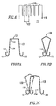
- FIG 6 shows a component 116 for a thermal fuse spring (TFS) in accordance with the present invention.
- Manufacturing of such a TFS starts with cutting a relatively thin, flexible conductive metal sheet material, which suitably conducts surge current, in the form shown in Figure 6.
- the component 116 includes a base 118 and a plurality of fingers 120. In the exemplary embodiment, there is a central distance 122 between adjacent ones of the fingers 120. The distance 122 is preferably selected to match the central distance between a count of six exemplary adjacent MOVs (not shown).
- FIGS 7A-7C show side views of the thermal fuse spring (TFS) component 116 of Figure 6 during sequential manufacturing steps. Bending of TFS is performed in several steps.
- the base 118 is bent to form a first hooked foot 124.
- the finger 120 is bent three times to form a first leg 126, an upper portion 128, a second leg 130 and a second hooked foot 132.
- the upper portion 128 is bent to form a spring member and to make the feet 124,132 touch or nearly touch each other.
- FIGs 8A and 8B show respective un-stretched 136 and stretched 138 thermal fuse springs (TFSs), which are formed in the manner discussed above in connection with Figures 6 and 7A-7C.
- the un-stretched TFS position 136 is the final stage of manufacturing the TFS before the stretched TFS position 138 is soldered to a PCB (not shown).
- the exemplary TFS 138 has six fingers 120 (each of which is bent to form one of the legs 130) for six MOVs (e.g. , MOVs 196,197,198), the present invention is applicable to any count of parallel MOVs (e.g., without limitation, 1, 2, 3-5, 6 or greater).
- the component 116 of Figure 6 is suitably flexible in order that upon disconnection the stretched TFS position 138 rapidly pulls back to the un-stretched TFS position 136 in order to prevent arcing.
- Each of the steps in the assembly of the TFS 136 and soldering of the TFS 138 is preferably selected in view of system (MOV) surge current requirements, TFS fault current requirement, thermal conductivity, spring characteristics, and the electrical characteristics and size of the MOV which is to be protected.
- MOV system
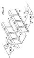
- the process of assembling the TFS 136 of Figure 8A onto a PCB 139 employs a tool, such as the exemplary stretcher device 140, which is employed to mount the stretched TFS 138 of Figure 8B on the PCB 139 and hold the TFS in place during the surface mounting (re-flow) low temperature soldering process.
- the position of the TFS 138 on the PCB 139 is defined by two pins 142,144 on the stretcher device 140.
- the size and shape of holes 146,148 on the PCB 139 suitably match the size and shape of the respective pins 142,144.
- the position of the holes 146,148 defines, with suitable precision, the position of the TFS 138 and its feet on the PCB 139. This is very important, because the position of such feet determines the characteristics of the low temperature solder joint between the bottom surface of those feet and the copper PCB pad 149 beneath those feet.
- the base 118 of the TFS 138 is near the incoming terminal (e.g., phase connector of the SPD) (not shown) for connection to the power source (not shown).
- the finger side of the TFS 138 as shown by the feet 132, is adjacent to the leg of the MOV (not shown).
- the PCB 139 includes various components (not shown) including the TFS 138.
- the pins 142,144 are pushed from the bottom side of the PCB 139 and the stretcher device 140 is removed upward from the PCB for a subsequent use.
- the base foot 124 and the feet 132 ( Figure 8B) of the TFS 138 are suitably held in the proper place on the PCB 139 by the low temperature solder (e.g., 100,102 of Figure 5A).
- the stretcher device 140 includes a base 150 having first and second ends 152,154, first and second sides 156,158, and an elongated opening 160 in the base 150.
- a first alignment member which is the exemplary pin 142, is affixed to the first end 152
- a second alignment member which is the exemplary pin 144, is affixed to the second end 154.
- First and second elongated arcuate members 162,164 are affixed to the first and second sides 156,158, respectively.
- the opening 160 is adapted to receive the spring members 128 of the TFS 136, with the first and second elongated arcuate members 162,164 being adapted to hold the respective hooked foot members 132,124 with the legs 126,130 being stretched thereapart for engagement with the PCB 139.
- the exemplary stretcher device 140 is designed for the TFS 136 having six fingers 120 for six MOVs (not shown), the present invention is applicable to any count of fingers for parallel MOVs ( e.g., without limitation, 1, 2, 3-5, 6 or greater).
- FIGS 11A and 11B show respective un-stretched and stretched thermal fuse springs (TFSs) 166 and 168, which provide protection of MOVs, such as 170,172,174,176, on both sides of the TFS 168 of Figure 11B.
- the TFS 168 includes a middle base portion 178, which has a suitable connection, such as a central opening 180 for a conductive fastener or terminal (not shown), for electrical connection to a phase terminal P.
- the TFS 168 also includes a plurality of first legs 182 and a plurality of second legs 184.
- the first legs 182 are electrically interconnected with corresponding fuse traces 186,188 and surge protection circuits, such as the MOVs 174,176, respectively, which are electrically connected to a common ground G.
- the second legs 184 are electrically interconnected with corresponding fuse traces 190,192 and surge protection circuits, such as the MOVs 170,172, respectively, which are electrically connected to a common neutral N.
- the exemplary double-sided TFS 168 is, thus, suitable for plural phase-to-ground (P-G) and plural phase-to-neutral (P-N) connections and, hence, provides a practical and cost effective assembly.
- first leg 182, the fuse trace 186, and the MOV 174 are electrically interconnected in series between the exemplary phase terminal P and the exemplary ground terminal G.
- second leg 184, the fuse trace 190, and the MOV 170 are electrically interconnected in series between the exemplary phase terminal P and the exemplary neutral terminal N.
- the three terminals P,N,G are also electrically connected to a suitable power source and to a load.
- MOVs 196,197,198 of Figure 8B There are five exemplary different stages or conditions in which the exemplary MOVs, such as MOVs 196,197,198 of Figure 8B, operate: (1) a normal condition in which there are no or insubstantial voltage disturbances; (2) a relatively small overvoltage condition in which the MOV has a steady state temperature; (3) a pre-fault condition in which the MOV has an increasing temperature; (4) a fault condition; and (5) a surge condition.
- the normal condition occurs with a nominal system voltage and with no or insubstantial voltage disturbances.
- the leakage current through the MOV(s) is negligible and is typically in the order of several ⁇ A.
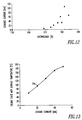
- Figure 12 shows a plot of MOV leakage current versus percent overvoltage.
- the MOV leakage current changes with respect to overvoltage as a non-linear function. As shown, a significant increase in the leakage current occurs when the MOV voltage rises above about 170% of nominal system voltage.
- the leakage current may increase to one or more mA per MOV.
- Such a level of leakage current heats the MOV.
- Figure 13 shows a plot of steady state MOV surface temperature versus MOV leakage current.
- a MOV changes resistance at above a certain temperature (e.g., above 85°C). Hence, if the MOV voltage is constant, then the MOV conducts more and more leakage current as its temperature rises. If these conditions persist, then it leads into "thermal run-away" of the MOV. This process is irreversible and the damage to the MOV is permanent. If a sufficiently abnormal overvoltage is maintained for a sufficiently long period of time, then permanent damage to the MOV structure builds and the MOV enters a pre-fault condition. Otherwise, if the MOV voltage returns to normal, then the MOV might still function, albeit with changed characteristics ( e.g., higher leakage current).
- a higher leakage current in the MOV can be described as a reduced value of maximum continuous overvoltage (MCOV).
- MCOV maximum continuous overvoltage
- a partly damaged MOV starts to conduct a significant amount of current at a lower overvoltage as compared to a new or non-damaged MOV.
- the normal leakage current values shown in Figure 12 at 170% overvoltage might become several times greater.
- Figure 14 shows a plot of abnormal MOV voltage versus time in which plural MOVs, such as the MOV 196 of Figure 8B, is thermally fused by foot 132 of TFS 138 and is overcurrent fused by FTWSH 200.
- a worst case scenario is shown when a double overvoltage (i.e., 200% of nominal system voltage) is applied to the MOVs at time 0.0 s.
- the MOVs are suppressing the overvoltage and the peak voltage is slightly reduced.
- all of the MOVs are conducting (almost) equal currents.
- Figure 15 shows the total current through all of the MOVs. That initial period of time is termed "pre-fault".
- the next stage is termed "fault".
- One among the several MOVs is the weakest. Small initial differences between the MOVs become bigger and bigger during the pre-fault conditions.
- the resistance of the weakest MOV is the smallest and that particular MOV conducts more then the other MOVs. Because that MOV gets hotter, the resistance drops further and increasing levels of current flow through the MOV. In turn, the weakest MOV becomes shorted and almost the entire current flows through only the single MOV.
- an abnormal overvoltage of about 200% nominal voltage is applied to the phase P and ground G connections to the MOVs 196,197,198 which are connected in parallel.
- these MOVs are clamping at about 190% nominal voltage (e.g., about 300 Vpeak).
- This is a pre-fault condition, which increases the temperature of the MOVs.
- the weakest MOV e.g., MOV 197) among the three exemplary MOVs is shorted and the clamping voltage drops down to about 200 Vpeak. This is the fault condition, which remains for four cycles 204.
- the failing MOV 197 is disconnected ( e.g., by the FTWSH 206 and/or the TFS leg 208) and the remaining MOVs (e.g., MOVs 196,198) are clamping at about 190% nominal voltage for 16 cycles 210 until the next weakest MOV (e.g., MOV 198) fails.
- the second failure condition lasts for two cycles 212, when the second MOV (e.g., MOV 198) is disconnected ( e.g., by the FTWSH 214 and/or the TFS leg 216).
- the next (and final in this example) pre-fault condition is for three cycles 218, which is followed by a fault condition for the next four cycles 220.
- the third MOV (e.g., MOV 196) is disconnected ( e.g., by the FTWSH 200 and/or the TFS leg 222).
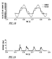
- Figure 15 shows a plot of MOV current versus time for the corresponding overvoltage conditions of Figure 14.
- the amount of current flowing through a shorted MOV depends mostly upon the power source's impedance.
- the maximum fault current shown in Figure 15 is about several hundred amperes.
- the duration of the "fault” depends upon several conditions, with the maximum fault current being the most important. Higher fault current forces the SPD circuitry to degrade at a faster rate.
- the duration of the first fault current on Figure 15 is about four cycles.
- the corresponding four cycles of Figure 14 show a voltage drop during which "fault" the MOV is shorted. Then, after those four cycles, the shorted MOV is disconnected.
- the plot includes nine cycles 226 of pre-fault current, four cycles 228 of fault current, 16 cycles 230 of pre-fault current, two cycles 232 of fault current, three cycles 234 of pre-fault current, and four cycles 236 of fault current.
- the pre-fault current is biggest at the beginning cycles 226, when all three exemplary MOVs 196,197,198 are clamping.
- the subsequent pre-fault current cycles at 230 (two MOVs) and 234 (one MOV) have progressively smaller pre-fault currents, because only two MOVs and one MOV, respectively, are in the circuit.
- the pre-fault current is shared among any remaining non-disconnected MOVs, any fault current is (generally) through only one (shorted) MOV.
- MOV failure might be shorter or substantially longer in duration. Such failure depends upon the MOV overvoltage /MCOV ratio, and the count of the parallel MOVs.
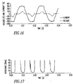
- Figure 16 shows a plot of pre-fault abnormal MOV voltage and corresponding current versus time in which parallel MOVs, such as the MOV 196 of Figure 8B, is thermally fused by foot 132 of TFS 138 and is overcurrent fused by FTWSH 200.
- These voltage and current plots are from some of the first nine pre-fault cycles 202 (about 0.0 to about 0.04 s) of Figure 14 and corresponding cycles 226 of Figure 15.
- the voltage is shown by a deformed sine wave.
- the peak of the voltage is about 304 V, instead of the peak abnormal voltage of about 338 V ( i.e., 120 V x 200% x 1.41).
- the peak current is millions times higher than the current at normal conditions.
- Figure 17 shows a corresponding plot of MOV resistance versus time for the overvoltage conditions of Figure 16.
- the plotted resistance is the parallel resistance of several MOVs (e.g., MOVs 196,197,198).
- MOVs 196,197,198 MOVs 196,197,198
- the plotted resistance is multiplied by the count of parallel MOVs.
- the "pre-fault" resistance of Figure 17 is significant as compared to a conventional power source impedance. Hence, the "pre-fault" current is limited by MOVs' parallel resistance.
- Figure 18 shows a plot of a fault condition for abnormal MOV voltage and corresponding current versus time in which a MOV, such as the MOV 196 of Figure 8B, is thermally fused by foot 132 of TFS 138 and is overcurrent fused by FTWSH 200.
- the time duration shown in Figure 18 corresponds to about the 0.14 s to 0.20 s time of Figures 14 and 15.
- the peak of the voltage waveform is about 200 V, rather than the peak of the abnormal voltage, namely about 338 V.
- the peak current through one MOV is about 400 A. Furthermore, this value might be several times higher if permitted by the power source impedance, in which a lower source impedance sources a higher fault current.
- the MOV must be disconnected before it conducts enough energy to cause a catastrophic failure.
- the voltage magnitude is lower and the current magnitude is much larger than the corresponding voltage and current magnitudes during the pre-fault cycles 202 and 226 of Figures 14 and 15, respectively. Since this current flows through only a single (shorted) MOV, the amount of heat generated by the MOV is substantial.
- Figure 19 is derived from the fault voltage and fault current of Figure 18 and shows the resistance of the single (shorted) MOV versus time.
- An MOV is a non-linear component and the MOV resistance changes between near infinite and about 30 ⁇ . This resistance limits the current through one MOV to below about 5 A rms . This current heats the MOV and the temperature rises on all parallel-connected MOVs until the weakest MOV becomes shorted. At that point, the MOV enters a fault condition and the shorted MOV conducts (almost) all of the available current ( Figure 18).
- the shorted MOV resistance is still non-linear and changes in the range from about 0.4 to about 10 ⁇ . This resistance is voltage-dependent as shown by its magnitude being comparable with a common source impedance ( e.g., 0.7 ⁇ ). If the source impedance is smaller, then the fault current is larger and the time to disconnect a failing MOV must be shorter.
- a common source impedance e.g.
- a SPD in accordance with the present invention preferably includes the following for improved catastrophic failure protection: (1) each MOV has a dedicated thermal fuse spring (TFS) combined with a dedicated fuse trace (FTWSH); (2) the TFS and the FTWSH withstand surge current conditions and have a surge current rating which is suitable for letting a surge go through the protected MOV; (3) the TFS, FTWSH and MOV combination is electrically connected in series; (4) during normal conditions, the leakage current through the series connection of the TFS, FTWSH and MOV is in the range of about several ⁇ A; (5) if the leakage current through the MOV rises up to about several mA, then that condition is an abnormal condition leading into failure ( e.g., a pre-fault condition); (6) heat for the thermal disconnection device or TFS is provided by the overheated MOV; and (7) the FTWSH employs a through hole filled with solder (e.g., without limitation, conventional solder) in order to shorten the disconnection time during a
- the invention is applicable to surge protection devices in which the MOV (e.g., 74 or 74A) is electrically connected at the other side of the TFS and FTWSH or in series between the TFS 76 and the PCB copper trace ( e.g., 88 or 88A).
- the invention is further applicable to such surge protection devices in which the FTWSH is electrically connected to one input terminal (e.g., phase input, ground or neutral input) and the TFS is electrically connected to another input terminal ( e.g., ground or neutral input, phase input) of those devices.
Landscapes
- Engineering & Computer Science (AREA)
- Microelectronics & Electronic Packaging (AREA)
- Physics & Mathematics (AREA)
- Electromagnetism (AREA)
- Fuses (AREA)
Abstract
Description
- 2
- surge protection device (SPD) circuit
- 4
- conventional overcurrent fuse
- 6
- metal oxide varistor (MOV)
- 8
- MOV
- 10
- MOV
- 12
- thermal cut-off (TCO) device
- 14
- thermal cut-off (TCO) device
- 16
- conventional AC power circuit
- 18
- power input
- 20
- phase connection
- 22
- neutral connection
- 24
- ground connection
- 26
- power output
- 28
- phase connection
- 30
- neutral connection
- 32
- ground connection
- 34
- circuit breaker or switch
- 36
- SPD
- 38
- plurality of MOVs
- 39
- nominal leakage current
- 40
- fuses
- 41
- nominal system voltage
- 42
- first pre-fault condition
- 44
- first fault condition
- 46
- second pre-fault condition
- 48
- second fault condition
- 50
- third pre-fault condition
- 52
- third fault condition
- 54
- log-log plot
- 56
- log-log plot
- 58
- conduction region
- 60
- disconnection region
- 62
- point
- 65
- point
- 68
- point
- 70
- SPD
- 72
- printed circuit board (PCB)
- 74
- MOV
- 76
- thermal fuse spring (TFS)
- 78
- fuse trace with solder hole (FTWSH)
- 80
- MOV lead
- 82
- MOV lead
- 84
- PCB through hole
- 86
- PCB through hole
- 88
- PCB copper traces
- 90
- PCB copper trace
- 92
- PCB through hole
- 94
- conventional solder
- 96
- conventional solder
- 98
- copper trace
- 100
- low temperature solder
- 102
- low temperature solder
- 104
- foot
- 106
- foot
- 108
- PCB copper trace
- 110
- heat
- 112
- leg
- 114
- opposing leg
- 115
- direction
- 116
- component
- 118
- base
- 120
- fingers
- 122
- central distance
- 124
- first foot
- 126
- first leg
- 128
- upper portion
- 130
- second leg
- 132
- second foot
- 134
- direction of stretching
- 136
- un-stretched TFS position
- 138
- stretched TFS position
- 139
- PCB
- 140
- stretcher device
- 142
- pin
- 144
- pin
- 146
- hole
- 148
- hole
- 149
- copper PCB pad
- 150
- base
- 152
- first end
- 154
- second end
- 156
- first side
- 158
- second side
- 160
- opening
- 162
- first elongated arcuate member
- 164
- second elongated arcuate member
- 166
- un-stretched thermal fuse spring (TFS)
- 168
- stretched thermal fuse spring (TFS)
- 170
- MOV
- 172
- MOV
- 174
- MOV
- 176
- MOV
- 178
- conductive middle base portion
- 180
- central opening
- 182
- conductive first legs
- 184
- conductive second legs
- 186
- fuse trace
- 188
- fuse trace
- 190
- fuse trace
- 192
- fuse trace
- 194
- point
- 196
- MOV
- 197
- MOV
- 198
- MOV
- 200
- FTWSH
- 202
- first nine cycles
- 204
- four cycles
- 206
- FTWSH
- 208
- TFS leg
- 210
- 16 cycles
- 212
- two cycles
- 214
- FTWSH
- 216
- TFS leg
- 218
- three cycles
- 220
- four cycles
- 222
- TFS leg
- 224
- remaining cycles
- 226
- nine cycles of pre-fault current
- 228
- four cycles of fault current
- 230
- 16 cycles of pre-fault current
- 232
- two cycles of fault current
- 234
- three cycles of pre-fault current
- 236
- four cycles of fault current
Claims (44)
- A surge protection device (70) for a load supplied with at least one voltage (41) from a power source, said surge protection device comprising:at least two terminals (P, G, N) adapted to receive said voltage; anda plurality of surge protection circuits, each of said surge protection circuits comprising:a thermal fuse spring (76),at least one means (74) for clamping a voltage, andat least one fuse trace (78), each one of said at least one fuse trace corresponding to one of said at least one means for clamping a voltage,with said thermal fuse spring, one of said at least one fuse trace and a corresponding one of said at least one means for clamping a voltage being electrically interconnected in series between said terminals, in order to form at least one series electrical connection between said terminals,with said thermal fuse spring being adapted to disconnect said at least one series electrical connection between said terminals under first fault conditions of said at least one means for clamping a voltage, said first fault conditions including a first current (62) through one of said at least one means for clamping a voltage for a first duration,with said thermal fuse spring and said at least one fuse trace being adapted to cooperatively disconnect a corresponding one of said at least one series electrical connection between said terminals under second fault conditions of said at least one means for clamping a voltage, said second fault conditions including a second current (65) through one of said at least one means for clamping a voltage for a second duration,with said second current being greater than said first current, andwith said first duration being greater than said second duration.
- The surge protection device of Claim 1 wherein said thermal fuse spring includes a first spring member (114), which is electrically connected to one of said terminals, and a second spring member (112); wherein said at least one fuse trace is a fuse trace having an input, which is electrically connected to said second spring member, and an output; and wherein said means for clamping a voltage has a first lead (80), which is electrically connected to the output of said fuse trace, and a second lead (82), which is electrically connected to another one of said terminals.
- The surge protection device of Claim 2 wherein said at least one means for clamping a voltage includes a metal oxide varistor (74).
- The surge protection device of Claim 1 wherein said thermal fuse spring includes a first spring member (114), which is electrically connected to one of said terminals, and a second spring member (112); wherein said at least one fuse trace is a pair of fuse traces (78A,78B), with each one of said fuse traces having an input, which is electrically connected to said second spring member, and an output; and wherein said means for clamping a voltage is a pair of metal oxide varistors (74A,74B), with each one of said metal oxide varistors having a first lead (80A,80B), which is electrically connected to the output of the corresponding one of said fuse traces, and a second lead (82A), which is electrically connected to another one of said terminals.
- The surge protection device of Claim 1 wherein said thermal fuse spring includes a first spring member (114), which is electrically connected to one of said terminals, and a second spring member (112); wherein said means for clamping a voltage is a metal oxide varistor (74) having a first lead, which is electrically connected to the second spring member, and a second lead; and wherein said at least one fuse trace (78) is a fuse trace having an input, which is electrically connected to said second lead, and an output, which is electrically connected to another one of said terminals.
- The surge protection device of Claim 1 wherein said at least one fuse trace is a fuse trace (78) having an input, which is electrically connected to one of said terminals, and an output; wherein said means for clamping a voltage is a metal oxide varistor (74) having a first lead, which is electrically connected to the output of said fuse trace, and a second lead; and wherein said thermal fuse spring includes a first spring member, which is electrically connected to said second lead, and a second spring member, which is electrically connected to another one of said terminals.
- The surge protection device of Claim 1 wherein each of said thermal fuse spring, said at least one fuse trace, and said at least one means for clamping a voltage has a surge current rating, with each of said surge current ratings being about the same.
- The surge protection device of Claim 1 wherein said at least one fuse trace is a fuse trace (78); wherein said at least one series electrical connection is a series electrical connection; wherein said at least one means for clamping a voltage is a metal oxide varistor (74), which has a leakage current )39) flowing therethrough; and wherein said leakage current flows through said series electrical connection between said terminals under normal operating conditions.
- The surge protection device of Claim 1 wherein said first fault conditions correspond to a first failure of one of said at least one means for clamping a voltage; wherein said second fault conditions correspond to a second failure of said one of said at least one means for clamping a voltage; and wherein said first failure corresponds to a first impedance of said power source, and said second failure corresponds to a second impedance of said power source, said second impedance being less than said first impedance.
- The surge protection device of Claim 9 wherein said surge protection circuits include a printed circuit board (72); wherein said at least one fuse trace is a fuse trace (78) on said printed circuit board; wherein said thermal fuse spring includes a first spring member (114), which is electrically connected to one of said terminals, and a second spring member (112), which is soldered to said fuse trace and biased toward said first spring member; and wherein said fuse trace melts and arcs in response to said second failure, in order to heat said second spring member and release said second spring member from said fuse trace.
- The surge protection device of Claim 10 wherein the first and second spring members of said thermal fuse spring are each soldered to said printed circuit board with a solder (100,102) having a melting temperature of about 80 degrees C to about 120 degrees C.
- The surge protection device of Claim 1 wherein said at least one means for clamping a voltage is selected from a group comprising: a metal oxide varistor, a zener diode, and a silicon avalanche diode.
- The surge protection device of Claim 1 wherein said thermal fuse spring includes a first spring member (114), which is electrically connected to one of said terminals, and a second spring member (112); wherein said at least one fuse trace includes a first fuse trace (78A) having a first input electrically interconnected with the second member of said thermal fuse spring and having a first output, and a second fuse trace (78B) having a second input electrically interconnected with the second member of said thermal fuse spring and having a second output; and wherein said at least one means for clamping a voltage comprises a first metal oxide varistor (74A) electrically connected to the first output and a second metal oxide varistor (74B) electrically connected to the second output.
- The surge protection device of Claim 1 wherein said terminals include a phase input (P) and a ground input (G); and wherein said surge protection circuits are electrically interconnected between said phase and ground inputs.
- The surge protection device of Claim 1 wherein said at least one means for clamping a voltage is a metal oxide varistor (74) having a catastrophic failure state under overvoltage conditions; wherein said at least one fuse trace is a fuse trace (78); wherein each of said thermal fuse spring and said fuse trace has a time versus current characteristic which is coordinated with the catastrophic failure state of said metal oxide varistor in order to disconnect said metal oxide varistor from said voltage under said overvoltage conditions; and wherein at least one of said thermal fuse spring and said fuse trace disconnects said metal oxide varistor from said voltage in order to prevent said catastrophic failure state under said overvoltage conditions.
- The surge protection device of Claim 15 wherein the time versus current characteristic of said thermal fuse spring is adapted for disconnection of said metal oxide varistor from said voltage under a first fault current (62) flowing through said metal oxide varistor; and wherein the time versus current characteristic of said fuse trace is adapted for disconnection of said metal oxide varistor from said voltage under a second fault current (68) flowing through said metal oxide varistor, with said second fault current being greater than said first fault current.
- The surge protection device of Claim 1 wherein said thermal fuse spring comprises a base (118) and a plurality of legs (126,130), with said base being electrically interconnected with one of said terminals and said legs; wherein said at least one fuse trace includes a plurality of fuse traces (78A,78B); wherein said at least one means for clamping a voltage includes a plurality of means (74A,74B) for clamping a voltage; and wherein each of said legs is electrically interconnected with a corresponding pair of one of said fuse traces and one of said plurality of means for clamping a voltage.
- The surge protection device of Claim 2 wherein said surge protection circuits include a printed circuit board (72); and wherein said fuse trace includes a first conductive trace (88) on said printed circuit board, a conductive through hole (92) in said printed circuit board, and a second conductive trace on said printed circuit board, with said first conductive trace (90) being electrically connected to the input of said fuse trace and to said conductive through hole, and with said second conductive trace being electrically connected to said conductive through hole and to the output of said fuse trace.
- The surge protection device of Claim 18 wherein the conductive through hole of said fuse trace is filled with solder (96), in order to shorten a disconnection time of said fuse trace during an overcurrent condition.
- The surge protection device of Claim 19 wherein said solder has a melting temperature of between about 175 degrees C and about 250 degrees C.
- The surge protection device of Claim 20 wherein said at least one means for clamping a voltage has a fault current rating; and wherein the fault current rating of said fuse trace is less than the fault current rating of said at least one means for clamping a voltage.
- The surge protection device of Claim 1 wherein said terminals include a phase input (P), a neutral input (N), and a ground input (G); and wherein said at least one means for clamping a voltage includes a plurality of first metal oxide varistors (170,172) between said phase input and said neutral input, and a plurality of second metal oxide varistors (174,176) between said phase input and said ground input.
- The surge protection device of Claim 22 wherein each of said surge protection circuits is a plurality of first surge protection circuits and a plurality of second surge protection circuits, with each of said first surge protection circuits being electrically connected in parallel, and with each of said second surge protection circuits being electrically connected in parallel; wherein said thermal fuse springs comprise a base (178), a plurality of first legs (182) and a plurality of second legs (184), with said base being electrically interconnected with said phase input, with each of said first legs being electrically interconnected with a corresponding pair of said fuse traces (186,188), and with each of said second legs being electrically interconnected with a corresponding pair of said fuse traces (190,192).
- The surge protection device of Claim 2 wherein said surge protection circuits include a printed circuit board (72) having a first conductor (108) which is electrically connected to one of said terminals, and a second conductor (88) which is electrically interconnected with the input of said fuse trace; wherein the first spring member (114) of said thermal fuse spring is soldered to the first conductor of said printed circuit board and the second spring member (112) of said thermal fuse spring is stretched away from said first spring member and soldered to the second conductor of said printed circuit board.
- The surge protection device of Claim 24 wherein the first and second spring members (114,112) of said thermal fuse spring are each soldered to said printed circuit board with a solder (102,100) having a melting temperature of about 80 degrees C to about 120 degrees C.
- The surge protection device of Claim 25 wherein said printed circuit board includes a conductive through hole (92) which is part of said fuse trace (78); and wherein said conductive through hole is filled with solder (86) having a melting temperature of between about 175 degrees C and about 250 degrees C, in order to shorten a disconnection time of said fuse trace during an overcurrent condition.
- The surge protection device of Claim 26 wherein each of said thermal fuse spring and said fuse trace has a time versus current characteristic (54,56) which is coordinated with said at least one means for clamping a voltage in order to disconnect said at least one means for clamping a voltage from said voltage of said power source under overvoltage conditions; wherein the time versus current characteristic (54) of said thermal fuse spring is adapted for disconnection of said means for clamping a voltage from said voltage under a first fault current (62) flowing through said means for clamping a voltage; and wherein the time versus current characteristic (56) of said fuse trace is adapted for disconnection of said means for clamping a voltage from said voltage under a second fault current (68) flowing through said means for clamping a voltage, with said second fault current being greater than said first fault current.
- A method of manufacturing a thermal fuse spring (136) comprising the steps of:cutting a flexible conductive material (116) to form a base (118) and a plurality of fingers (120);bending said base and said fingers to form a plurality of thermal fuse spring elements (120) having a common base (118) and a plurality of independent leg elements (130);stretching each of said leg elements away from said common base;positioning said common base and said stretched leg elements on a printed circuit board (139); andsoldering said common base and said stretched leg elements to said printed circuit board.
- The method of Claim 28 further comprising:employing low temperature solder (100,102) to solder said common base and said stretched leg elements to said printed circuit board.
- The method of Claim 29 further comprising:employing said low temperature solder having a melting temperature of about 80 degrees C to about 120 degrees C.
- The method of Claim 30 further comprising:employing a stretching device (140) for each of said stretching, positioning and soldering steps.
- The method of Claim 31 further comprising:engaging said printed circuit board with said stretching device during said positioning step.
- The method of Claim 32 further comprising:disengaging said stretching device from said printed circuit board after said soldering step.
- The method of Claim 31 further comprising:stretching said thermal fuse spring elements with said stretching device; andplacing said thermal fuse spring elements and said stretching device on said printed circuit board.
- The method of Claim 34 further comprising:employing a pair of mounting holes (146,148) on said printed circuit board;employing a pair of pins (142,144) on said stretching device aligned with said mounting holes; andmounting said pins in said mounting holes.
- The method of Claim 35 further comprising:employing conductors (149) on said printed circuit board; andemploying said pins and said mounting holes to align the common base and the stretched leg elements of said thermal fuse spring elements with said conductors on said printed circuit board.
- The method of Claim 34 further comprising:correlating surge current requirements and fault current requirements of said thermal fuse spring elements with surge current requirements and fault current requirements of a metal oxide varistor.
- A stretcher device (140) for use in mounting at least one thermal fuse (76,118) spring on a printed circuit board (139), said thermal fuse spring including a spring member (128) having a pair of legs (112,114) each of which has a hooked foot member (124,132), said stretcher device comprising:a base (150) including first and second ends (152,154), first and second sides (156,150), and an elongated opening (16) in said base;a first alignment member (142) affixed to the first end of said base;a second alignment member (144) affixed to the second end of said base;a first elongated arcuate member (162) affixed to the first side (156) of said base; anda second elongated arcuate member (164) affixed to the second side (158) of said base, with the opening of said base adapted to receive the spring member (128) of said thermal fuse spring, and with said first and second elongated arcuate members adapted to hold the hooked foot members of said thermal fuse spring with the legs thereof being stretched thereapart for engagement with said printed circuit board.
- The stretcher device of Claim 38 wherein said at least one thermal fuse spring is a plurality of thermal fuse springs; and wherein each of said first and second elongated arcuate members is adapted to hold a plurality of the hooked foot members of said thermal fuse springs.
- A surge protection device (70) for a load supplied with a voltage from a power source, said surge protection device comprising:a plurality of terminals (P,G) adapted to receive said voltage;a printed circuit board (72); anda plurality of surge protection circuits, each of said surge protection circuits comprising:a thermal fuse spring (76) on said printed circuit board, means (74) for clamping a voltage,a fuse trace (78) electrically interconnected in series with said thermal fuse spring and said means for clamping a voltage between said terminals, in order to form a series electrical connection between said terminals, said fuse trace including at least one conductive trace (88,90) on said printed circuit board and also including a conductive through hole (92) in said printed circuit board and electrically connected to said at least one conductive trace, andwith said thermal fuse spring being adapted to disconnect said series electrical connection between said terminals under first fault conditions of said means for clamping a voltage, andwith said thermal fuse spring and said fuse trace being adapted to cooperatively disconnect said series electrical connection between said terminals under second fault conditions of said means for clamping a voltage.
- The surge protection device of Claim 40 wherein said conductive through hole is filled with solder (96) having a melting temperature of between about 175 degrees C and about 250 degrees C, in order to shorten a disconnection time of said at least one conductive trace during an overcurrent condition.
- The surge protection device of Claim 41 wherein said thermal fuse spring includes a first spring member (114) electrically interconnected with one of said terminals and a second spring member (112) electrically interconnected with said fuse trace, with at least one of said first and second spring members being soldered to said printed circuit board with a solder (102,100) having a melting temperature of about 80 degrees C to about 120 degrees C.
- The surge protection device of Claim 40 wherein the conductive through hole of said fuse trace is filled with solder (96), in order to shorten a disconnection time of said at least one conductive trace during an overcurrent condition.
- The surge protection device of Claim 40 wherein said thermal fuse spring and said fuse trace cooperatively provide coordinated disconnection of said means for clamping a voltage from said voltage of said power source under predetermined overvoltage conditions of said means for clamping a voltage.
Applications Claiming Priority (2)
| Application Number | Priority Date | Filing Date | Title |
|---|---|---|---|
| US836888 | 2001-04-16 | ||
| US09/836,888 US6636409B2 (en) | 2001-04-16 | 2001-04-16 | Surge protection device including a thermal fuse spring, a fuse trace and a voltage clamping device |
Publications (2)
| Publication Number | Publication Date |
|---|---|
| EP1251528A2 true EP1251528A2 (en) | 2002-10-23 |
| EP1251528A3 EP1251528A3 (en) | 2004-09-22 |
Family
ID=25272980
Family Applications (1)
| Application Number | Title | Priority Date | Filing Date |
|---|---|---|---|
| EP02008565A Withdrawn EP1251528A3 (en) | 2001-04-16 | 2002-04-16 | Surge protection device |
Country Status (5)
| Country | Link |
|---|---|
| US (1) | US6636409B2 (en) |
| EP (1) | EP1251528A3 (en) |
| CN (1) | CN1381935A (en) |
| CA (1) | CA2381749A1 (en) |
| MX (1) | MXPA02003825A (en) |
Cited By (2)
| Publication number | Priority date | Publication date | Assignee | Title |
|---|---|---|---|---|
| DE102005034535A1 (en) * | 2005-07-23 | 2007-01-25 | Conti Temic Microelectronic Gmbh | Circuit plate for an electronic automobile controller has fuse plugs inserted into the tracks that melt to prevent overload |
| EP1826780A4 (en) * | 2004-12-13 | 2010-08-11 | Zhonghou Xu | VARISTANCE AND THERMAL FUSE OF ALLOY TYPE |
Families Citing this family (37)
| Publication number | Priority date | Publication date | Assignee | Title |
|---|---|---|---|---|
| JP3895911B2 (en) * | 2000-08-28 | 2007-03-22 | 隆 河東田 | Main component of surge protection device and manufacturing method thereof |
| US6816352B2 (en) * | 2001-02-16 | 2004-11-09 | Panamax | Abnormal voltage protection circuit |
| US20040066597A1 (en) * | 2002-10-02 | 2004-04-08 | Losey Francis R. | Telemetry shield diffuser |
| US7417841B2 (en) * | 2003-12-04 | 2008-08-26 | Surge Suppression, Inc. | Apparatus and method for fusing voltage surge and transient anomalies in a surge suppression device |
| US7460346B2 (en) * | 2005-03-24 | 2008-12-02 | Honeywell International Inc. | Arc fault detection and confirmation using voltage and current analysis |
| CN100352122C (en) * | 2005-07-13 | 2007-11-28 | 浙江神龙电器有限公司 | Surge protector with piece separation |
| WO2007064960A2 (en) * | 2005-11-30 | 2007-06-07 | University Of South Florida | Mov failure mode identification |
| AU2006252237C1 (en) * | 2006-01-06 | 2009-11-12 | Belkin International, Inc. | Surge suppressor, electronic device, and method with components oriented for improved safety |
| US20070159756A1 (en) * | 2006-01-06 | 2007-07-12 | Belkin Corporation | Surge suppressor, electronic device, and method with components oriented for improved safety |
| US20070159758A1 (en) * | 2006-01-09 | 2007-07-12 | Ceramate Technical Co., Ltd. | Protective circuit for thunderbolt abrupt waves |
| US7511933B2 (en) * | 2006-02-17 | 2009-03-31 | Eaton Corporation | System and method for protecting transient-suppressing elements against over-voltage conditions |
| US20070201177A1 (en) * | 2006-02-27 | 2007-08-30 | Eaton Corporation | Surge protection device disconnector |
| US7348872B1 (en) | 2006-11-10 | 2008-03-25 | Eaton Corporation | Fuse having a plurality of configurable thermal ceilings |
| JP5130233B2 (en) | 2009-01-21 | 2013-01-30 | デクセリアルズ株式会社 | Protective element |
| JP5301298B2 (en) * | 2009-01-21 | 2013-09-25 | デクセリアルズ株式会社 | Protective element |
| JP5130232B2 (en) | 2009-01-21 | 2013-01-30 | デクセリアルズ株式会社 | Protective element |
| TWI413997B (en) * | 2009-11-06 | 2013-11-01 | Powertech Ind Ltd | Switch module |
| CN102315629A (en) * | 2010-07-01 | 2012-01-11 | 鸿富锦精密工业(深圳)有限公司 | Protection circuit and electronic device with same |
| US11251608B2 (en) | 2010-07-13 | 2022-02-15 | Raycap S.A. | Overvoltage protection system for wireless communication systems |
| US10062530B2 (en) * | 2012-10-26 | 2018-08-28 | Dongguan Littelfuse Electronics Co., Ltd. | Surge protection device |
| DE102013021936B3 (en) * | 2013-10-08 | 2015-02-12 | Dehn + Söhne Gmbh + Co. Kg | Compact, prefabricatable surge protection device |
| US9337642B2 (en) | 2013-12-06 | 2016-05-10 | Eaton Corporation | Surge protection apparatus having multiple surge protection devices and display |
| DE102014111772B4 (en) * | 2014-08-18 | 2016-03-24 | Borgwarner Ludwigsburg Gmbh | Fuse for an electrical circuit and circuit board with a fuse |
| US20160233041A1 (en) * | 2015-02-09 | 2016-08-11 | Yi-Hsiang Wang | Switch module of built-in anti-surge disconnection structure |
| US10148079B2 (en) | 2015-04-07 | 2018-12-04 | Dongguan Littelfuse Electronics Co., Ltd. | Surge protection device |
| US20170047180A1 (en) * | 2015-08-12 | 2017-02-16 | Yi-Hsiang Wang | Switch module of built-in anti-surge disconnection structure |
| CN107633983A (en) * | 2017-10-27 | 2018-01-26 | 苏州市职业大学 | A kind of pre-tensioner fuse of PCB surface mounted type |
| US10971928B2 (en) * | 2018-08-28 | 2021-04-06 | Raycap Ip Assets Ltd | Integrated overvoltage protection and monitoring system |
| CN110601164B (en) * | 2019-08-23 | 2024-03-22 | 隆科电子(惠阳)有限公司 | Rotary linkage thermal disengaging device capable of blocking in sequence |
| US11677164B2 (en) | 2019-09-25 | 2023-06-13 | Raycap Ip Assets Ltd | Hybrid antenna distribution unit |
| CN111097983B (en) * | 2019-12-23 | 2021-10-01 | 中国航天空气动力技术研究院 | A kind of temperature control switch and preparation method thereof |
| US12237134B2 (en) | 2021-12-28 | 2025-02-25 | Raycap Ip Assets Ltd | Circuit protection for hybrid antenna distribution units |
| CN115275958B (en) * | 2022-09-28 | 2023-03-17 | 深圳市高斯宝电气技术有限公司 | Lightning protection circuit of power down circuit of communication power supply |
| WO2024100487A1 (en) * | 2022-11-11 | 2024-05-16 | Prolec, S. A. De C. V. | Surge protective device and method, and an electric system with said protective device |
| CN117543524A (en) * | 2023-11-21 | 2024-02-09 | 上海舜华新能源系统有限公司 | Circuit board anti-surge protection circuit used in outdoor environment |
| CN118300050B (en) * | 2024-04-12 | 2024-10-18 | 南京林业大学 | A surge protection system and PCB circuit structure for RS485 level conversion circuit |
| CN121237618A (en) * | 2024-06-28 | 2025-12-30 | 清华大学 | A condition monitoring scheme for MOV series fuses |
Family Cites Families (13)
| Publication number | Priority date | Publication date | Assignee | Title |
|---|---|---|---|---|
| DE3743857A1 (en) | 1987-07-30 | 1989-02-09 | Wickmann Werke Gmbh | ELECTRICAL FUSE AND METHOD FOR THEIR PRODUCTION |
| US5115220A (en) | 1991-01-03 | 1992-05-19 | Gould, Inc. | Fuse with thin film fusible element supported on a substrate |
| DE4209542C2 (en) | 1992-03-24 | 1995-07-06 | Roederstein Kondensatoren | Fusible link with spring arm |
| DE4219304C2 (en) | 1992-06-12 | 1994-03-31 | Roederstein Kondensatoren | Reliable overcurrent protection component with a small footprint and simple construction |
| DE4219554A1 (en) | 1992-06-15 | 1993-12-16 | Siemens Ag | Thermal fuse and procedure for its activation |
| US5412526A (en) * | 1993-02-10 | 1995-05-02 | Square D Company | Surge arrester circuit and housing therefor |
| JPH0775249A (en) * | 1993-08-31 | 1995-03-17 | Anden Kk | Surge absorption circuit |
| DE4437122C2 (en) * | 1994-10-01 | 1996-07-18 | Krone Ag | Surge protection plug |
| DE19721047A1 (en) * | 1997-05-09 | 1998-11-12 | Krone Ag | Surge protection module |
| DE19752781A1 (en) | 1997-11-28 | 1999-06-02 | Wabco Gmbh | Circuit arrangement for protecting an electrical component from an electrical potential |
| US5896080A (en) | 1998-04-10 | 1999-04-20 | Kun-Ming Tsai | Thermal fuse for fixing on a circuit board |
| CA2339069C (en) * | 1998-07-24 | 2007-11-20 | American Power Conversion Corporation | Universal surge protector for notebook computers |
| US6226162B1 (en) * | 1999-06-02 | 2001-05-01 | Eaton Corporation | Surge suppression network responsive to the rate of change of power disturbances |
-
2001
- 2001-04-16 US US09/836,888 patent/US6636409B2/en not_active Expired - Lifetime
-
2002
- 2002-04-15 CA CA002381749A patent/CA2381749A1/en not_active Abandoned
- 2002-04-16 CN CN02116864.4A patent/CN1381935A/en active Pending
- 2002-04-16 EP EP02008565A patent/EP1251528A3/en not_active Withdrawn
- 2002-04-16 MX MXPA02003825A patent/MXPA02003825A/en unknown
Cited By (2)
| Publication number | Priority date | Publication date | Assignee | Title |
|---|---|---|---|---|
| EP1826780A4 (en) * | 2004-12-13 | 2010-08-11 | Zhonghou Xu | VARISTANCE AND THERMAL FUSE OF ALLOY TYPE |
| DE102005034535A1 (en) * | 2005-07-23 | 2007-01-25 | Conti Temic Microelectronic Gmbh | Circuit plate for an electronic automobile controller has fuse plugs inserted into the tracks that melt to prevent overload |
Also Published As
| Publication number | Publication date |
|---|---|
| US6636409B2 (en) | 2003-10-21 |
| CA2381749A1 (en) | 2002-10-16 |
| MXPA02003825A (en) | 2002-11-08 |
| CN1381935A (en) | 2002-11-27 |
| US20020149899A1 (en) | 2002-10-17 |
| EP1251528A3 (en) | 2004-09-22 |
Similar Documents
| Publication | Publication Date | Title |
|---|---|---|
| US6636409B2 (en) | Surge protection device including a thermal fuse spring, a fuse trace and a voltage clamping device | |
| US11223200B2 (en) | Surge protective devices, circuits, modules and systems including same | |
| EP2008292B1 (en) | Transient voltage surge suppression | |
| CA2115340C (en) | Surge arrester circuit and housing therefor | |
| CN115986679A (en) | Surge protection device module including an integral thermal isolation switching mechanism and method | |
| CN201057626Y (en) | Superheating protection circuit for semiconductor element | |
| TW201230116A (en) | Compact transient voltage surge suppression device | |
| CN111837308B (en) | Novel lightning protection overvoltage crowbar and protection device | |
| EP1991994A1 (en) | Surge protection device disconnector | |
| CN107919658A (en) | It is combined with the Thermal protection rheostat of series connection and the component of discharge tube | |
| US5247273A (en) | Surge absorber for protection of communication equipment connected to communication lines | |
| CN117175521A (en) | Surge protective devices, circuits, modules and systems including the same | |
| CN1132195C (en) | Hybrid circuit device with overload protection | |
| EP0395231B1 (en) | Protective arrangement for telecommunications line interface circuit | |
| CN109727739B (en) | Overvoltage protection device comprising a plurality of varistor wafers | |
| AU2019100388A4 (en) | Protection circuit | |
| US20250095890A1 (en) | Surge protection devices including varistors | |
| CN121172684A (en) | Overload protector and power equipment | |
| EP2378527A2 (en) | Device for overvoltage protection | |
| CN121532848A (en) | Circuit with resistive fuse | |
| JP2025006760A (en) | Surge protection device isolation device | |
| JPH01176686A (en) | Surge absorber | |
| WO2001018934A1 (en) | Method and apparatus for protecting electronic equipment coupled to a telephone line | |
| Wilkins et al. | Protection of TVSS Systems | |
| IE84881B1 (en) | Transient voltage surge suppression |
Legal Events
| Date | Code | Title | Description |
|---|---|---|---|
| PUAI | Public reference made under article 153(3) epc to a published international application that has entered the european phase |
Free format text: ORIGINAL CODE: 0009012 |
|
| AK | Designated contracting states |
Kind code of ref document: A2 Designated state(s): AT BE CH CY DE DK ES FI FR GB GR IE IT LI LU MC NL PT SE TR |
|
| AX | Request for extension of the european patent |
Free format text: AL;LT;LV;MK;RO;SI |
|
| RIC1 | Information provided on ipc code assigned before grant |
Ipc: 7H 01H 37/76 B Ipc: 7H 02H 9/00 B Ipc: 7H 02H 3/00 B Ipc: 7H 02H 1/00 B Ipc: 7H 01C 7/13 B Ipc: 7H 01C 7/12 A |
|
| PUAL | Search report despatched |
Free format text: ORIGINAL CODE: 0009013 |
|
| AK | Designated contracting states |
Kind code of ref document: A3 Designated state(s): AT BE CH CY DE DK ES FI FR GB GR IE IT LI LU MC NL PT SE TR |
|
| AX | Request for extension of the european patent |
Extension state: AL LT LV MK RO SI |
|
| STAA | Information on the status of an ep patent application or granted ep patent |
Free format text: STATUS: THE APPLICATION IS DEEMED TO BE WITHDRAWN |
|
| 18D | Application deemed to be withdrawn |
Effective date: 20041102 |