EP1251497A2 - Thin optical pickup unit, and lens therefor - Google Patents
Thin optical pickup unit, and lens therefor Download PDFInfo
- Publication number
- EP1251497A2 EP1251497A2 EP02252246A EP02252246A EP1251497A2 EP 1251497 A2 EP1251497 A2 EP 1251497A2 EP 02252246 A EP02252246 A EP 02252246A EP 02252246 A EP02252246 A EP 02252246A EP 1251497 A2 EP1251497 A2 EP 1251497A2
- Authority
- EP
- European Patent Office
- Prior art keywords
- lens
- pickup unit
- optical pickup
- wave plate
- optical
- Prior art date
- Legal status (The legal status is an assumption and is not a legal conclusion. Google has not performed a legal analysis and makes no representation as to the accuracy of the status listed.)
- Withdrawn
Links
Images



Classifications
-
- G—PHYSICS
- G11—INFORMATION STORAGE
- G11B—INFORMATION STORAGE BASED ON RELATIVE MOVEMENT BETWEEN RECORD CARRIER AND TRANSDUCER
- G11B7/00—Recording or reproducing by optical means, e.g. recording using a thermal beam of optical radiation by modifying optical properties or the physical structure, reproducing using an optical beam at lower power by sensing optical properties; Record carriers therefor
- G11B7/12—Heads, e.g. forming of the optical beam spot or modulation of the optical beam
- G11B7/135—Means for guiding the beam from the source to the record carrier or from the record carrier to the detector
- G11B7/1365—Separate or integrated refractive elements, e.g. wave plates
-
- G—PHYSICS
- G11—INFORMATION STORAGE
- G11B—INFORMATION STORAGE BASED ON RELATIVE MOVEMENT BETWEEN RECORD CARRIER AND TRANSDUCER
- G11B7/00—Recording or reproducing by optical means, e.g. recording using a thermal beam of optical radiation by modifying optical properties or the physical structure, reproducing using an optical beam at lower power by sensing optical properties; Record carriers therefor
- G11B7/12—Heads, e.g. forming of the optical beam spot or modulation of the optical beam
- G11B7/135—Means for guiding the beam from the source to the record carrier or from the record carrier to the detector
- G11B7/1372—Lenses
- G11B7/1376—Collimator lenses
Definitions
- This invention relates to an optical pickup unit, which is contained in an optical disc drive, for recording/reproducing data in/from an optical recording medium (an optical disc) such as a CD-R (compact disc-recordable), a CD-RW (CD-rewritable), and a DVD (digital versatile disc).
- an optical disc such as a CD-R (compact disc-recordable), a CD-RW (CD-rewritable), and a DVD (digital versatile disc).
- an optical pickup unit is a unit for carrying out recording (writing) or erasing of information by converging a laser beam produced by a semiconductor laser serving as an optical source on a signal recording surface of an optical disc through an objective lens and for carrying out reproducing of information by detecting a return beam from the signal recording surface by a photodetector serving as optical detecting means.
- an existing optical pickup unit comprises a semiconductor laser (laser diode), a diffraction grating, a beam splitter, a collimator lens, a rising mirror, a wave plate, an objective lens, a concave lens (enlargement lens), a photodetector (light receiving element), and a forward sensor.
- the optical pickup unit uses, as an optical system, a polarized optical system.
- the "polarized optical system” means an optical system which is capable of changing a polarization direction of a laser beam.
- the wave plate In the existing optical pickup unit having a structure in which the semiconductor laser and the photodetector are separately arranged with each other and adopting the polarized optical system as the optical system, the wave plate must be disposed between the rising mirror and the objective lens. This results in an increase in the number of parts, and it is therefore difficult to lower the height of the optical pickup unit. Therefore, as a result, it is difficult to make the optical pickup unit thin.
- An optical pickup unit converges a laser beam produced by a semiconductor laser on a signal recording surface of an optical disc through a polarized optical system, and detects a return beam from the signal recording surface by a photodetector through the polarized optical system.
- the above-mentioned polarized optical system includes a functional lens which comprises a polished lens having one surface and a functional resin layer attached on the one surface of the polished lens.
- the functional resin layer functions as a wave plate.
- the functional lens may comprise a collimator lens or an objective lens.
- a functional lens comprises a polished lens having one surface and a functional resin layer attached on the one surface of the polished lens.
- the functional resin layer functions as a wave plate.
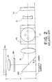
- FIG. 1 is a plan view showing a polarized optical system of the existing optical pickup unit while Fig. 2 is a front view showing the polarized optical system of the existing optical pickup unit.
- the illustrated optical pickup unit uses, as an optical system, a polarized optical system.
- the illustrated optical pickup unit comprises a semiconductor laser (laser diode) LD, a diffraction grating GRT, a beam splitter BS, a collimator lens CL, a rising mirror MIR, a wave plate WP, an objective lens OL, a concave lens (enlargement lens) EL, a photodetector (light receiving element) PD, and a forward sensor FS.
- a reference symbol "Disc" designates an optical disc.
- the semiconductor laser LD radiates a laser beam in the horizontally forward direction.
- the outgoing laser beam is separated into three laser beams by the diffraction grating GRT and is bent at a right angle by the beam splitter BS to go horizontally leftward.
- the beam splitter BS separates the incident laser beam into a reflected beam and a transmitted beam at a constant ratio.
- the beam splitter BS reflects 80% of the incident laser beam as the reflected beam and transmits 20% of the incident laser beam as the transmitted beam.
- the forward sensor FS is also called a front monitor and is for monitoring a light amount of the transmitted beam from the beam splitter BS.
- the laser beam which goes horizontally leftward, is collimated into a collimated beam by the collimator lens CL and thereafter is bent at a right angle by reflection at a reflecting surface of the rising mirror MIR to go vertically upward.
- the laser beam which goes vertically upward, has a polarization direction changed by the wave plate WP and is converged (irradiated) on a signal recording surface of the optical disc Disc through the objective lens OL.
- the wave plate WP may be a half-wave plate or a quarter-wave plate.
- a wave plate WP comprises a transparent plate made of, as a material, a birefringent crystal, such as a quartz crystal. It is known to use, as the wave plate WP, a functional resin or a high-performance resin which is sandwiched between a pair of glass plates.
- a reflected beam goes vertically downward, passes through the objective lens OL, has a polarization direction changed by the wave plate WP, and is bent at a right angle by reflecting at the reflecting surface of the rising mirror MIR to go horizontally rightward.
- the laser beam which goes horizontally rightward, is detected by the photodetector PD through the collimator lens CL, the beam splitter BS, and the concave lens EL.
- the semiconductor laser LD, the beam splitter BS, the collimator lens CL, the rising mirror MIR, and the photodetector PD are disposed above a lower surface of the optical pickup unit (which will be called a pickup's lower surface).
- optical parts such as the semiconductor laser LD, the diffraction grating GRT, the beam splitter BS, the collimator lens CL, the rising mirror MIR, the concave lens EL, the photodetector PD, the wave plate WP, and the forward sensor FS are held in an optical base (not shown).
- the objective lens OL is held by a lens holder (not shown) which is supported to the optical base so as to be slightly movable.
- the pickup's lower surface is a lower surface of the optical base.
- the rising mirror MIR is disposed so that the reflecting surface of the rising mirror MIR is inclined to the pickup's lower surface by 45 degrees.
- a rising or included angle ⁇ between the reflecting surface of the rising mirror MIR and the pickup's lower surface is equal to 45 degrees.
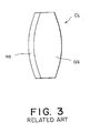
- the collimator lens CL may comprise a glass (a polished lens) GS having one surface and a resin layer RS formed or attached on the one surface of the polished lens GS.
- the collimator lens comprising the polished lens GS alone has a large amount of spherical aberration as it is, and does not suit use as the optical pickup unit.
- a functional lens called a "hybrid lens” is used which comprises the polished lens GS having the one surface on which an aspheric surface made of the resin layer RS is formed.
- a “hybrid lens” in which the resin layer has a function as a spectral filter is disclosed in Japanese Unexamined Patent Publication Tokkai No. Hei 7-56006 or JP-A 7-56006.
- the existing optical pickup unit uses a glass wave plate WP made of the quartz crystal disposed between the rising mirror MIR and the objective lens OL as described above.
- the optical pickup unit with such a structure is moved in a predetermined disc radial direction for the optical disc Disc by a pickup driving portion (not shown). That is, the optical pickup unit is slidably supported on a chassis (not shown) of an optical disc drive. An upper surface of the chassis and the pickup's lower surface are arranged with only a little space left therebetween. Accordingly, it is not preferable that the above-mentioned optical parts are projected downwards below the pickup's lower surface (the lower surface of the optical base). In addition, it is possible to use generally commercially available general-purpose optical parts as the above-mentioned optical parts.
- optical pickup unit In recent years, advances have made the optical disc drive thin. Accompanying this, it is necessary for the optical pickup unit to be made thin.
- "height measure” means a measurement H' between the lower surface of the optical base and a lower surace of the optical disc Disc.
- a light-emitting/receiving unit integrally comprising a semiconductor laser, a photodetector, a diffraction grating, and a hologram element is best used.
- JP-A 10-177733 an included angle between a reflecting surface of reflecting means and a recording surface of an optical recording medium is smaller than 45 degrees.
- a rising mirror has a rising angle smaller than 45 degrees.
- the optical pickup unit using general-purpose optical parts is advantageous in that it is not expensive in comparison with the optical pickup unit using the light emitting/receiving unit. This is because the general-purpose optical parts are not costly.
- the wave plate WP must be disposed between the rising mirror MIR and the objective lens OL, resulting in an increase in number of parts and thus making it difficult to lower the height measure H' of the optical pickup unit. Therefore, as a result, it is difficult to make the optical pickup unit thin, as mentioned in the preamble of the instant specification.
- FIG. 4 is a plan view showing a polarized optical system of the optical pickup unit according to the preferred embodiment of this invention while Fig. 5 is a front view showing the polarized optical system of the optical pickup unit according to the preferred embodiment of this invention.
- the illustrated optical pickup unit is similar in structure and operation to the existing thin optical pickup unit illustrated in Figs. 1 and 2 except that the wave plate WP is omitted from the optical pickup unit and a collimator lens CL(WP) with a wave plate is used in place of the collimator lens CL. Accordingly, components having similar functions of those illustrated in Figs. 1 and 2 are attached with the same reference symbols and description thereof will be omitted in order to simplify description and to avoid repeated description.
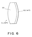
- Fig. 6 schematically illustrates the collimator lens CL(WP) with the wave plate for use in the optical pickup unit illustrated in Figs. 4 and 5.
- the collimator lens CL(WP) with the wave plate comprises a glass (a polished lens) GS having one surface and a functional resin layer RS(WP) attached on the one surface of the glass (polished lens) GS.
- the functional resin layer RS(WP) comprises a resin layer which forms an aspheric surface and which has double refraction and has a function as a half-wave plate or a quarter-wave plate.
- the resin layer RS which is attached on the one surface of the glass (polished lens) GS used as the collimator lens CL shown in Fig. 3, has only the function as the aspheric surface and does not have the double refraction.
- the above-mentioned hybrid lens disclosed in JP-A 7-56006 comprises the resin layer which has the function as the spectral filter and which does not have the function as the wave plate.
- a height measure H of the optical pickup unit is smaller than the height measure H' of the existing optical pickup unit, namely, H ⁇ H'.
- the semiconductor laser LD radiates a laser beam in a horizontally forward direction.
- the radiated laser beam has a polarization direction which extends right and left within a drawing sheet of Fig. 4.
- the outgoing laser beam is separated into three laser beams by the diffraction grating GRT and is bent at a right angle by the beam splitter BS to go horizontally leftward.
- the laser beam, which goes horizontally leftward has a polarization direction which extends up and down within the drawing sheet of Fig. 4.
- the beam splitter BS separates the incident laser beam into a reflected beam and a transmitted beam at a constant ratio.
- the beam splitter BS reflects 80% of the incident laser beam as the reflected beam and transmits 20% of the incident laser beam as the transmitted beam.
- the forward sensor FS monitors a light amount of the transmitted beam from the beam splitter BS.
- the laser beam which goes horizontally leftward, is collimated into a collimated beam and has a polarization direction rotated by the collimator lens CL(WP) with the wave plate and thereafter is bent at a right angle by reflection at the reflecting surface of the rising mirror MIR to go vertically upward.
- the laser beam which goes vertically upward, is converged (irradiated) on a signal recording surface of the optical disc Disc through the objective lens OL.
- a reflected beam goes vertically downward, passes through the objective lens OL, and is bent at a right angle by reflection at the reflecting surface of the rising mirror MIR to go horizontally rightward.
- the return beam which goes horizontally rightward, is detected by the photodetector PD through the collimator lens CL(WP) with the wave plate, the beam splitter BS, and the concave lens EL.
- An optical pickup unit for converging a laser beam produced by a semiconductor laser (LD) on a signal recording surface of an optical disc (Disc) through a polarized optical system, and for detecting a return beam from the signal recording surface by a photodetector (PD) through the polarized optical system.
- the polarized optical system includes a collimator lens (CL(WP)), which comprises a polished lens (GS) having two surfaces, a functional resin layer (RS(WP)) being attached on one of the surfaces of the polished lens.
- the functional resin layer functions as a wave plate.
- Such lens may comprise an objective lens.
Landscapes
- Physics & Mathematics (AREA)
- Optics & Photonics (AREA)
- Optical Head (AREA)
- Polarising Elements (AREA)
Abstract
Description
Claims (8)
- A functional lens (CL(WP)) comprising a polished lens (GS) having two surfaces, wherein a functional resin layer (RS(WP)) functioning as a wave plate extends on one of the two surfaces of said polished lens.
- A functional lens (CL(WP)) as in claim 1, wherein the resin layer (RS(WP)) forms an aspheric surface and produces a double refraction of light.
- A functional lens (CL(WP)) as in claim 2, wherein the lens functions as a half-wave plate or as a quarter-wave plate.
- An optical pickup unit for converging a laser beam produced by a semiconductor laser (LD) on a signal recording surface of an optical disc (Disc) through a polarized optical system, and for detecting a return beam from said signal recording surface by a photodetector (PD) thorugh said polarized optical system, characterized in that said polarized optical system includes the functional lens (CL(WP)) of claim 1.
- An optical pickup unit as claimed in claim 4, wherein said functional lens comprises a collimator lens (CL(WP)).
- An optical pickup unit as claimed in claim 4, wherein said functional lens comprises an objective lens (OL).
- An optical pickup unit as in any one of claims 4, 5 and 6, wherein the resin layer (RS(WP)) forms an aspheric surface and produces a double refraction of light.
- An optical pickup unit as in claim 7, wherein the functional lens functions as a half-wave plate or a quarter-wave plate.
Applications Claiming Priority (2)
| Application Number | Priority Date | Filing Date | Title |
|---|---|---|---|
| JP2001090762 | 2001-03-27 | ||
| JP2001090762A JP2002288872A (en) | 2001-03-27 | 2001-03-27 | Optical pickup device |
Publications (2)
| Publication Number | Publication Date |
|---|---|
| EP1251497A2 true EP1251497A2 (en) | 2002-10-23 |
| EP1251497A3 EP1251497A3 (en) | 2004-05-26 |
Family
ID=18945502
Family Applications (1)
| Application Number | Title | Priority Date | Filing Date |
|---|---|---|---|
| EP02252246A Withdrawn EP1251497A3 (en) | 2001-03-27 | 2002-03-27 | Thin optical pickup unit, and lens therefor |
Country Status (2)
| Country | Link |
|---|---|
| EP (1) | EP1251497A3 (en) |
| JP (1) | JP2002288872A (en) |
Family Cites Families (4)
| Publication number | Priority date | Publication date | Assignee | Title |
|---|---|---|---|---|
| JP3292219B2 (en) * | 1993-09-01 | 2002-06-17 | 日本電信電話株式会社 | Divided wave plate and manufacturing method thereof |
| JPH087327A (en) * | 1994-06-23 | 1996-01-12 | Kenwood Corp | Optical pickup device |
| JP3399129B2 (en) * | 1994-12-21 | 2003-04-21 | ミノルタ株式会社 | Refractive index distribution type aspherical lens |
| JP2001076865A (en) * | 1999-09-08 | 2001-03-23 | Toyota Motor Corp | Organic EL device and manufacturing method thereof |
-
2001
- 2001-03-27 JP JP2001090762A patent/JP2002288872A/en not_active Withdrawn
-
2002
- 2002-03-27 EP EP02252246A patent/EP1251497A3/en not_active Withdrawn
Also Published As
| Publication number | Publication date |
|---|---|
| EP1251497A3 (en) | 2004-05-26 |
| JP2002288872A (en) | 2002-10-04 |
Similar Documents
| Publication | Publication Date | Title |
|---|---|---|
| EP0727777B1 (en) | Optical pickup device | |
| RU2155389C2 (en) | Design of optical detector, lens, and optical interface device | |
| US5777973A (en) | Reproducing and recording optical pickup compatible with discs having different thicknesses | |
| EP1130582B1 (en) | Semiconductor laser device and optical pickup device using the same | |
| US5703862A (en) | Dual focus objective lens with two curvatures for focussing light on two different kinds of disks with different thicknesses | |
| RU98102710A (en) | OPTICAL SENSOR (OPTIONS), LENS (OPTIONS) AND OPTICAL ADAPTER DEVICE (OPTIONS) | |
| US7558179B2 (en) | Compatible optical pickup using light sources following a common optical path | |
| CA2278416A1 (en) | Catadioptric optical system, optical pickup and optical disk drive employing the same, and optical disk | |
| KR19990080234A (en) | Optical pickup with catadioptric objectives | |
| US5737295A (en) | Dual-focus optical pickup for different thicknesses of recording medium | |
| KR100813945B1 (en) | Optical pickup device and recording medium applied thereto | |
| US6115349A (en) | Two laser source optical pickup with a plano-convex lens to compensate for aberration caused by discs of different thicknesses | |
| KR20030078654A (en) | Optical pickup apparatus and optical disk apparatus therefor | |
| KR100421045B1 (en) | Slim optical pickup apparatus | |
| JP2003272220A (en) | Optical pickup device | |
| US7619960B2 (en) | Optical pickup device | |
| EP1761921B1 (en) | Apparatus and method for generating a scanning beam in an optical pickup head, miniature optical pickup head and optical storage system incorporating a miniature pickup head | |
| EP1184857A2 (en) | Optical pickup unit | |
| EP1016080B1 (en) | Optical spot generation device for recording medium | |
| KR100595517B1 (en) | Optical pickup module | |
| US20090059770A1 (en) | Optical pickup apparatus | |
| JP2002288872A (en) | Optical pickup device | |
| JP2006505090A (en) | Optical scanning device | |
| KR20040063034A (en) | Recordable optical pickup | |
| CN101322185A (en) | optical pickup device |
Legal Events
| Date | Code | Title | Description |
|---|---|---|---|
| PUAI | Public reference made under article 153(3) epc to a published international application that has entered the european phase |
Free format text: ORIGINAL CODE: 0009012 |
|
| AK | Designated contracting states |
Kind code of ref document: A2 Designated state(s): AT BE CH CY DE DK ES FI FR GB GR IE IT LI LU MC NL PT SE TR |
|
| AX | Request for extension of the european patent |
Free format text: AL;LT;LV;MK;RO;SI |
|
| PUAL | Search report despatched |
Free format text: ORIGINAL CODE: 0009013 |
|
| AK | Designated contracting states |
Kind code of ref document: A3 Designated state(s): AT BE CH CY DE DK ES FI FR GB GR IE IT LI LU MC NL PT SE TR |
|
| AX | Request for extension of the european patent |
Extension state: AL LT LV MK RO SI |
|
| RIC1 | Information provided on ipc code assigned before grant |
Ipc: 7G 02B 1/10 B Ipc: 7G 11B 7/135 B Ipc: 7G 11B 7/00 A |
|
| AKX | Designation fees paid | ||
| REG | Reference to a national code |
Ref country code: DE Ref legal event code: 8566 |
|
| STAA | Information on the status of an ep patent application or granted ep patent |
Free format text: STATUS: THE APPLICATION IS DEEMED TO BE WITHDRAWN |
|
| 18D | Application deemed to be withdrawn |
Effective date: 20041127 |