TECHNICAL FIELD OF THE INVENTION
-
The present invention relates to the contrast adjusting circuit for the
displays such as the PDP using the PDP (Plasma Display Panel) or the like.
BACKGROUND ART
-
Conventionally, this kind of contrast adjusting circuit is composed of a
multiplying circuit 10 as is shown in Fig. 1, the multiplying circuit 10 being
designed to obtain the output video data Y by multiplying the video data X by
a variably set slope A.
-
When input video data X and the output video data Y are represented by X
(X>=0) and Y (Y>=0) of the X-Y coordinates, there holds a relationship, Y =
A X, an expression representing a strait line A including the origin (0, 0),
between the input video data X and the output video data Y as shown in Fig. 2.
That is, assuming that the variable range of the slope A to be from A1 to Am
(A1 =< A =< Am, m being an integer 2 or more), the contrast increases when
the slope A is increased (e.g., Y = Am X), whereas the contrast decreases
when the slope A is decreased (e.g., Y = A1 · X).
-
However, in the case of the prior art as is shown in Fig. 1 there occurs a
problem such that, when the contrast is set to a high level by setting the slope
A to a high level (e.g., A = Am), the luminance of the image corresponding to
low-level input video data X (i.e., low input level) becomes too high causing
the image to become whitish.
-
Another problem of the prior art has been that the optimal contrast
adjustment cannot be made to the ever-changing condition of the image.
-
The present invention is made in consideration of the problem of the prior
art and is first intended to provide a contrast adjusting circuit capable of
controlling the increase in low-level luminance at the time when the contrast
is increased, thereby preventing the image from becoming whitish.
-
The second object of the present invention is to provide a contrast
adjusting circuit capable of adjusting the contrast to an optimal level
corresponding to the ever-changing condition of the image.
DISCLOSURE OF THE INVENTION
-
The contrast adjusting circuit according to claim 1 comprises a video data
calculating section designed to obtain the output video data by substituting
the input video data X, the slope A and the central point data Xc and Yc in the
calculation formula, Y = A · X + Yc - A · Xc respectively, where X (X>=0) of
the X-Y coordinate system is the input video data; Y (Y>=0) is the output
video data with adjusted contrast; A(A>0) is the variably set contrast
adjusting slope; Xc and Yc (Xc>0, Yc>0) are the central point data.
-
In such a system, the calculation formula Y = A · X + Yc - A · Xc to be
applied to the operation of the video data calculating section produces a
straight line passing through the points (Xc, Yc) within the first quadrant
(Xc>0, Yc>0) not including the origin (0, 0) of the X-Y coordinates.
Therefore, when the slope A, the slope for adjusting the contrast, is increased
to increase the contrast, the rise of the output video data Y corresponding to
the low level of the input video data X can be prevented, unlike the case of
the prior art represented by the calculation formula, Y = A · X, which
produces a slope passing through the origin (0, 0), thereby preventing the
image from becoming whitish.
-
Differing from the invention according to claim 1, in the invention
according to claim 2, in order to enable the contrast to be adjusted according
to the average luminance level of each image, there are provided the average
luminance calculating section, for obtaining the average luminance level of
the images during the n-frame period (n being the integer 1 or more), and the
data converting section, for converting the average luminance level to the
corresponding central point data, Xc and Yc, out of a plurality of
predetermined central point data, so that such central point data, Xc and Yc,
can be used as the central point data in the video data calculating section.
-
In other words, since the output video data Y, corresponding to the
average luminance level of the n frame images, can be obtained by the
calculation formula, Y = A · X + Yc - A · Xc, the contrast can be adjusted
according to the level of the average luminance of the image.
-
Differing from the invention according to claim 1 or claim 2, in the
invention according to claim 3, in order to simplify the composition of the
video data calculating section, the video data calculation section comprises
the subtracting circuit for subtracting the central point data Xc from the input
video data X, the multiplying circuit for multiplying the output data of the
subtracting circuit by the slope A, and the adding circuit for adding the
central point data Yc to the output data of the multiplying circuit to thereby
obtain the output video data Y.
-
Differing form the invention according to claim 1, in the invention
according to claim 4, the central point data, Xc and Yc, are given as the data
on the basis of Y = X, and the video data calculating section is designed to
obtain the video data Y by using the calculation formula, Y = A ·X + Xc ·
(1 - A), which is introduced by setting Yc = Xc in the calculation formula, Y
= A · X + Yc - A · Xc. In this method, in all the cases where the slope A for
the adjustment of contrast is 1 or more, the rise of the (luminance of) the
output video data Y at the low levels of input video data X can be prevented.
In other words, (the line represented by) Y = A · X + Xc · (1 - A), which is
introduced by setting Yc = Xc in the calculation formula, Y = A · X + Yc - A
· Xc, passes through the point represented by Y = X, so that, when A is 1 or
more, the value of Xk representing the X-coordinate value of intersection (Xk,
0) between the straight line X and the straight line Y becomes larger than 1,
thereby not only enabling the Y-coordinate values, corresponding to X-coordinate
values ranging from 0 to Xk to be made 0 but also enabling the
value of Y can be made smaller than that by the prior art even when the value
of X is larger than Xk.
-
Differing from the invention according to the claim 4, in the invention
according to claim 5, in order to enable the contrast to be adjusted according
to the level of the average luminance of each image, the average luminance
calculating section, for obtaining the average luminance level of the images
during the n-frame period on the basis of the input video data X, and the data
converting section, for converting the average luminance level, which is
obtained by the average luminance calculating section, to the corresponding
central point data, Xc and Yc, out of a plurality of predetermined central
point data, whereby the central point data, Xc and Yc, which are outputted
from the data converting section, are processed by the video data calculating
section.
-
In other words, the central point data, Xc and Yc, which are to be
processed by the video data calculating section, undergoes the contrast
adjustment as being the data corresponding to the average luminance level of
the n-frame images.
-
Differing from the invention according to claim 4 or claim 5, in the
invention according to claim 6, in order to simplify the composition of the
video data calculating section, the video data calculating section comprises
the first multiplying circuit, for multiplying the input video data by the slope
A, the subtracting circuit, for subtracting the slope A from the constant 1, the
second multiplying circuit for multiplying the output data of the subtracting
circuit by the central point data Xc, and the adding circuit for adding the
output data of the first multiplication circuit to the output data of the second
multiplying circuit to thereby obtain the output video data Y.
-
Differing from the inventions according to claim 1, claim 2 or claim 3, in
the inventions according to claim 7 and claim 8, in order to simplify the
composition of the data converting section, the data converting section
comprises the look-up table, which outputs the corresponding central point
data, Xc and Yc, by using the average luminance, which is obtained by the
average luminance calculating section, as the address.
-
Differing from the invention according to claim 4, claim 5 or claim 6, in
the inventions according to claim 9 and claim 10, in order to simplify the
composition of the data converting section, the data converting section
comprises the look-up table which is designed to output the corresponding
central point data Xc by using as the address the average luminance obtained
by the average luminance calculating section.
BRIEF DESCRIPTION OF DRAWINGS
-
- Figure 1 is a block diagram illustrating the prior art.
- Figure 2 is a diagram illustrating the function of the system illustrated in
Figure 1, and is also an input/output characteristic diagram indicating the
relationship between X and Y.
- Figure 3 is a block diagram illustrating the contrast adjusting circuit as
the first embodiment of the present invention.
- Figure. 4 is a characteristic diagram illustrating the function of the system
illustrated in Fig. 3, and is also an input/output characteristic diagram
illustrating the relationship of X and Y where the central point data Xc and
Yc are the coordinates of Y = X; APL is constant; and A is variable.
- Figure 5 is a characteristic diagram illustrating the function of the system
illustrated in Fig. 3 and is also an input/output characteristic diagram
illustrating the relationship between X and Y where the central point data (Xc,
Yc), (Xc1, Yc1) and (Xcm, Ycm) are on the coordinates of Y = X; A, larger
than 1, is constant; and the relationship between X and Y where the APL is
variable.
- Figure 6 is a characteristic diagram illustrating the function of the system
shown in Fig. 3, and is also an input/output characteristic diagram indicating
that the central point data (Xc, Yc), (Xc1, Yc1 and (Xcm, Ycm) are
represented by coordinates of Y = X, and that A which is smaller than 1 is
constant, while the APL is variable.
- Figure 7 is a characteristic diagram illustrating the function of the system
shown in Fig. 3, and is also an input/output characteristic diagram showing
the case where the central point data (Xc, Yc), (Xc1, Yc1) and (Xcm, Ycm)
are represented by Y = aX + b where APL is constant while A is variable, and
the case where the central point data, (Xc, Yc), (Xc1, Yc1 and (Xcm, Ycm)
are represented by Y = aX + b where A is a constant value larger than 1 while
APL is variable.
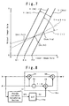
- Figure 8 is a block diagram showing the contrast adjusting circuit as the
second embodiment of the present invention.
-
BEST MODE OF CARRYING OUT THE INVENTION
-
The embodiments of the present invention will be described referring to
the drawing.
-
Fig. 3 shows a contrast adjusting circuit as the first embodiment of the
present invention. In Fig. 3, reference numeral 12 represents the average
luminance calculating section; 14, the LUT (Look Up Table) as an example of
the data converting section; 16, the video data calculating section.
-
As described later, on the X - Y coordinates, the X (X>=0) is the input
video data; the Y(Y>=0) is the output video data whose contrast has been
adjusted; A (A>0) is a predetermined variable slope for the adjustment of the
contrast.
-
The average luminance calculating section 12 determines the average
picture level (hereinafter referred to as APL) of the images of n-frame period
(n being the integer larger than 1, e.g, n = 1) on the basis of input video data
X.
-
The LUT 14 outputs the corresponding central point data, Xc and Yc
(Xc>0, Yc>0), out of a plurality of predetermined central point data on the
coordinates of Y = X.
-
The video data calculating section 16 substitutes the input video data X,
the slope A and the central point data (Xc, Yc) in the calculation formula Y =
A · X + Yc - A · Xc to calculate the output video data Y.
-
The above video data calculating section 16 comprises the subtracting
circuit 18, for subtracting the central point data Xc from the input video data
X, the multiplying circuit 20, for multiplying the output data of the
subtracting circuit 18 by the slope A, and the adding circuit 22, for adding
the central point data Yc to the output data of the multiplying circuit 20 to
generate the output video data Y.
-
Next, the function of the system illustrated in Fig. 3 will be described
referring to Figs. 4 through 7.
- (1) When the input video data X is inputted to the average luminance
calculating section 12, the average luminance calculating section 12
determines the APL of the images during n frame period (e.g., 1 frame
period) on the basis of the input video data X.
- (2) When the APL, obtained by the average luminance calculating section
12 is inputted to the LUT 14, the corresponding central point data Xc and Yc
are outputted out of a plurality of predetermined central point data
represented by the coordinates of Y = X by using the APL as the addresses.
- (3) The video data calculating section 16 obtains the output video data Y
by substituting the central point data, Xc and Yc, outputted from the LUT 14,
in the calculation formula, Y = A · X + Yc - A · Xc, for each pixel (e.g., for
each dot) during n-frame period, by using the input video data X, the set
slope A and the APL of the immediately preceding n-frame image as
addresses.
In other words, Xc is subtracted from X in the subtracting circuit 18; the
output data from the subtracting circuit 18 is multiplied by A in the
multiplying circuit 20; Yc is added to the output data A · (X - Xc) of the
multiplying circuit 20 in the adding circuit 22; the obtained data {A · (X -
Xc) + Yc} represents Y.
- (4) When the slope A is varied for a image who se APL is constant, e.g.,
when the user varied A within the range of A1 to Am by varying the
resistance value for contrast adjustment, the contrast can be adjusted along
the straight line, Y(1) - Y(M) within the range indicated by arrows in Fig. 4.
- (4-1) When A is set larger than 1 (e.g., A = Am) to raise the contrast, the
relationship between X and Y, for instance, becomes like Y(M) in Fig. 4.
The Y(M) represents the straight line, Y(M) = Am · X + Yc - Am · Xc, which
is obtained by substituting Am for the A in Y = A · X + Yc - A · Xc.
Therefore, regardless of the values of the central point data, Xc and Yc, in
the first quadrant of the X-Y coordinate system where Y = X, the Xk of the
intersection (Xk, 0)between the straight line Y (M) and the X-axis, becomes
larger than 0 as shown in Fig. 4; when the X ranges from 0 to Xk, Y can be set
to 0; even when X is larger than Xk, the value of Y can be set smaller than
that in the case of the prior art (Y = Am · X).
In consequence, not only the rise of the luminance of the lower level at
the time when the contrast is raised thereby to prevent the image from
becoming whitish but also the contrast can be adjusted corresponding to the
APL of each image.
- (4-2) When A is set smaller than 1 (e.g., A = A1), the relationship
between X and Y becomes, for instance, as Y(1) in Fig. 4. This Y(1)
represents the straight line Y (1) = A1 · X + Yc - A1 · Xc, where A1 is
substituted for A in Y = A · X + Yc - A · Xc.
- (5) When, after raising the contrast by setting A larger than 1 (e.g., A =
Am), A is set constant, and the APL is made to vary within the range where
the APL is APL1 or more but APLm or less, the contrast is adjusted along the
straight lines, Y (M1) - Y (Mm), within the range indicated by arrows in Fig.
5.
- (5-1) When the level of the APL is relatively high (e.g., APL = APLm),
the relation between X and the Y becomes Y (Mm) as is shown in Fig. 5. This
Y(Mm) represents a straight line, Y(Mm) = Am · X + Ycm - Am · Xcm, where
Am is substituted for, and Xcm and Ycm are substituted for Xc and Yc in Y =
A · X + Yc - A · Xc. In this case, Xcm and Ycm represent the data outputted
form the LUT14 by using the APLm as address.
- (5-2) Where the value of the APL is relatively small (e.g., APL = APL1),
the relationship between X and Y becomes Y (M1) in Fig. 5. This Y(M1)
represents a straight line, Y (M1) = Am · X + Yc1 Am · Xc1 introduced by
substituting Am for A, while substituting Xc1 and Yc1 for Xc and Yc, in Y =
A · X + Yc - A · Xc. In this case, Xc1 and Yc1 represent the data outputted
from the LUT14 by using the APL1 as the address.
- (5-3) Therefore, as shown in Fig. 5, the values, X1, Xk and Xm of the
intersections, (X1,0), (Xk,0), (Xm, 0) of the straight lines, Y (M1), Y (M)
and Y (Mm) to the X-axis are respectively larger than 0, so that, where the
value of X is within the range of 0, X1, Xk and Xm, the value of Y can be set
to 0 where the value of X is within 0, X1, Xk and Xm, and the value of Y can
be made smaller than that in the case of the prior art even when the value of X
is X1 or more, Xk or more and Xm or more.
In consequence, not only the rise of the luminance for lower level at the
time when the contrast is raised can be prevented to prevent the image from
becoming whitish but also the contrast of each image can be adjusted
according to the APL of each image.
- (6) Further, when, after setting A smaller than 1 (e.g., A = A1) to lower
the contrast, and then A is set constant, and when the APL is varied within a
range, which is APL1 or more and APLm or less, the contrast is adjusted
within the range indicated by arrows and along the straight lines, Y (11)
through Y (1m) in Fig. 6.
- (6-1) When the value of APL is relatively high (e.g., APL = APLm), the
relationship of X and Y becomes Y (1m) as shown in Fig. 6. This Y (1m)
represents the straight line Y (1m) = A1 · X + Ycm - A1 · Xcm introduced by
substituting A1 for A, and Xcm and Ycm for Xc and Yc in Y = A · X + Yc - A
· Xc.
- (6-2) When APL is relatively small (e.g., APL = APL1), the relationship
of X and the Y becomes as represented by Y (11) in Fig. 6. This Y (11)
represents a straight line Y (11) = A1 · X + Yc1 - A1 · Xc1, introduced by
substituting A1 for A and Xc1 and Yc1 for Xc and Yc in Y = A · X + Yc - A ·
Xc.
- (6-3) Thus, it is possible to adjust the contrast according to the APL of
each image.
-
-
In the embodiment of the present invention shown in Fig. 3, the system is
designed so that the central point data, Xc and Yc, outputted from the LUT14
correspond to the values represented by Y = X (i.e., Yc = Xc) by using the
APL as the address, but the present invention is not limited to this
embodiment. For instance, as shown in Fig. 7, the present invention is also
applicable to the case where the system is designed so that the central point
data, Xc and Yc, outputted from the LUT 14 by using the APL as the address,
are set as being the values represented by Y = a · X + b (i.e., Yc = a · Xc + b).
In this case, a and b represent the properly set constants respectively.
-
For instance, when the APL is kept constant while A is varied, as shown
in Fig. 7, the contrast is adjusted within the range indicated by the arrows
followed by a dot-and-dash line and along the straight line, Y (1) through the
straight line Y (M).
-
Therefore, when A is increased to 1 or more (e.g., A = Am) to raise the
contrast, the relationship between X and Y is represented by the solid line Y
(M) in Fig. 7. Even when the central point data, Xc and Yc, are represented
by Y = aX + b, the value of the intersection Xk (Xk, 0) between the straight
line Y (M) and X-axis becomes larger than 0 within the range of A>1. That is,
similarly to the case shown in Fig. 4, where X ranges from 0 to Xk, Y can be
set to 0, and further even where X is Xk or more, the value of Y can be made
smaller than that in the case of the prior art.
-
Therefore, not only the rise of the luminance at low levels at the time
when the contrast is raised can be prevented thereby to prevent the image
from becoming whitish but also the contrast can be adjusted according the
APL of each image.
-
Further, when A is set constant as being a value larger than 1 (e.g., A =
Am) while letting the APL vary (APL1 =< APL =< APLm), the contrast can
be adjusted, for instance, along the straight lines, Y (M1), Y(M) and Y (Mm),
based on the central point data, (Xc1, Yc1), (Xc, Yc) and (Xcm, Ycm) which
are represented by Y = a · X + b.
-
Thus, when the APL is given as APL1, APLk or APLm, the relationship
between X and Y are represented by Y (M1), Y (M) and Y (Mm) shown in Fig.
7, and, even when the central point data, (Xc1, Yc1), (Xc, Yc), (Xcm, Ycm)
are represented by Y = aX + b, the values, X1, Xk and Xm at the intersections,
(X1, 0), (Xk, 0), (Xm, 0), of the straight lines, Y (M1), Y (M) and Y (Mm),
and the X-axis, become larger than 0. In other words, similarly to the case
shown in Fig. 5, where the value of X is given as 0, X1, Xk or Xm, Y can be
made 0; even when the value of the X is larger than X1, Xk or Xm, the value
of Y can be made smaller than that in the case of the prior art.
-
In consequence, even if the contrast is raised, the rise of the luminance at
low level can be prevented, thereby not only preventing the image from
becoming whitish but also enabling the contrast to be adjusted according to
the APL of each image.
-
Fig. 8 shows the contrast adjusting circuit as the second embodiment of
the present invention, which is made available by replacing the LUT14 and
the video data calculating section 16 of the first embodiment with the
LUT14a and the video data calculating section 16a, which will be described
later.
-
In Fig. 8, the descriptions of those reference numerals similar to those in
Fig. 3 will be omitted as being those for similar parts.
-
In Fig. 8, 14a represents the LUT as an example of data converting
section, and 16a represents an image data calculating section.
-
The LUT14a outputs a corresponding central point data Xc, out of a
plurality of predetermined central point data represented by the X-Y
coordinate system for Y = X, by using, as the address, the APL determined by
the average luminance calculating section 12.
-
The video data calculation section 16a calculates the output video data Y
by substituting the input video data X, slope A and central point data X in the
calculation formula, Y = A · X + Xc (1 - A). This video data calculating
-section 16a performs the calculation, which is equivalent to the calculation
by the calculation formula Y = A · X + Yc - A · Xc where Yc = Xc.
-
More specifically, the video data calculating section 16a comprises the
first multiplying circuit 24, for multiplying the input video data X by the
slope A, the subtracting circuit 26, for subtracting the slope A from constant
1, the second multiplying circuit, for multiplying the output data of the
subtracting circuit 26 by the central point data Xc, and the adding circuit 30
for adding the output data of the first multiplying circuit 24 and the output
data of the second multiplying circuit 28 to produce the output video data Y.
-
Next, the function of the system illustrated in Fig. 8 will be described
referring to Figs. 4 through 6.
- (1) Upon input of the video data X to the average luminance calculating
section 12, the APL of the image for n-frame period (e.g., 1 frame period) is
obtained by the average luminance calculating section 12 on the basis of the
input video data X.
- (2) Upon input of the APL, obtained by the average luminance calculating
section 12, to the LUT14a, the corresponding central point data Xc, out of a
plurality of predetermined central point data represented by the X-Y
coordinate system for Y = X, is outputted from the LUT14a.
- (3) During the n-frame period, the video data calculating section 16a
obtains the output video data Y for each pixel (e.g., for each dot) by
substituting the input video data X, set slope A, the central point data Xc,
outputted from the LUT14a, in the calculation formula, Y = A · X + Xc · (1 -
A) by using, as an address, the APL of the immediately preceding n-frame
image.
In other words, X is multiplied by the slope A in the first multiplying
circuit 24; A is subtracted from the constant 1 in the subtracting circuit; the
output data (1 - A) of the subtracting circuit 26 is multiplied by Xc in the
second multiplying circuit; the output data {Xc · (1 - A)} of the second
multiplying circuit 28 is added to the output data A · X of the first
multiplying circuit 24 by the adding circuit 30, and the obtained data, {A · X
+ Xc · (1 - A)} is treated as Y.
- (4) In the case of an image whose APL is constant, when the slope A is
varied, similarly to the case of the embodiment given in Fig. 3, the contrast is
adjusted within the range indicated by the arrows and along the straight lines
Y (1) through Y (M).
In other words, when the contrast is raised by increasing the value of A
which is variable within A1 and Am, the relationship between X and Y is
represented, for example, by Y (M) in Fig. 4, whereby the luminance at low
levels can be prevented from rising to prevent the image from becoming
whitish, while enabling the contrast to be adjusted matching with the APL of
each image.
- (5) When A is set larger than 1 (e.g., A = Am) and constant, while setting
APL (APL1 =< APL =< APLm) variable, the contrast can be adjusted within
the range indicated by arrows and along the straight lines Y (M1) through Y
(Mm) as shown in Fig. 5. In other words, the relationship between X and Y
becomes as represented by Y (Mm) in Fig. 5 when the value of APL is
relatively large, and it becomes as represented Y (M1) in the same figure
when the value of APL is relatively small. Therefore, when the contrast is
raised, not only the rise of the luminance at low levels can be prevented to
prevent the image from becoming whitish but also the contrast can be
adjusted matching with the APL of each image.
- (6) When A is set smaller than 1 (e.g., A = A1) and constant, while the
APL (APL1 =< APL =< APLm) is set variable, the contrast is adjusted within
the range indicated with arrows and along the straight lines Y (11) though Y
(1m) as in Fig. 6.
-
-
In other words, the relationship between X and Y becomes like Y (1m) in
Fig. 6 when the value of APL is relatively large, while the same becomes like
Y (11) in the same figure when the APL is relatively small, thereby enabling
the contrast to be adjusted matching with the APL of each image.
-
In each of the embodiments shown in Fig. 3 and Fig. 8, the data
converting section is composed of the LUT in order to simplify the
composition of the data converting section. The present invention, however,
is not limited to these embodiments, and thus the data converting section may
be one capable of converting the average luminance, obtained by the average
luminance calculating section, to Xc and Yc (Xc>0, Yc>0) out of a plurality
of predetermined central point data represented by the X-Y coordinate system,
or one capable of converting the average luminance, obtained by the average
luminance calculating section, to the corresponding central point data Xc
(Xc>0) out of a plurality of predetermined central point data represented by
the X-Y coordinate system.
-
In those previously described embodiments shown in Fig. 3 and Fig. 8, in
order for the contrast to be adjusted according to the average luminance level
of each image, there are provided the average luminance calculating section,
designed to obtain the average luminance level of the images during the n-frame
period based on the input video data X, and the data converting section,
designed to convert the average luminance level to corresponding central
point data Xc, Yc or Xc out of a plurality of predetermined central point data.
The present invention, however, is not limited to these embodiments. That
is, the present invention is also applicable to the case where the average
luminance calculating section and the data converting section are omitted so
that the central point data, Xc, Yc or Xc to be used in the video data
calculating section is set separately just like the case of the slope A.
INDUSTRIAL APPLICABILITY
-
As discussed in the foregoing, the contrast adjusting circuit according to
the present invention is designed so that the rise of the luminance at low
levels is prevented-to prevent the image to become whitish when the contrast
is raised. The present invention is also applicable for making optimal
adjustment of the contrast coping with ever-changing condition of the image.