EP1251411A2 - Double-sided image forming device having a turntable guide guiding a rear end of a large-size sheet - Google Patents
Double-sided image forming device having a turntable guide guiding a rear end of a large-size sheet Download PDFInfo
- Publication number
- EP1251411A2 EP1251411A2 EP02008126A EP02008126A EP1251411A2 EP 1251411 A2 EP1251411 A2 EP 1251411A2 EP 02008126 A EP02008126 A EP 02008126A EP 02008126 A EP02008126 A EP 02008126A EP 1251411 A2 EP1251411 A2 EP 1251411A2
- Authority
- EP
- European Patent Office
- Prior art keywords
- double
- rear end
- image forming
- end guide
- operation unit
- Prior art date
- Legal status (The legal status is an assumption and is not a legal conclusion. Google has not performed a legal analysis and makes no representation as to the accuracy of the status listed.)
- Granted
Links
Images





Classifications
-
- G—PHYSICS
- G03—PHOTOGRAPHY; CINEMATOGRAPHY; ANALOGOUS TECHNIQUES USING WAVES OTHER THAN OPTICAL WAVES; ELECTROGRAPHY; HOLOGRAPHY
- G03G—ELECTROGRAPHY; ELECTROPHOTOGRAPHY; MAGNETOGRAPHY
- G03G15/00—Apparatus for electrographic processes using a charge pattern
- G03G15/22—Apparatus for electrographic processes using a charge pattern involving the combination of more than one step according to groups G03G13/02 - G03G13/20
- G03G15/23—Apparatus for electrographic processes using a charge pattern involving the combination of more than one step according to groups G03G13/02 - G03G13/20 specially adapted for copying both sides of an original or for copying on both sides of a recording or image-receiving material
- G03G15/231—Arrangements for copying on both sides of a recording or image-receiving material
- G03G15/232—Arrangements for copying on both sides of a recording or image-receiving material using a single reusable electrographic recording member
- G03G15/234—Arrangements for copying on both sides of a recording or image-receiving material using a single reusable electrographic recording member by inverting and refeeding the image receiving material with an image on one face to the recording member to transfer a second image on its second face, e.g. by using a duplex tray; Details of duplex trays or inverters
-
- G—PHYSICS
- G03—PHOTOGRAPHY; CINEMATOGRAPHY; ANALOGOUS TECHNIQUES USING WAVES OTHER THAN OPTICAL WAVES; ELECTROGRAPHY; HOLOGRAPHY
- G03G—ELECTROGRAPHY; ELECTROPHOTOGRAPHY; MAGNETOGRAPHY
- G03G15/00—Apparatus for electrographic processes using a charge pattern
- G03G15/65—Apparatus which relate to the handling of copy material
- G03G15/6588—Apparatus which relate to the handling of copy material characterised by the copy material, e.g. postcards, large copies, multi-layered materials, coloured sheet material
- G03G15/6594—Apparatus which relate to the handling of copy material characterised by the copy material, e.g. postcards, large copies, multi-layered materials, coloured sheet material characterised by the format or the thickness, e.g. endless forms
-
- G—PHYSICS
- G03—PHOTOGRAPHY; CINEMATOGRAPHY; ANALOGOUS TECHNIQUES USING WAVES OTHER THAN OPTICAL WAVES; ELECTROGRAPHY; HOLOGRAPHY
- G03G—ELECTROGRAPHY; ELECTROPHOTOGRAPHY; MAGNETOGRAPHY
- G03G2215/00—Apparatus for electrophotographic processes
- G03G2215/00362—Apparatus for electrophotographic processes relating to the copy medium handling
- G03G2215/00443—Copy medium
- G03G2215/00451—Paper
- G03G2215/00464—Non-standard format
- G03G2215/00468—Large sized, e.g. technical plans
-
- G—PHYSICS
- G03—PHOTOGRAPHY; CINEMATOGRAPHY; ANALOGOUS TECHNIQUES USING WAVES OTHER THAN OPTICAL WAVES; ELECTROGRAPHY; HOLOGRAPHY
- G03G—ELECTROGRAPHY; ELECTROPHOTOGRAPHY; MAGNETOGRAPHY
- G03G2215/00—Apparatus for electrophotographic processes
- G03G2215/00362—Apparatus for electrophotographic processes relating to the copy medium handling
- G03G2215/00535—Stable handling of copy medium
- G03G2215/0054—Detachable element of feed path
Definitions
- the present invention generally relates to a double-sided image forming device, and more particularly, to a double-sided image forming device, such as a copying machine, a printer, or a facsimile-apparatus, having a double-side operation unit that forms an image on a sheet fed thereto, and reverses the sheet so as to cause an image to be formed on a reverse side.
- a double-sided image forming device such as a copying machine, a printer, or a facsimile-apparatus
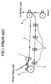
- FIG.1 is an illustration outlining the double-side operation unit included in the conventional double-sided image forming device.
- a sheet having an image formed on one side enters from a fixing unit of an image forming unit provided in a body of the image forming device into a sheet reversing unit of the double-side operation unit.
- the sheet is temporarily contained in a switchback conveying path 2 via a reversibly rotatable switchback roller 1.
- the switchback roller 1 rotates reversely so as to send the sheet to a reverse roller 3.
- the reverse roller 3 turns the sheet by 180° toward a horizontal conveying path (a reconveying path) 5 provided underneath.
- the horizontal conveying path 5 comprises a plurality of horizontal conveying rollers 4 arranged at intervals corresponding to a length of a minimum-size sheet, and transfers the sheet to a relay roller 6 provided further downstream. Then, the sheet returns to the image forming unit provided in the body of the image forming device so that an image is formed on the other side of the sheet.
- FIG.2A and FIG.2B are illustrations explaining the operation of conveying a maximum-size sheet in a conventional double-side operation unit.
- the switchback conveying path 2 has a length L smaller than a length L Pmax of the maximum-size sheet so that the body of the image forming device occupies little space.
- a rib 7 is provided as shown in FIG.2B so as to bring a rear end of the sheet to a refuge space upward.
- a more specific object of the present invention is to provide a double-sided image forming device which can minimize a space occupied by a double-side operation unit by adopting simple structures so that the double-sided image forming device occupies little space (is thinned down).
- a double-sided image forming device comprising a double-side operation unit including a switchback conveying path having a length smaller than a length of a maximum-size sheet, and a movable rear end guide guiding a rear end of a large-size sheet.
- a space occupied by the double-side operation unit upon being drawn out from a body of the double-sided image forming device can be reduced. Consequently, the double-sided image forming device occupies little space.
- the rear end guide is turnable in accordance with a drawing and a setting of the double-side operation unit.
- a turning angle of the rear end guide is determined by a positioning member provided on a board of the body of the double-sided image forming device and a stopper provided on a side surface of the double-side operation unit. This simple arrangement enables the double-sided image forming device to occupy little space.
- the turning angle of the rear end guide can be varied continuously by indefinite steps by mounting a dial member on a turning axle of the rear end guide and providing a conical stopper on the side surface of the double-side operation unit.
- the present arrangement eliminates variations in dimensional tolerances of components composing the double-sided image forming device so as to realize an optimal sheet conveyance in the double-sided image forming device.
- FIG.3 is an illustration outlining a double-side operation unit included in a double-sided image forming device according to the present invention.
- the double-side operation unit according to the present invention comprises the switchback roller 1, the switchback conveying path 2, the reverse roller 3, the horizontal conveying rollers 4, the horizontal conveying path 5, and the relay roller 6, as does the conventional double-side operation unit shown in FIG.1.
- the double-side operation unit according to the present invention performs the same sheet conveying operation as does the conventional double-side operation unit.
- the switchback conveying path 2 has the length L smaller than the length L Pmax of the maximum-size sheet.
- the double-side operation unit comprises a movable rear end guide 9 as means for bringing the maximum-size sheet to a refuge space beyond the switchback conveying path 2, in place of the rib 7 provided in the conventional double-side operation unit shown in FIG.2B.
- the rear end guide 9 springs up to a position A upon setting the double-side operation unit, and withdraws to a position B upon drawing out the double-side operation unit in a direction perpendicular to the direction in which the sheet is conveyed (i.e., toward the foreground of FIG.3).
- drawing out the double-side operation unit according to the present invention only requires a space 10 occupied by the double-side operation unit as indicated by a dashed line in FIG.3, the space 10 being smaller than the space 8 occupied by the conventional double-side operation unit shown in FIG.2B. Consequently, this structure reduces a space occupied by a body of the image forming device.
- the rear end guide 9 is turnable in accordance with the drawing and the setting of the double-side operation unit.
- Mechanisms for turning the rear end guide 9 include a mechanism using a solenoid to detect the setting of the double-side operation unit and turn the rear end guide 9 in accordance with the setting.
- FIG.4A is an illustration of an operation of the rear end guide 9 upon drawing out the double-side operation unit.
- FIG.4B is an illustration of an operation of the rear end guide 9 upon setting (inserting) the double-side operation unit.
- the rear end guide 9 is provided on a double-side operation unit 13, with a turning axle 9a functioning as a fulcrum. Additionally, a projection 9b is provided on the rear end guide 9.
- the projection 9b comprises an elastic member 14, such as a plate spring.
- a positioning member 11 is provided on a board 12 of the body of the double-sided image forming device so as to position the double-side operation unit 13 in a vertical direction.
- the rear end guide 9 is turned by the positioning member 11 contacting the elastic member 14.
- the positioning member 11 Upon setting the double-side operation unit 13, the positioning member 11 is inserted into a long hole 15 formed in a side surface of the double-side operation unit 13, and contacts the elastic member 14 so as to turn the rear end guide 9 in a direction indicated by an arrow C, as shown in FIG.4B.
- the elastic member 14 Upon drawing out the double-side operation unit 13, the elastic member 14 returns to an original position thereof so that the rear end guide 9 falls down, as shown in FIG.4A.
- a turning angle of the rear end guide 9 is set as follows.
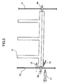
- FIG.5 is a plan view of the double-side operation unit shown in FIG.4A and FIG.4B.
- FIG.6A is a sectional view illustrating the operation of the rear end guide 9 upon drawing out the double-side operation unit.
- FIG.6B is a sectional view illustrating the operation of the rear end guide 9 upon setting the double-side operation unit.
- a turning angle ⁇ of the rear end guide 9 in the direction indicated by the arrow C is set by a stopper 16.
- the positioning member 11 and the elastic member 14 contact each other at a point D.
- the rear end guide 9 turns so that the projection 9b contacts the stopper 16 at a point E so as to position the rear end guide 9.
- the elastic member 14 elastically shrinks by ( ⁇ 1- ⁇ 2) so as to enable a sure contact of the projection 9b and the stopper 16 at the point E.
- the elastic shrinkage of the elastic member 14 compensates variations in dimensional tolerances of the heretofore-mentioned components so as to secure an accuracy of the turning angle ⁇ of the rear end guide 9.
- the turning angle ⁇ of the rear end guide 9 can be made variable by the following arrangement.
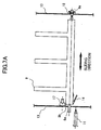
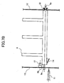
- FIG.7A and FIG.7B are plan views of the double-side operation unit in which the turning angle ⁇ of the rear end guide 9 is variable.
- FIG.7A illustrates a position of the rear end guide 9 upon setting a turning angle ⁇ 1.
- FIG.7B illustrates a position of the rear end guide 9 upon setting a turning angle ⁇ 2.
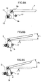
- FIG.8A is a sectional view of the rear end guide 9 upon drawing out the double-side operation unit.
- FIG.8B is a sectional view of the rear end guide 9 upon setting the turning angle ⁇ 1.
- FIG.8C is a sectional view of the rear end guide 9 upon setting the turning angle ⁇ 2.
- the rear end guide 9 can slide in directions indicated by a double-pointed arrow shown in FIG.7A.
- two grooves are formed in the turning axle 9a at an end portion (right in FIG.7A and FIG.7B) opposite to an end where the positioning member 11 contacts the elastic member 14.
- a stepped stopper 17 composed of two steps of cylindrical projections is provided on the side surface of the double-side operation unit 13 in place of the stopper 16.
- the number of the grooves formed in the turning axle 9a and the number of the steps composing the stepped stopper 17 are not limited to two, but may be more than two.
- the rear end guide 9 is arranged at such a position that the projection 9b contacts the larger-diameter cylindrical projection of the stepped stopper 17.
- a positioning of the rear end guide 9 in the sliding directions thereof is performed by inserting a stopping ring 18 into the outer groove formed in the turning axle 9a.
- FIG.9 is an illustration showing details of a part where the stopping ring 18 is mounted.
- An axle bearing 13a formed in the other side surface of the double-side operation unit 13 accepts the outer groove formed in the turning axle 9a passed through and supported on a hole 13b of a supporting board.
- the stopping ring 18 is fit into the axle bearing 13a so as to fix the turning axle 9a.
- a turning of the rear end guide 9 is stopped at a point G such that the turning angle becomes ⁇ 1, as shown in FIG.8B.
- the rear end guide 9 is slid toward right (in the figure) to such a position that the projection 9b contacts the smaller-diameter cylindrical projection of the stepped stopper 17.
- the axle bearing 13a accepts the inner groove formed in the turning axle 9a, and the stopping ring 18 is fit into the axle bearing 13a so as to fix the turning axle 9a.
- a turning of the rear end guide 9 is stopped at a point H such that the turning angle becomes ⁇ 2, as shown in FIG.8C.
- the above-described arrangement enables the turning angle ⁇ of the rear end guide 9 to be varied arbitrarily with ease. Accordingly, the present arrangement can secure a stacking space for a still larger-size sheet, and also can secure an allowance for a curling paper, according to requirements on each occasion. Consequently, the present arrangement increases a general-purpose property of the double-side operation unit 13 per se.
- the following arrangement enables the turning angle ⁇ of the rear end guide 9 to be varied continuously by indefinite steps.
- FIG.10 is a plan view of the double-side operation unit in which the turning angle ⁇ of the rear end guide 9 can be varied continuously by indefinite steps.
- the rear end guide 9 can slide in directions indicated by a double-pointed arrow shown in FIG.10.
- a positioning of the rear end guide 9 in the sliding directions thereof is performed by a dial member 20 mounted on the turning axle 9a at an end (right in FIG.7A and FIG.7B) opposite to an end where the positioning member 11 contacts the elastic member 14.
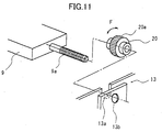
- FIG.11 is an illustration showing details of a part where the dial member 20 is mounted on the turning axle 9a.
- a male screw is formed on the turning axle 9a, and a female screw is formed in a through hole of the dial member 20, so as to together form a screw structure fixing the turning axle 9a borne by the axle bearing 13a.
- an outer peripheral surface 20a of the dial member 20 has a nonskid form such as grooves. Accordingly, the rear end guide 9 can slide continuously by indefinite steps in accordance with revolutions of the dial member 20 in directions indicated by a double-pointed arrow F.
- a conical stopper 19 composed of a conical projection is provided on the side surface of the double-side operation unit 13 in place of the stepped stopper 17.
- a contact point J between the projection 9b of the rear end guide 9 and the conical stopper 19 can be shifted continuously by indefinite steps in accordance with above-described indefinite-step slide of the rear end guide 9. Accordingly, the turning angle ⁇ of the rear end guide 9 can be adjusted finely by indefinite steps. Therefore, this arrangement enables an adjustment of varying angles resulting from variations in dimensional tolerances of the heretofore-mentioned components so as to realize an optimal sheet conveyance.
Landscapes
- Physics & Mathematics (AREA)
- General Physics & Mathematics (AREA)
- Registering Or Overturning Sheets (AREA)
Abstract
Description
Claims (7)
- A double-sided image forming device comprising a double-side operation unit (13) capable of sliding in relation to a body of said double-sided image forming device in a direction perpendicular to a direction of conveying a sheet, the double-side operation unit (13) including:characterized in that:a sheet reversing unit (1, 2, 3) including a switchback conveying path (2) for reversing a front side and a back side of the sheet conveyed from an image forming unit provided in said body, the switchback conveying path (2) having a length (L) smaller than a length (L Pmax) of a conveyable maximum-size sheet; anda reconveying path (5) for reconveying said sheet to said image forming unit so as to form an image on said back side,a rear end guide (9) is provided in said switchback conveying path (2) so as to guide a rear end of a large-size sheet.
- The double-sided image forming device as claimed in claim 1, characterized in that said rear end guide (9) is turned in accordance with a detachment and an insertion of said double-side operation unit (13) from and to said body.
- The double-sided image forming device as claimed in claim 1 or 2, characterized in that said rear end guide (9) is turned by a positioning member (11) provided on said body, while said double-side operation unit (13) is positioned by said positioning member (11).
- The double-sided image forming device as claimed in claim 3, characterized in that said rear end guide (9) contacts said positioning member (11) via an elastic member (14) provided in a projecting portion (9b) formed on said rear end guide (9).
- The double-sided image forming device as claimed in claim 4, characterized in that a turning angle () of said rear end guide (9) is determined by a stopper (16; 17; 19) provided on a side surface of said double-side operation unit (13).
- The double-sided image forming device as claimed in claim 5, characterized in that:said rear end guide (9) is capable of sliding in a direction parallel to a turning axle (9a) thereof, andsaid stopper (17) is provided with a plurality of steps, and a plurality of grooves are formed in said turning axle (9a) so as to determine the turning angle () of said rear end guide (9).
- The double-sided image forming device as claimed in claim 5, characterized in that:said rear end guide (9) is slid in a direction parallel to a turning axle (9a) thereof by a screw structure composed of said turning axle (9a) and a dial member (20), andsaid stopper (19) is formed as a conical projection so as to vary the turning angle () of said rear end guide (9) continuously by indefinite steps.
Applications Claiming Priority (2)
| Application Number | Priority Date | Filing Date | Title |
|---|---|---|---|
| JP2001122170 | 2001-04-20 | ||
| JP2001122170A JP4185256B2 (en) | 2000-12-08 | 2001-04-20 | Double-sided image forming device |
Publications (3)
| Publication Number | Publication Date |
|---|---|
| EP1251411A2 true EP1251411A2 (en) | 2002-10-23 |
| EP1251411A3 EP1251411A3 (en) | 2002-12-11 |
| EP1251411B1 EP1251411B1 (en) | 2009-07-22 |
Family
ID=18971921
Family Applications (1)
| Application Number | Title | Priority Date | Filing Date |
|---|---|---|---|
| EP02008126A Expired - Lifetime EP1251411B1 (en) | 2001-04-20 | 2002-04-11 | Double-sided image forming device having a turnable guide guiding a rear end of a large-size sheet |
Country Status (3)
| Country | Link |
|---|---|
| US (1) | US6711377B2 (en) |
| EP (1) | EP1251411B1 (en) |
| DE (1) | DE60233013D1 (en) |
Families Citing this family (6)
| Publication number | Priority date | Publication date | Assignee | Title |
|---|---|---|---|---|
| JP2005089065A (en) * | 2003-09-17 | 2005-04-07 | Ricoh Co Ltd | Sheet conveying apparatus and image forming apparatus, image reading apparatus, and post-processing apparatus including the same |
| JP4414860B2 (en) * | 2004-10-21 | 2010-02-10 | 株式会社リコー | Paper feed tray, paper feed device, and image forming apparatus |
| US8052141B2 (en) | 2007-05-31 | 2011-11-08 | Ricoh Company, Limited | Recording-medium storage device and image forming apparatus |
| JP5094768B2 (en) * | 2008-06-11 | 2012-12-12 | 京セラドキュメントソリューションズ株式会社 | Recording medium conveying apparatus and image forming apparatus |
| US20110052298A1 (en) * | 2009-09-03 | 2011-03-03 | Gianni Cessel | Apparatus for feeding, taking up and duplexing |
| CN105839563A (en) * | 2016-05-24 | 2016-08-10 | 合肥皆达信息科技有限公司 | One-way vehicle-passing barrier gate |
Family Cites Families (11)
| Publication number | Priority date | Publication date | Assignee | Title |
|---|---|---|---|---|
| JP4065101B2 (en) | 1999-10-25 | 2008-03-19 | 株式会社リコー | Double-sided image recording method and apparatus |
| JP2724153B2 (en) | 1988-03-31 | 1998-03-09 | 株式会社リコー | Intermediate tray integration device for image forming apparatus |
| JPH0768012B2 (en) | 1989-05-16 | 1995-07-26 | シャープ株式会社 | Intermediate tray device for double-sided synthesis |
| US5327206A (en) * | 1991-07-17 | 1994-07-05 | Minolta Camera Kabushiki Kaisha | Image forming apparatus including a sheet refeeding unit |
| JPH08157105A (en) * | 1994-12-05 | 1996-06-18 | Ricoh Co Ltd | Double-sided paper feeder |
| US5737682A (en) | 1995-10-03 | 1998-04-07 | Ricoh Company, Ltd. | Duplex sheet feeding device for an image forming apparatus |
| JPH09251221A (en) * | 1996-01-10 | 1997-09-22 | Mita Ind Co Ltd | Transfer paper cover device of intermediate tray part for image forming device |
| JPH1192041A (en) | 1997-09-18 | 1999-04-06 | Ricoh Co Ltd | Image forming device |
| US6145828A (en) * | 1997-11-28 | 2000-11-14 | Mita Industrial Co., Ltd. | Sheet conveyor single-handed parting engagement mechanism |
| KR19990078056A (en) | 1998-03-23 | 1999-10-25 | 이토가 미찌야 | Sheet guide device with sheet position adjusting mechanism and image forming apparatus using the same device |
| JP2002003088A (en) * | 2000-06-21 | 2002-01-09 | Ricoh Co Ltd | Transfer transport drive |
-
2002
- 2002-04-11 EP EP02008126A patent/EP1251411B1/en not_active Expired - Lifetime
- 2002-04-11 US US10/119,835 patent/US6711377B2/en not_active Expired - Lifetime
- 2002-04-11 DE DE60233013T patent/DE60233013D1/en not_active Expired - Lifetime
Also Published As
| Publication number | Publication date |
|---|---|
| DE60233013D1 (en) | 2009-09-03 |
| EP1251411A3 (en) | 2002-12-11 |
| US6711377B2 (en) | 2004-03-23 |
| US20020154929A1 (en) | 2002-10-24 |
| EP1251411B1 (en) | 2009-07-22 |
Similar Documents
| Publication | Publication Date | Title |
|---|---|---|
| JP3729232B2 (en) | Automatic document feeder | |
| JP2004032152A (en) | Automatic document feeder | |
| US5564686A (en) | Automatic document feeder for an image forming apparatus | |
| US6711377B2 (en) | Double-sided image forming device having a turnable guide guiding a rear end of a large-size sheet | |
| US6678076B1 (en) | Image reading apparatus | |
| US7516958B2 (en) | Auto document feeder | |
| US6402139B1 (en) | Sheet material feeder with guides and lateral position adjusting means | |
| US6332610B1 (en) | Sheet containing apparatus | |
| US5685538A (en) | Sheet registration around turn | |
| JP2002347986A (en) | Sheet supplying device, image reading device and image forming device | |
| JP3699838B2 (en) | Image forming apparatus | |
| US7580165B2 (en) | Paper pressing device | |
| JP4185256B2 (en) | Double-sided image forming device | |
| JP6682217B2 (en) | Image reading apparatus and image forming apparatus | |
| US5923941A (en) | Document transport device | |
| JP2003069790A (en) | Image reading apparatus and image forming apparatus provided with this apparatus | |
| JP2520205Y2 (en) | Sheet transfer device | |
| JP4010497B2 (en) | Image forming apparatus | |
| JPH0614548Y2 (en) | Document reader | |
| US20020181031A1 (en) | Automatic document feeder for an image forming apparatus | |
| JPH11106077A (en) | Sheet separating and conveying apparatus and image forming apparatus having the same | |
| JP2905624B2 (en) | Paper feeder | |
| KR970001902Y1 (en) | Paper supply apparatus | |
| JP2002274662A (en) | Sheet feeding device and image reading device | |
| JPH0614558Y2 (en) | Image reader |
Legal Events
| Date | Code | Title | Description |
|---|---|---|---|
| PUAI | Public reference made under article 153(3) epc to a published international application that has entered the european phase |
Free format text: ORIGINAL CODE: 0009012 |
|
| 17P | Request for examination filed |
Effective date: 20020411 |
|
| AK | Designated contracting states |
Kind code of ref document: A2 Designated state(s): AT BE CH CY DE DK ES FI FR GB GR IE IT LI LU MC NL PT SE TR |
|
| AX | Request for extension of the european patent |
Free format text: AL;LT;LV;MK;RO;SI |
|
| PUAL | Search report despatched |
Free format text: ORIGINAL CODE: 0009013 |
|
| AK | Designated contracting states |
Kind code of ref document: A3 Designated state(s): AT BE CH CY DE DK ES FI FR GB GR IE IT LI LU MC NL PT SE TR |
|
| AX | Request for extension of the european patent |
Free format text: AL;LT;LV;MK;RO;SI |
|
| RTI1 | Title (correction) |
Free format text: DOUBLE-SIDED IMAGE FORMING DEVICE HAVING A TURNTABLE GUIDE GUIDING A REAR END OF A LARGE-SIZE SHEET |
|
| RTI1 | Title (correction) |
Free format text: DOUBLE-SIDED IMAGE FORMING DEVICE HAVING A TURNABLE GUIDE GUIDING A REAR END OF A LARGE-SIZE SHEET |
|
| 17Q | First examination report despatched |
Effective date: 20030610 |
|
| AKX | Designation fees paid |
Designated state(s): DE FR GB |
|
| GRAP | Despatch of communication of intention to grant a patent |
Free format text: ORIGINAL CODE: EPIDOSNIGR1 |
|
| GRAS | Grant fee paid |
Free format text: ORIGINAL CODE: EPIDOSNIGR3 |
|
| GRAA | (expected) grant |
Free format text: ORIGINAL CODE: 0009210 |
|
| AK | Designated contracting states |
Kind code of ref document: B1 Designated state(s): DE FR GB |
|
| REG | Reference to a national code |
Ref country code: GB Ref legal event code: FG4D |
|
| REF | Corresponds to: |
Ref document number: 60233013 Country of ref document: DE Date of ref document: 20090903 Kind code of ref document: P |
|
| PLBE | No opposition filed within time limit |
Free format text: ORIGINAL CODE: 0009261 |
|
| STAA | Information on the status of an ep patent application or granted ep patent |
Free format text: STATUS: NO OPPOSITION FILED WITHIN TIME LIMIT |
|
| 26N | No opposition filed |
Effective date: 20100423 |
|
| REG | Reference to a national code |
Ref country code: FR Ref legal event code: PLFP Year of fee payment: 15 |
|
| REG | Reference to a national code |
Ref country code: FR Ref legal event code: PLFP Year of fee payment: 16 |
|
| PGFP | Annual fee paid to national office [announced via postgrant information from national office to epo] |
Ref country code: DE Payment date: 20170419 Year of fee payment: 16 Ref country code: FR Payment date: 20170419 Year of fee payment: 16 Ref country code: GB Payment date: 20170419 Year of fee payment: 16 |
|
| REG | Reference to a national code |
Ref country code: DE Ref legal event code: R119 Ref document number: 60233013 Country of ref document: DE |
|
| GBPC | Gb: european patent ceased through non-payment of renewal fee |
Effective date: 20180411 |
|
| PG25 | Lapsed in a contracting state [announced via postgrant information from national office to epo] |
Ref country code: DE Free format text: LAPSE BECAUSE OF NON-PAYMENT OF DUE FEES Effective date: 20181101 |
|
| PG25 | Lapsed in a contracting state [announced via postgrant information from national office to epo] |
Ref country code: GB Free format text: LAPSE BECAUSE OF NON-PAYMENT OF DUE FEES Effective date: 20180411 |
|
| PG25 | Lapsed in a contracting state [announced via postgrant information from national office to epo] |
Ref country code: FR Free format text: LAPSE BECAUSE OF NON-PAYMENT OF DUE FEES Effective date: 20180430 |