This invention relates generally to a phase change
developer for liquid electrophotography, and more
particularly to a phase change developer that contains a
crystallizable polymeric binder resin and the phase change
developer reversibly changes from solid phase to liquid
phase at or above 22°C and a method for
electrophotographic imaging using the phase change
developer.
In electrophotography, a photoreceptor in the form of a
plate, sheet, belt, or drum having an electrically
insulating photoconductive element on an electrically
conductive substrate is imaged by first uniformly
electrostatically charging the surface of the
photoconductive element, and then exposing the charged
surface to a pattern of light. The light exposure
selectively dissipates the charge in the illuminated
areas, thereby forming a pattern of charged and uncharged
areas (i.e., an electrostatic latent image). A liquid or
dry developer is then deposited in either the charged or
uncharged areas to create a toned image on the surface of
the photoconductive element. The resulting visible image
can be fixed to the photoreceptor surface or transferred
to a surface of a suitable receiving medium such as sheets
of material, including, for example, paper, transparency,
metal, metal coated substrates, composites and the like.
The imaging process can be repeated many times on the
reusable photoconductive element.
In some electrophotographic imaging systems, the latent
images are formed and developed on top of one another in a
common imaging region of the photoreceptor. The latent
images can also be formed and developed in multiple passes
of the photoreceptor around a continuous transport path
(i.e., a multi-pass system). Alternatively, the latent
images can be formed and developed in a single pass of the
photoreceptor around the continuous transport path. A
single-pass system enables the multi-color images to be
assembled at extremely high speeds relative to the multi-pass
system. At each color development station, color
developers are applied to the photoreceptor belt, for
example, by electrically biased rotating developer rolls.
Image developing methods can be classified into liquid
type developing and dry type developing. The dry type
method uses dry developers and the wet type method uses
liquid developers.
Dry developers are generally prepared by mixing and
dispersing colorant particles and a charge director into a
thermoplastic binder resin, followed by milling or
micropulverization. The resulted developer particle sizes
are generally in the range of about 4 to 10 microns, which
size particles are readily carried by air movement. For
this reason, if the fine powders of a dry developer are
scattered, they pose an environmental problem. However,
dry particles provide excellent ease of handling and
stability for the developer particles.
On the other hand, liquid developers are prepared by
dispersing colorant particles, a charge director, and a
binder in an insulating liquid (i.e., a carrier liquid).
Liquid developer based imaging systems incorporate
features similar to those of dry developer based system.
However, liquid developer particles are significantly
smaller than dry developer particles. Because of their
small particle size, ranging from 3 microns to submicron
size, liquid developers are capable of producing very high
resolution images.
The major problems of liquid developers are the emission
of the liquid carrier from liquid developers to the
environment during the drying and transfer process due to
inefficient solvent recovery system; the need to dispose
the waste liquids; and inconvenience since their handling
is difficult and frequent maintenance is required for
maintaining stable image formation.
It would be desirable to provide a novel phase change
developer which provides the advantages of both the dry
and liquid developers. Preferably, the phase change
developer should be stable, easy to be handled, pose no
environmental problems such as solvent emission and dry
toner spill; and provide high resolution images.
Suitably, the phase change developer may reversibly change
from a solid phase to a liquid phase at its melting point
or crystallization temperature. Suitably, the phase
change developer is a solid in storage and before image
development. Conveniently, during image development, the
phase change developer melts at a temperature above its
melting point to form a liquid developer which then
undergoes a liquid electrophotographic process to produce
toned images.
Some phase change developers for liquid electrophotography
have been mentioned in US patents. US Patent No.
5,229,235 discloses a phase change developer comprising a
colorant and an insulating organic material having a
melting point not lower than 30°C. The organic material
is selected from the group of normal paraffins with 19 to
60 carbons, waxes, and crystalline high molecular
material. The preferred organic materials are paraffins
and waxes.
US Patent No. 5,783,350 claims a phase change developer
comprising a colorant, a thermoplastic resin, and an
insulating carrier. The insulating carrier is selected
from the group of a branched or linear aliphatic
hydrocarbon paraffin or wax, a crystalline polymeric resin
having a low molecular weight and a mixture of the
foregoing. Among these, particularly preferred is a
paraffin consisting primarily of an alkane which has a
definite melting point and has a low viscosity after
fusion.
US Patent No. 5,886,067 claims a liquid developer
comprising a carrier liquid, a charge director, and an
organosol having a (co)polymeric steric stabilizer
covalently bonded to a thermoplastic (co)polymeric core
and the (co)polymeric steric stabilizer comprises a
crystallizing polymeric moiety that independently and
reversibly crystallizes at or above 22°C.
However, even though the above-described phase change
developer is used, satisfactory film formation capacity
and resistance to both aggregation and sedimentation
cannot be attained and there is still much room for
improvement.
The present invention aims to provide a phase change
developer for liquid electrophotography which is resistant
to both aggregation and sedimentation and is capable of
rapid film formation and a method for electrophotographic
imaging using the phase change developer.
According to a first aspect, the present invention
provides a phase change developer comprising: (a) a
carrier having a Kauri-butanol number less than 30; and
(b) an organosol comprising a graft (co)polymeric steric
stabilizer covalently bonded to a thermoplastic
(co)polymeric core, wherein the thermoplastic
(co)polymeric core is insoluble in the carrier, the
(co)polymeric steric stabilizer comprises a crystallizing
polymeric moiety that independently and reversibly
crystallizes at or above 30°C, and the phase change
developer has an activation point at or above 22°C.
Preferably, the phase change developer has a melting
point, exudation temperature, flow temperature or melt
temperature at or above 22°C.
Preferably, the crystallizing polymeric moiety is a
polymeric side-chain covalently bonded to the
(co)polymeric steric stabilizer. Alternatively, the
crystallizing polymeric moiety is a polymeric main-chain
covalently bonded to the (co)polymeric steric stabilizer.
Preferably, the phase change developer further includes at
least one colorant. The colorant may be physically
associated with the thermoplastic (co)polymeric core.
Preferably, the crystallizing polymeric moiety is derived
from a polymerizable monomer selected form the group
consisting of hexacontanyl (meth)acrylate, pentacosanyl
(meth)acrylate, behenyl (meth)acrylate, octadecyl
(meth)acrylate, hexyldecyl acrylate, tetradecyl acrylate,
and amino functional silicones.
Preferably, the phase change developer has an activation
point between about 30°C and 80°C.
Preferably, the phase change developer further includes a
charge director.
According to a second aspect, the present invention
provides a method for electrophotographic imaging
comprising: forming a patterned distribution of charge as
an image, heating a phase change developer according to
the first aspect of the present invention, and allowing
the developer activated by the heating to distribute over
the patterned distribution of charge as a step in
developing the image.
Preferably, the developer is transferred to a receptor
surface. Preferably, heat and/or pressure fixes the
developer to the receptor surface.
The present invention will now be illustrated, by way of
example only, with reference to the following drawings in
which:
The present invention is directed to a phase change
developer that includes: (a) a carrier having a Kauri-butanol
number less than 30; and (b) an organosol
comprising a graft (co)polymeric steric stabilizer
covalently bonded to a thermoplastic (co)polymeric core
that is insoluble in the carrier, the (co)polymeric steric
stabilizer comprising a crystallizing polymeric moiety
(e.g., located on a side-chain or main-chain) that
independently (that is, this moiety may crystallize even
if other moieties in the stabilizer do not crystallize)
and reversibly (that is, the moiety, after
crystallization, can be rendered amorphous by physical
processes) crystallizes at or above 30°C, wherein the
phase change developer has an activation point, such as a
melting point, exudation temperature, flow temperature or
melt temperature at or above 22°C.
The phase change developers will be described primarily
with respect to electrophotographic office printing;
however, it is to be understood that the phase change
developer is not so limited in its utility and may also be
employed in other imaging processes, other printing
processes, or other developer transfer processes, such as
high speed printing presses, photocopying apparatus,
microfilm reproduction devices, facsimile printing, ink
jet printer, instrument recording devices, and the like.
The phase change developer composition comprises a
colorant and a crystalline polymeric binder resin with a
melting point higher than 30°C dispersed in a carrier
having a Kauri-Butanol (KB) number less than 30.
Alternatively, the polarity of adjuvants may be measured
using the Kauri-butanol value for estimation of solvent
power. Here, the crystalline polymeric binder resin
includes a high molecular weight (co)polymeric graft
stabilizer (shell) covalently bonded to an insoluble,
thermoplastic (co)polymeric core.
In the phase change developer composition according to the
present invention, the content of the carrier is
preferably between 5 and 50 parts by weight, based on 100
parts by weight of solid content of organosol. Here, the
organosol may be composed of an insoluble, thermoplastic
(co)polymeric core and a high molecular weight
(co)polymeric graft stabilizer (shell) covalently bonded
thereto. Suitably, if the content of the carrier is less
than 5 parts by weight, the viscosity of the links may be
too high to develop, and may cause many printing defects,
such as low optical density or/and background. If the
content of the carrier is greater than 33 parts by weight,
there may be a need for a carrier remover system in the
printer to remove excess carrier.
The phase change developer composition may further include
a colorant. The content of the colorant is preferably
between 8.3 and 50 parts by weight, based on 100 parts by
weight of solid content of organosol. Suitably, if the
content of the colorant is greater than 50 parts by
weight, the preparation cost of ink composition may
undesirably increase and there may not be enough binder
which may cause the ink film to be weak. If the content
of the colorant is less than 8.3 parts by weight, the
optical density of a final image may be undesirably
reduced.
The phase change developer composition may be resistant to
both aggregation and sedimentation and may be capable of
rapid film formation (rapid self-fixing), which is
particularly useful in electrophotographic, ionographic or
electrostatic imaging and other conventional printing
processes.
"Kauri-Butanol" refers to an ASTM Test Method D1133-54T.
The Kauri-Butanol Number (KB) is a measure of the
tolerance of a standard solution of kauri resin in 1-butanol
to an added hydrocarbon diluent and is measured as
the volume in milliliters (ml) at 25 °C of the solvent
required to produce a certain defined degree of turbidity
when added to 20 g of a standard kauri-1-butanol solution.
Standard values are toluene (KB=105) and 75% by volume of
heptane with 25% by volume toluene (KB=40). Additional
references to Kauri-butanol values include the protocol
described in ASTM Standard: Designation 1133-86. However,
the scope of the aforementioned test method is limited to
hydrocarbon solvents having a boiling point over 40°C. The
method has been modified for application to more volatile
substances such as to 30°C.
The carrier may be selected from a wide variety of
materials that are known in the art, but the carrier
preferably has a Kauri-Butanol number less than 30. The
carrier is typically chemically stable under a variety of
conditions and electrically insulating. Electrically
insulating refers to a material having a low dielectric
constant and a high electrical resistivity. Preferably,
the carrier has a dielectric constant of less than 5, more
preferably less than 3. Electrical resistivities of
carrier are typically greater than 109 Ohm-cm, more
preferably greater than 1010 Ohm-cm, and most preferably
greater than 1010 to 1016 Ohm-cm.
The carrier preferably is also relatively nonviscous in
its liquid state at the operating temperature to allow
movement of the charged particles during development.
Preferably, in addition, the carrier should be chemically
inert with respect to the materials or equipment used in
the liquid electrophotographic process, particularly the
photoreceptor and its release surface.
A number of classes of organic materials meet some or many
of the requirements outlined above. Non-limiting examples
of suitable carrier include aliphatic hydrocarbons or
paraffins (n-pentane, hexane, heptane and the like),
cycloaliphatic hydrocarbons (cyclopentane, cyclohexane and
the like), aromatic hydrocarbons (benzene, toluene, xylene
and the like), halogenated hydrocarbon solvents
(chlorinated alkanes, fluorinated alkanes,
chlorofluorocarbons, and the like), silicone oils and
waxes, vegetable oils and waxes, animal oils and waxes,
petroleum waxes, mineral waxes, synthetic wax, such as
Fischer-Tropsch wax, polyethylene wax, branched paraffinic
waxes and oils, 12-hydroxystearic acid amide, stearic acid
amide, phthalic anhydride imide, and blends of these
materials. Preferred carriers include branched paraffinic
waxes and oils, and blends of these materials.
Suitably, the roles of the crystalline polymeric binder
resin are to be the vehicle for the pigments or dyes, to
provide colloidal stability, and to aid fixing of the
final image. Preferably, the crystalline polymeric binder
resin may contain charging sites or it may be able to
incorporate materials that have charging sites.
Preferably, the crystalline polymeric binder resin has a
melting point above 22°C, more preferably above 30°C, and
most preferably above 40°C. Non-limiting examples of
suitable crystalline polymeric binder resin are polymers
or copolymers derived from side-chain crystallizable and
main-chain crystallizable polymerizable monomers,
oligomers or polymers with melting transitions above 22°C.
Suitable crystalline polymeric binder resins include
homopolymers or copolymers of alkyl acrylates where the
alkyl chain contains more than 13 carbon atoms (e.g.,
tetradecyl acrylate, pentadecyl acrylate, hexadecyl
acrylate, heptadecyl acrylate, octadecyl acrylate, behenyl
acrylate, etc); alkyl methacrylates wherein the alkyl
chain contains more than 17 carbon atoms; ethylene;
propylene; and acrylamide. Other suitable crystalline
polymeric binder resins with melting points above 22°C are
derived from aryl acrylates and methacrylates; high
molecular weight alpha olefins; linear or branched long
chain alkyl vinyl ethers or vinyl esters; long chain alkyl
isocyanates; unsaturated long chain polyesters,
polysiloxanes and polysilanes; amino functional silicone
waxes; polymerizable natural waxes, polymerizable
synthetic waxes, and other similar type materials known to
those skilled in the art.
Suitable crystalline polymeric binder resins can be also
an organosol composed of a high molecular weight
(co)polymeric graft stabilizer (shell) covalently bonded
to an insoluble, thermoplastic (co)polymeric core.
Preferably, the graft stabilizer includes a crystallizable
polymeric moiety that is capable of independently and
reversibly crystallizing at or above 22°C. Suitably, the
graft stabilizer includes a polymerizable organic compound
or mixture of polymerizable organic compounds of which at
least one is a polymerizable crystallizable compound
(PCC). Suitable PCC's include side-chain crystallizable
and main-chain crystallizable polymerizable monomers,
oligomers or polymers with melting transitions above 22°C.
Suitable PCC's include alkylacrylates where the alkyl
chain contains more than 13 carbon atoms (e.g.,
tetradecylacrylate, pentadecylacrylate, hexadecylacrylate,
heptadecylacrylate, octadecylacrylate, etc);
alkylmethacrylates wherein the alkyl chain contains more
than 17 carbon atoms, ethylene; propylene; and acrylamide.
Other suitable PCCs with melting points above 22°C.
include aryl acrylates and methacrylates; high molecular
weight alpha olefins; linear or branched long chain alkyl
vinyl ethers or vinyl esters; long chain alkyl
isocyanates; unsaturated long chain polyesters,
polysiloxanes and polysilanes; amino functional silicone
waxes; polymerizable natural waxes, polymerizable
synthetic waxes, and other similar type materials known to
those skilled in the art.
Preferably, the graft stabilizer has a melting point above
22°C, more preferably above 30°C, and most preferably
above 40°C. Preferably, the graft stabilizer has a
Hildebrand Solubility Parameter closely matching that of
the carrier to ensure that the stabilizer may be
sufficiently solubility in the carrier when the carrier is
in its liquid state. Virtually any polymerizable compound
that exhibits a Hildebrand Solubility Parameter difference
less than 3.0 MPa1/2 relative to the carrier may be used in
forming a crystalline polymeric graft stabilizer provided
that the resulted graft stabilizer has a melting point
above 22°C. In addition, polymerizable compounds that
exhibit a Hildebrand Solubility Parameter difference
greater than 3.0 MPa1/2 relative to the carrier may be used
in forming a copolymeric stabilizer, provided that the
effective Hildebrand Solubility Parameter difference
between the stabilizer and the carrier is less than 3.0
MPa1/2. The absolute difference in Hildebrand Solubility
Parameter between the graft stabilizer and the carrier is
preferably less than 2.6 MPa1/2. The Hildebrand solubility
parameter computes the solubility parameter from molecular
weight, boiling point and density data, which are commonly
available for many materials and which yields values which
are usually within the range of other methods of
calculation:
SP = ( Ev/V)1/2,
where V=molecular weight/density and Ev/V = energy of
vaporization.
Alternatively written, SP = ( Hv/V-RT/V)1/2 where Hv = heat of
vaporization, R = gas constant, and T is the absolute
temperature, °K. For materials, such as high molecular
weight polymers, which have vapor pressures too low to
detect, and thus for which Hv is not available, several
methods have been developed which use the summation of
atomic and group contributions to Hv = i hi, where hi is
the contribution of the ith atom or group to the molar
heat of vaporization. One convenient method has been
proposed by R. F. Fedors, Polymer Engineering and Science,
Vol. 14, p. 147 (1974).
Table 1 lists the Kauri-Butanol Number and Hildebrand
solubility parameter for some common carrier liquids used
in electrophotographic developers and Table 2 lists the
Hildebrand solubility parameter and glass transition
Temperature of common monomers.
| Solvent Values at 25°C |
| Solvent Name | Kauri-Butanol Number by ASTM Method D1133-54T (ml) | Hildebrand Solubility Parameter (MPa1/2) |
| Norpar™ 15 | 18 | 13.99 |
| Norpar™ 13 | 22 | 14.24 |
| Norpar™ 12 | 23 | 14.30 |
| Isopar™ G | 25 | 14.42 |
| Exxsol™ D80 | 28 | 14.60 |
| Source: Calculated from equation No. 31of Polymer Handbook, 3rd Ed., J. Brandrup, E.H. Immergut, Eds. John Wiley, NY, p. VII/522 (1989). |
| Monomer Values at 25°C |
| Monomer Name | Hildebrand Solubility Parameter (MPa1/2) | Glass Transition Temperature (°C) |
| Behenyl Acrylate | 16.74 | / |
| n-Octadecyl Methacrylate | 16.77 | -100 |
| n-Octadecyl Acrylate | 16.82 | -55 |
| Lauryl Methacrylate | 16.84 | -65 |
| Lauryl Acrylate | 16.95 | -30 |
| 2-Ethylhexyl Methacrylate | 16.97 | -10 |
| 2-Ethylhexyl Acrylate | 17.03 | -55 |
| n-Hexyl Methacrylate | 17.13 | -5 |
| n-Butyl Methacrylate | 17.22 | 20 |
| n-Hexyl Acrylate | 17.30 | -60 |
| n-Butyl Acrylate | 17.45 | -55 |
| Ethyl Methacrylate | 17.90 | 66 |
| Ethyl Acrylate | 18.04 | -24 |
| Methyl Methacrylate | 18.17 | 105 |
| Vinyl Acetate | 19.40 | 30 |
| Methyl Acrylate | 20.2 | 5 |
It will be understood by those skilled in the art that
blocking resistance may be observed at temperatures above
22°C, but below the crystallization temperature of the
PCC. Improved blocking resistance may be observed when the
PCC is a major component of the graft stabilizer,
preferably greater than 45% by weight of the graft
stabilizer is the PCC, more preferably greater than or
equal to 75%, most preferably greater than or equal to
90%. Suitable polymerizable organic compounds for use in
the graft stabilizer composition in combination with at
least one PCC include monomers such as, 2-ethylhexyl
acrylate, lauryl acrylate, 2-ethylhexyl (methacrylate),
lauryl methacrylate, hydroxy(ethylmethacrylate), and other
acrylates and methacrylates. Other monomers, macromers or
polymers may be used either alone or in conjunction with
the aforementioned materials, including melamine and
melamine formaldehyde resins, phenol formaldehyde resins,
epoxy resins, polyester resins, styrene and
styrene/acrylic copolymers, acrylic and methacrylic
esters, cellulose acetate and cellulose acetate-butyrate
copolymers, and poly(vinyl butyral) copolymers. Preferred
weight-average molecular weights of the graft stabilizer
are not less than 5,000 Daltons (Da), more preferably not
less than 50,000 Da, most preferably not less than 150,000
Da.
The polydispersity of the graft stabilizer also may have
an effect on imaging and transfer performance of phase
change developers. Generally, it is desirable to maintain
the polydispersity (the ratio of the weight-average
molecular weight to the number average molecular weight)
of the graft stabilizer below 15, more preferably below 5,
most preferably below 2.5.
The graft stabilizer may be chemically bonded to the resin
core (e.g., grafted to the core) or may be adsorbed onto
the core such that it remains as a physically bound
integral part of the resin core. Any number of reactions
known to those skilled in the art may be used to effect
grafting of the soluble polymeric stabilizer to the
organosol core during free radical polymerization. Common
grafting methods include random grafting of polyfunctional
free radicals; ring-opening polymerizations of cyclic
ethers, esters, amides or acetals; epoxidations; reactions
of hydroxyl or amino chain transfer agents with
terminally-unsaturated end groups; esterification
reactions (i.e., glycidyl methacrylate undergoes tertiary-amine
catalyzed esterification with methacrylic acid); and
condensation reactions or polymerization.
One grafting method is that the grafting site is formed by
incorporating hydroxyl groups into the graft stabilizer
during a first free radical polymerization and
catalytically reacting all or a portion of these hydroxyl
groups with an ethylenically unsaturated aliphatic
isocyanate (e.g., meta-isopropenyldimethylbenzyl
isocyanate [TMI] or 2-cyanatoethylmethacrylate [IEM] to
form a polyurethane linkage during a subsequent non-free
radical reaction step. The graft stabilizer is then
covalently bonded to the nascent insoluble acrylic
(co)polymer core via reaction of the unsaturated vinyl
group of the grafting site with ethylenically-unsaturated
core monomers (e.g., vinyl esters, particularly acrylic
and methacrylic esters with carbon numbers less than 7 or
vinyl acetate; vinyl aromatics, such as styrene;
acrylonitrile; n-vinyl pyrrolidone; vinyl chloride and
vinylidene chloride) during a subsequent free radical
polymerization step.
Other methods of effecting grafting of the preformed
polymeric stabilizer to the incipient insoluble core
particle are known to those skilled in the art. For
example, alternative grafting protocols are described in
sections 3.7-3.8 of Barrett Dispersion Polymerization in
Organic Media, K. E. J. Barrett, ed., (John Wiley: New
York, 1975), pp. 79-106. A particularly useful method for
grafting the polymeric stabilizer to core utilizes an
anchoring group. The function of the anchoring groups is
to provide a covalent link between the core part of the
particle and the soluble component of the steric
stabilizer. Suitable monomers containing anchoring groups
include: adducts of alkenylazlactone comonomers with an
unsaturated nucleophile containing hydroxy, amino, or
mercaptan groups, such as 2-hydroxyethylmethacrylate, 3-hydroxypropylmethacrylate,
2-hydroxyethylacrylate,
pentaerythritol triacrylate, 4-hydroxybutyvinylether, 9-octadecen-1-ol,
cinnamyl alcohol, allyl mercaptan,
methallylamine; and azlactones, such as 2-alkenyl-4,4-dialkylazlactone
of the structure

where R
1 = H, or alkyl groups having 1 to 5 carbons,
preferably one carbon, R
2 and R
3 are independently lower
alkyl groups having 1 to 8 carbons, preferably 1 to 4
carbons.
Most preferably, however, the grafting mechanism is
accomplished by grafting an ethylenically-unsaturated
isocyanate (e.g., dimethyl-m-isopropenyl benzylisocyanate,
available from American Cyanamid) to hydroxyl groups
previously incorporated into the graft stabilizer
precursor (e.g., by use of hydroxy ethyl methacrylate).
The core polymer may be made in situ by copolymerization
with the stabilizer monomer. The composition of the
insoluble resin core is preferentially manipulated such
that the resin core exhibits a low glass transition
temperature (Tg) that allows one to formulate a developer
composition containing the resin as a major component to
undergo rapid film formation (rapid self-fixing) in
printing or imaging processes carried out at temperatures
greater than the core Tg, preferably at or above 23°C.
Rapid self-fixing assists in avoiding printing defects
(such as smearing or trailing-edge tailing) and incomplete
transfer in high speed printing. The core Tg of should be
below 23°C, more preferably less than 10°C, most
preferably less than -10°C.
Non-limiting examples of polymerizable organic compounds
suitable for use in the organosol core include
(meth)acrylates such as methyl acrylate, ethyl acrylate,
butyl acrylate, methyl(methacrylate), ethyl(methacrylate),
butyl(methacrylate); (meth)acrylates having aliphatic
amino groups such as N,N-dimethylaminoethyl(meth)acrylate,
N,N-diethylaminoethyl(meth)acrylate,N,N-dibutylaminoethyl(
meth)acrylate, N,N-hydroxyethylaminoethyl(meth)acrylate,
N-benzyl,N-ethylaminoethyl(meth)acrylate,N,N-dibenzylamino
ethyl(meth)acrylate,N-octyl,N,N-dihexylaminoethyl(meth)acr
ylate and the like; nitrogen-containing heterocyclic vinyl
monomers such as N-vinylimidazole, N-vinylindazole,
N-vinyltetrazole, 2-vinylpyridine, 4-vinylpyridine,
2-methyl-5-vinylpyridine,2-vinylquinoline,4-vinylquinolin,
2-vinylpyrazine, 2-vinyloxazole, 2-vinylbenzooxazole and
the like; N-vinyl substituted ring-like amide monomers
such as N-vinylpyrrolidone, N-vinylpiperidone,
N-vinyloxazolidone and the like; (meth)acrylamides such as
N-methylacrylamide,N-octylacrylamide,N-phenylmethacrylamid
e, N-cyclohexylacrylamide, N-phenylethylacrylamide,
N-p-methoxy-phenylacrylamide,acrylamide,
N,N-dimethylacrylamide, N,N-dibutylacrylamide,
N-methyl,N-phenylacrylamide, piperidine acrylate,
morpholine acrylate and the like; aromatic substituted
ethylene monomers containing amino groups such as
dimethlaminostyrene, diethylaminostyrene,
diethylaminomethylstyrene, dioctylaminostyrene and the
like; and nitrogen-containing vinylether monomers such as
vinyl-N-ethyl-N-phenylaminoethylether, vinyl-N-butyl-N-phenylaminoethylether,
triethanolamine divinylether,
vinyldiphenylaminoethylether, vinypyrrolizylaminoether,
vinyl-beta-morpholinoethylether, N-vinylhydroxyethylbenzamide,
m-aminophenylvinylether and
the like, and other acrylates and methacrylates, most
preferred being methylmethacrylate and ethylacrylate.
Other polymers which may be used either alone or in
conjunction with the aforementioned materials, include
melamine and melamine formaldehyde resins, phenol
formaldehyde resins, epoxy resins, polyester resins,
styrene and styrene/acrylic copolymers, vinyl acetate and
vinyl acetate/acrylic copolymers, acrylic and methacrylic
esters, cellulose acetate and cellulose acetate-butyrate
copolymers, and poly(vinyl butyral) copolymers.
Preferably, the optimal weight ratio of the resin core to
the stabilizer shell is on the order of 1/1 to 15/1, more
preferably between 2/1 and 10/1, and most preferably
between 4/1 and 8/1. Undesirable effects may accompany
core/shell ratios selected outside of these ranges. For
example, at high core/shell ratios (above 15), there may
be insufficient graft stabilizer present to sterically-stabilize
the organosol with respect to aggregation. At
low core/shell ratios (below 1), the polymerization may
have insufficient driving force to form a distinct
particulate phase resulting in a copolymer solution, not a
self-stable organosol dispersion. The particle size of the
organosols also influences the imaging, drying and
transfer characteristics of the developers. Preferably,
the primary particle size (determined with dynamic light
scattering) of the organosol is between about 0.05 and 5.0
microns, more preferably between 0.15 and 1 micron, most
preferably between 0.20 and 0.50 microns.
A phase change developer utilizing the aforementioned
organosol may comprise colorant particles embedded in the
thermoplastic organosol resin. The content of the
colorant particles may be between 8.3 and 50 weight parts,
based on 100 weight solid parts of organosol.
Useful colorants are well known in the art and include
materials such as dyes, stains, and pigments. Preferred
colorants are pigments that may be incorporated into the
polymer binder resin, are nominally insoluble in and
nonreactive with the carrier, and are useful and effective
in making visible the latent electrostatic image. Non-limiting
examples of typically suitable colorants include:
phthalocyanine blue (C.I. Pigment Blue 15:1, 15:2, 15:3
and 15:4), monoarylide yellow (C.I. Pigment Yellow 1, 3,
65, 73 and 74), diarylide yellow (C.I. Pigment Yellow 12,
13, 14, 17 and 83), arylamide (Hansa) yellow (C.I. Pigment
Yellow 10, 97, 105, 138 and 111), azo red (C.I. Pigment
Red 3, 17, 22, 23, 38, 48:1, 48:2, 52:1, 81, 81:4 and
179), quinacridone magenta (C.I. Pigment Red 122, 202 and
209) and black pigments such as finely divided carbon
(Cabot Monarch 120, Cabot Regal 300R, Cabot Regal 350R,
Vulcan X72) and the like.
Preferably, the optimal weight ratio of binder resin to
colorant in the developer particles is on the order of 1/1
to 20/1, more preferably between 3/1 and 10/1 and most
preferably between 5/1 and 8/1. The total dispersed
material in the carrier typically represents 0.5 to 70
weight percent, preferably between 5 and 50 weight
percent, most preferably between 10 and 40 weight percent
of the total developer composition.
An electrophotographic phase change developer may be
formulated by incorporating a charge control agent into
the phase change developer. The charge control agent, also
known as a charge director, may provide improved uniform
charge polarity of the developer particles. Suitably, the
content of the charge control agent is within the
generally acceptable range in the art of
electrophotography imaging, typically between 0.17 to 0.83
parts by weight, based on 100 parts by weight of solid
content of organosol. If the content of the charge
control agent exceeds the above range, the excess may give
rise to the disadvantage that the optical density of a
finally obtained image is decreased.
The charge director may be incorporated into the developer
particles using a variety of methods, such as chemically
reacting the charge director with the developer particle,
chemically or physically adsorbing the charge director
onto the developer particle (binder resin or pigment), or
chelating the charge director to a functional group
incorporated into the developer particle. A preferred
method is attachment via a functional group built into the
graft stabilizer. The charge director acts to impart an
electrical charge of selected polarity onto the developer
particles. Any number of charge directors described in the
art may be used. For example, the charge director may be
introduced in the form of metal salts consisting of
polyvalent metal ions and organic anions as the
counterion. Non-limiting examples of suitable metal ions
include Ba(II), Ca(II), Mn(II), Zn(II), Zr(IV), Cu(II),
Al(III), Cr(III), Fe(II), Fe(III), Sb(III), Bi(III),
Co(II), La(III), Pb(II), Mg(II), Mo(III), Ni(II), Ag(I),
Sr(II), Sn(IV), V(V), Y(III), and Ti(IV). Non-limiting
examples of suitable organic anions include carboxylates
or sulfonates derived from aliphatic or aromatic
carboxylic or sulfonic acids, preferably aliphatic fatty
acids such as stearic acid, behenic acid, neodecanoic
acid, diisopropylsalicylic acid, octanoic acid, abietic
acid, naphthenic acid, octanoic acid, lauric acid, tallic
acid, and the like. Preferred positive charge directors
are the metallic carboxylates (soaps) described in U.S.
Pat. No. 3,411,936, incorporated herein by reference,
which include alkaline earth- and heavy-metallic salts of
fatty acids containing at least 6-7 carbons and cyclic
aliphatic acids including naphthenic acid; more preferred
are polyvalent metal soaps of zirconium and aluminum; most
preferred is the zirconium soap of octanoic acid
(Zirconium HEX-CEM from Mooney Chemicals, Cleveland,
Ohio).
The preferred charge direction levels for a given phase
change developer formulation may depend upon a number of
factors, including the composition of the graft stabilizer
and organosol, the molecular weight of the organosol, the
particle size of the organosol, the core/shell ratio of
the graft stabilizer, the pigment used in making the
developer, and the ratio of binder resin to pigment. In
addition, preferred charge direction levels may also
depend upon the nature of the electrophotographic imaging
process, particularly the design of the developing
hardware and photoconductive element. Those skilled in the
art, however, know how to adjust the level of charge
direction based on the listed parameters to achieve the
desired results for their particular application.
Suitably, the useful conductivity range of a phase change
developer is from about 10 to 1200 picomho-cm-1. High
conductivities may generally indicate inefficient
association of the charges on the developer particles and
is seen in the low relationship between current density
and developer deposited during development. Low
conductivities may indicate little or no charging of the
developer particles and lead to very low development
rates. The use of charge director compounds to ensure
sufficient charge associated with each particle is a
common practice. There has, in recent times, been a
realization that even with the use of charge directors
there may be much unwanted charge situated on charged
species in solution in the carrier. Such unwanted charge
may produce inefficiency, instability and inconsistency in
the development.
Any number of methods may be used for effecting particle
size reduction of the pigment in preparation of the phase
change developers. Some suitable methods include high
shear homogenization, ball-milling, attritor milling, high
energy bead(sand) milling, and other means known in the
art. The operating temperature during particle size
reduction is above the melting point of the crystalline
polymeric binder resin. The resulted phase change
developer is either cooled to room temperature to form a
solid which optionally may be turned into a powder by
pulverizing; sprayed to form droplets which then are
cooled to form a powder; transferred to a mold and then
cooled to form a shaped solid; or coated on a substrate
and then cooled to form a coated web with a layer of the
phase change developer.
The phase change developer may be stored and delivered to
a liquid electrophotography imaging system in many
different ways. Non-limiting examples of such developer
storage and delivery system are described below.
The first two examples of developer storage and delivery
system for the phase change developer of this invention
are shown in Figure 1 and Figure 2. The phase change
developer storage and delivery system comprises conductive
substrate 101 in the form of a continuous web or an
endless belt or loop. The phase change developer storage
and delivery system also comprises phase change developer
104 which is placed on top of discrete conductive heating
elements 102. Conductive heating elements 102 may be in
the form of a coating, a stripe, a bar, or any other
useful forms or shapes. Phase change developer 104 may be
in the form of discrete stripes, bars, or coatings placing
on top of conductive heating elements 102, as shown in
Figure 1, or in the form of a continuous coating placing
on top of both conductive heating elements 102 and
conductive substrate 101, as shown in Figure 2. Phase
change developer 104 can be applied on conductive heating
elements 102 by gravure coating, roll coating, curtain
coating, extrusion, lamination, spraying, or other coating
techniques. The coating of phase change developer 102 may
be assisted with ultrasound, electrical field or magnetic
field.
The components described above are all conventional in the
art and any suitable combination of materials for
conductive substrate 101, conductive heating elements 102
and phase change developer 104 may be employed in these
phase change developer storage and delivery systems.
Conductive heating elements 102 are either perpendicular
or skewed at an angle to the edges of substrate 101.
External electrical contact 103 is used to pass a current
through each of conductive heating elements 102.
Therefore, good conductivity between external electrical
contact 103 and discrete conductive heating elements 102
is needed and may be provided by keeping a small portion
of the top surface of each of conductive heating elements
102 free of phase change developer 104. When a current is
passed from electrical contact 103 through each of
conductive heating elements 102 one by one, phase change
developer 104 on each of conductive heating elements 102
is melted and turned into liquid state one by one. These
phase change developer storage and delivery systems may be
run continuously or be indexed.
The term "phase change developer" has an accepted meaning
within the imaging art, however, some additional comments
are useful in view of phenomic differences amongst
mechanisms in this field. As the term indicates, the
developer system is present as one physical phase under
storage conditions (e.g., usually a solid) and transitions
into another phase during development (usually a liquid
phase), usually under the influence of heat or other
directed energy sources. There are basically two
preferred mechanisms in which these phase changes appear:
a) complete conversion of the phase change developer layer
from a solid to a liquid and b) release of a liquid from a
phase change developer layer with a solid carrier in the
phase change developer layer remaining as a solid during
and after development. The first system operates by the
entire layer softening to a point where the entire layer
flows, carrying the active developer component to the
charge distributed areas and depositing the developer
composition on the appropriate areas where the charges
attract the developer. In this case, the developer may be
originally or finally in a solid phase or liquid phase
within the phase change developer layer, but with the
softened (flowable or liquefied) layer carrying the
deveoper or allowing the developer to move over the
surface of the layer having image-effecting charge
distribution over its surface. The second system, where a
liquid developer forms on the surface of the phase change
developer carrying layer, usually maintains a solid
carrying layer with a liquid developer provided on the
surface of the carrier layer. This system may function,
for example, by the developer having a lower softening
point or even being present as a liquid (e.g.,
liquid/solid dispersion, liquid/solid emulsion) in the
solid carrier layer. Upon activation or stimulation (e,g,
by energy, such as heat), the developer composition will
exude or otherwise emit from the surface of the solid
carrier. This can occur by a number of different
phenomena, and the practice of the invention is not
limited to any specifically described phenomenon. For
example, a phase change developer layer may be constructed
by blending a developer composition that is solid at 22°C,
which may be dispersed in a solid binder that is solid at
70°C, and the phase change developer composition coated on
the imaging surface. Upon heating of the phase change
developer layer to a temperature between 25°C and 65°C,
for example, especially where the developer composition is
present at from 1-60% by weight of the phase change
developer layer, the developer will soften or liquefy, and
the developer composition will flow to the surface of the
developer layer. The developer may be present as droplets
and spread by physical action or may flow in sufficient
volume to wet the surface of the developer layer and form
a continuous layer of liquid. Thus, the phase change
developer layer may be heated above room temperature and
below or above the melt, softening or flow temperature of
the carrier solid in the phase change developer layer.
Melting points of the thermoplastic core or the activation
temperature of the phase change developer is preferred to
be between 30 and 90°C, between 35°C and 85°C, between 40
and 80°C, and between 40 and 75 °C.
The concept of an 'activation point' or 'activation
temperature' is particularly easily understood in the
concept of the present invention. At room temperature,
below the activation temperature, the phase change
devloper layer will not allow the developer to readily
distribute over the differentially charged layer to form a
pattern or latent image or image in response to the
distribution of charges. When the activation temperature
has been exceeded on the phase change developer layer, the
developer becomes able to be distributed over the
differentially charged layer to form a pattern or latent
image or image in response to the distribution of charges.
The activation point or activation temperature is
therefore the temperature at which the phase change
developer layer passes from a state in which the developer
is electrophotographically inactive to a state where the
developer is electrophotographically active, as the
temperature increases.
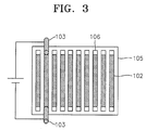
The third example of developer storage and delivery system
for the phase change developer of this invention is shown
in Figure 3. The phase change developer is not shown in
Figure 3. However, it should be placed on top of
conductive heating elements 102. Conductive heating
elements 102 are placed on an electrically insulating
substrate 105. Optionally, conductive contacts 106 are
used to pass current through each of conductive heating
elements 102 one by one by contacting electrical contacts
103. The conductive contacts 106 may be completely
exposed areas or comprise areas over resistive heating
elements that are coated by an essentially solid layer of
phase change developer in which contact regions comprising
a minor amount of the surface area of the phase change
developer layer or a minor or small portion of that layer
over the resistive heating elements as taught in copending
U. S. provisional application Number 60/285,183 and
incorporated by reference herein. The phase change
developer storage and delivery system may be run
continuously or be indexed. When- a current is applied to
conductive heating elements 102, the phase change
developer is melted and turned into liquid state that may
be used subsequently in a liquid electrophotography
process. The components described in Figure 3 are all
conventional in the art and any suitable combination of
materials for insulating substrate 105, conductive heating
elements 102, conductive contacts 106, and the phase
change developer may be employed in the phase change
developer storage and delivery system of the invention.
The fourth example of developer storage and delivery
system for the phase change developer of this invention is
shown in Figure 4. The solid phase change developer of
this invention is molded onto a core to form cylindrical
developer stick 107. The developer stick 107 is mounted
on developer holder 108 so that developer stick 107 comes
in contact with developer roll 109. Developer roll 109 is
rotated at a suitable speed during the development stage
of the electrophotographic process to generate a shear
force causing the outermost surface of developer stick 107
to liquefy. Alternatively, developer roll 109 is heated
to melt only the outermost surface of developer stick 107.
When the phase change developer becomes liquid, a charge
is applied to developer roll 107 causing the toner
particle in the liquid developer to migrate to the surface
of photoreceptor 111. Developer stick 107 rotates at the
same speed as the developer roll 109 in order to maintain
the concentricity of developer stick 107. Developer stick
107 is mounted on developer holder 108 that allows
developer stick 107 to index closer to developer roll 109
as the outer surface of developer stick 107 is used in the
printing process through the use of springs, groves or
other means.
The fifth example of developer storage and delivery system
for the phase change developer of this invention is shown
in Figure 5. This concept of a developer storage and
delivery system comprises solid phase change developer 118
in develop unit 113. Solid phase change developer 118 is
urged toward heating element 115 with openings or
perforations by indexing unit 114. Solid phase change
developer 118 is melted by heating element 115 to form
liquid developer 119 near and in the openings or
perforations of heating element 115. Liquid developer
119 is urged toward developer roll 116 through the
openings or perforations. Develop unit 113 may be
insulated. Heating element 115 may be made of any
material that is resistant to heat and carrier liquids
such as hydrocarbons. Non-limiting examples of materials
for heating element 115 are metals and ceramics. Solid
phase change developer 118 below heating element 115 would
remain in a solid form until it comes in contact with
heating element 115. Heating element 115 would heat a
thin layer of developer at the top to an appropriate
temperature that would allow the toner particles to have
the correct mobility and conductivity to be useful in a
printing mode. As liquid developer 119 is used in the
printing process, the solid ink would be indexed up by
indexing unit 114 to allow the printing apparatus to have
a constant source of developer. This indexing could be
done by using spring loading and tension; a print or dot
counting device that manual indexes solid phase change
developer 118 up according to use; or a device that uses
weight as an indication of the need to index.
In electrophotography, the electrostatic image is
typically formed on a sheet, drum or belt coated with a
photoconductive element by (1) uniformly charging the
photoconductive element with an applied voltage, (2)
exposing and discharging portions of the photoconductive
element with a radiation source to form a latent image,
(3) applying a developer to the latent image to form a
toned image, and (4) transferring the toned image through
one or more steps to a final receptor sheet. In some
applications, it may be desirable to fix the toned image
using a heated pressure roller or other fixing methods
known in the art.
A preferred method and structure for use of phase change
developers is described in copending U. S. provisional
application Number 60/285,183 and titled "DEVELOPER
STORAGE AND DELIVERY SYSTEM FOR LIQUID
ELECTROPHOTOGRAPHY," which application is incorporated
herein by reference for its teachings of phase change
developer systems, compositions and structures.
Suitably, the electrostatic charge of the developer
particles may be either positive or negative. If
electrophotography is carried out by dissipating charge on
a positively (or negatively) charged photoconductive
element, a positively (or negatively) charged developer is
then applied to the regions in which the positive (or
negative) charge was dissipated to develop a toned image.
This image development may be accomplished by using a
uniform electric field produced by a development electrode
spaced near the photoconductive element surface. The phase
change developer is heated to a temperature above its
melting point. A bias voltage is applied to the electrode
intermediate to the initially charged surface voltage and
the exposed surface voltage level. The voltage is adjusted
to obtain the required maximum density level and tone
reproduction scale for halftone dots without any
background deposited. The molten phase change developer is
then caused to flow between the electrode and the
photoconductive element. The charged developer particles
are mobile in the field and are attracted to the
discharged areas on the photoconductive element while
being repelled from the non-discharged, non-image areas.
Excess molten developer remaining on the photoconductive
element is removed by techniques well known in the art.
Thereafter, the photoconductive element surface may be
force dried or allowed to dry at ambient conditions.
The substrate for receiving the image from the
photoconductive element can be any commonly used receptor
material, such as paper, coated paper, polymeric films and
primed or coated polymeric films. Specially coated or
treated metal or metallized surfaces may also be used as
receptors. Polymeric films include plasticized and
compounded polyvinyl chloride (PVC), acrylics,
polyurethanes, polyethylene/acrylic acid copolymer, and
polyvinyl butyrals. Commercially available composite
materials such as those having the trade designations
Scotchcal™, Scotchlite™, and Panaflex™ film materials are
also suitable for preparing substrates.
The transfer of the formed image from the charged surface
to the final receptor or transfer medium may be enhanced
by the incorporation of a release-promoting material
within the dispersed particles used to form the image. The
incorporation of a silicone-containing material or a
fluorine-containing material in the outer (shell) layer of
the particle facilitates the efficient transfer of the
image.
In multicolor imaging, the developers may be applied to
the surface of the dielectric element or photoconductive
element in any order, but for colorimetric reasons,
bearing in mind the inversion that occurs on transfer, it
is sometimes preferred to apply the images in a specified
order depending upon the transparency and intensity of the
colors. A preferred order for a direct imaging or a double
transfer process is yellow, magenta, cyan and black; for a
single transfer process, the preferred order is black,
cyan, magenta and yellow. Yellow is generally imaged first
on the photoreceptor to avoid contamination from other
developers and to be the topmost color layer when
transferred. Black is generally imaged last on the
photoreceptor due to the black developer acting as a
filter of the radiation source and to be the bottom-most
layer after transfer.
Overcoating of the transferred image may optionally be
carried out to protect the image from physical damage
and/or actinic damage. Compositions for overcoatings are
well known in the art and typically comprise a clear film-forming
polymer dissolved or suspended in a volatile
solvent. An ultraviolet light absorbing agent may
optionally be added to the coating composition. Lamination
of protective layers to the image-beating surface is also
well known in the art and may be used with this invention.
These and other aspects of the present invention are
demonstrated in the illustrative examples that follow.
These examples are to be viewed as illustrative of
specific materials falling within the broader disclosure
presented above and are not to be viewed as limiting the
broader disclosure.
EXAMPLES
Glossary of Chemical Abbreviations & Chemical Sources
The following raw materials were used to prepare the
polymers in the examples which follow:
The catalysts used in the examples are
Azobisisobutyronitrile (designated as AIBN, commercially
obtained as VAZO™-64 from DuPont Chemicals, Wilmington,
DE); Dibutyl Tin Dilaurate (designated as DBTDL,
commercially obtained from Aldrich Chemical Co.,
Milwaukee, WI); and 2,2'-Azobisisobutyronitrile
(designated as AZDN, commercially obtained from Elf
Atochem, Philadelphia, PA). The monomers are all
available from Scientific Polymer Products, Inc., Ontario,
NY unless designated otherwise.
The monomers used in the examples are designated by the
following abbreviations: Dimethyl-m-isopropenyl
benzylisocyanate (TMI, commercially obtained from CYTEC
Industries, West Paterson, NJ); Ethyl Acrylate (EA); 2-Hydroxyethyl
Methacrylate (HEMA); lauryl methacrylate
(LMA); methyl methacrylate (MMA); octadecyl methacrylate
(ODA); and behenyl acrylate (BHA).
TEST METHODS
The following test methods were used to characterize the
polymers and developers in the examples that follow:
A. Graft Stabilizer Molecular Weight.
Various properties of the graft stabilizer have been
determined to be important to the performance of the
stabilizer, including molecular weight and molecular
weight polydispersity. Graft stabilizer molecular weight
is normally expressed in terms of the weight average
molecular weight (Mw), while molecular weight
polydispersity is given by the ratio of the weight average
molecular weight to the number average molecular weight
(Mw/Mn). Molecular weight parameters were determined for
graft stabilizers with gel permeation chromatography (GPC)
using tetrahydrofuran as the carrier solvent. Absolute Mw
was determined using a Dawn DSP-F light scattering
detector (commercially obtained from Wyatt Technology
Corp, Santa Barbara, CA), while polydispersity was
evaluated by ratioing the measured Mw to a value of Mn
determined with an Optilab 903 differential refractometer
detector (commercially obtained from Wyatt Technology
Corp, Santa Barbara, CA).
B. Graft Stabilizer And Phase Change Developer Melting
Point
The melting points of graft stabilizers were collected
using a TA Instruments Model 2929 Differential Scanning
Calorimeter (New Castle, DE) equipped with a DSC
refrigerated cooling system (-70°C minimum temperature
limit), and dry helium and nitrogen exchange gases. The
calorimeter ran on a Thermal Analyst 2100 workstation with
version 8.10B software. An empty aluminum pall was used as
the reference. The scanning rate was 10.0°C/min. The
temperature range was from -70°C to 200°C.
C. Percent Solids of Graft Stabilizer, Organosol, and
Developer
Percent solids of the graft stabilizer solutions, and the
organosol and ink dispersions, were determined
gravimetrically using a halogen lamp drying oven
attachment to a precision analytical balance (commercially
obtained from Mettler Instruments Inc., Hightstown, NJ).
Approximately two grams of sample were used in each
determination of percent solids using this sample dry down
method.
D. Preparation of Graft Stabilizers
Comparative Example A
To a 5000 ml 3-neck round flask equipped with a condenser,
a thermocouple connected to a digital temperature
controller, a nitrogen inlet tube connected to a source of
dry nitrogen and a magnetic stirrer, was charged with a
mixture of 2561 g of Norpar™ 12, 848 g of LMA, 27.3 g of
96% HEMA and 8.75 g of AIBN. While the mixture was
magnetically stirred, the reaction flask was purged with
dry nitrogen for 30 minutes at flow rate of approximately
2 liters/minute. A hollow glass stopper was then inserted
into the open end of the condenser and the nitrogen flow
rate was reduced to approximately 0.5 liters/min. The
mixture was heated to 70°C for 16 hours. The conversion
was quantitative.
The mixture was heated to 90°C and held at that
temperature for 1 hour to destroy any residual AIBN, then
was cooled back to 70°C. The nitrogen inlet tube was then
removed, and 13.6 g of 95% DBTDL were added to the
mixture, followed by 41.1 g of TMI. TMI was added drop
wise over the course of approximately 5 minutes while the
mixture was magnetically stirred. The nitrogen inlet tube
was reinserted, the hollow glass stopper in the condenser
was removed, and the reaction flask was purged with dry
nitrogen for 30 minutes at a flow rate of approximately 2
liters/minute. The hollow glass stopper was reinserted
into the open end of the condenser and the nitrogen flow
rate was reduced to approximately 0.5 liters/min. The
mixture was allowed to react at 70°C for 6 hours, at which
time the conversion was quantitative.
The mixture was then cooled to room temperature to form a
graft stabilizer. The graft stabilizer was a viscous,
transparent liquid containing no visible insoluble matter.
The percent solid of the graft stabilizer was determined
to be 26.4%. The graft stabilizer had a Mw of 197,750 Da
and a Mw/Mn of 1.84, based on two independent
measurements. The graft stabilizer was a copolymer of LMA
and HEMA containing random side chains of TMI suitable for
making an organosol. The graft stabilizer is designed
herein as LMA/HEMA-TMI (97/3-4.7% w/w).
Example 1
A 0.72 liter (32 ounce) narrow-mouthed glass bottle was
charged with 483 g of Norpar™ 12, 160 of ODA (Ciba
Specialty Chemicals, USA), 5.1 g of 98% HEMA and 1.57 g of
AZDN. The bottle was purged for 1 minute with dry nitrogen
at a rate of approximately 1.5 liters/min, then sealed
with a screw cap fitted with a Teflon liner. The cap was
secured in place using an electrical tape. The sealed
bottle was then inserted into a metal cage assembly and
installed on the agitator assembly of an Atlas Launder-Ometer
(Atlas Electric Devices Company, Chicago, IL). The
Launder-Ometer was operated at its fixed agitation speed
of 42 rpm with a water bath temperature of 70°C. The
mixture was allowed to react for approximately 16-18 hours
at which time the conversion of monomer to polymer was
quantitative. The mixture was heated to 90°C for 1 hour to
destroy any residual AZDN, then was cooled to room
temperature.
The bottle was then opened and 2.6 g of 95% DBTDL and 7.8
g of TMI were added to the mixture. The bottle was purged
for 1 minute with dry nitrogen at a rate of approximately
1.5 liters/min, then sealed with a screw cap fitted with
Teflon liner. The cap was secured with a screw using
electrical tape. The sealed bottle was then inserted into
a metal cage assembly and installed on the agitator
assembly of the Atlas Launder-Ometer. The Launder-Ometer
was operated at its fixed agitation speed of 42 rpm with a
water bath temperature of 70°C. The mixture was allowed to
react for approximately 4-6 hours, at which time the
conversion was quantitative. The mixture was then cooled
to room temperature to form a graft stabilizer. The graft
stabilizer was a white paste.
The percent of solids of the graft stabilizer was 25.78%.
The graft stabilizer had a Mw of 184.651 and a Mw/Mn of
2.26. The graft stabilizer was a copolymer of ODA and HEMA
containing random side chains of TMI. The graft
stabilizer is designed herein as ODA/HEMA-TMI (97/3-4.7
w/w%).
Example 2
A 0.72 liter (32 ounce) narrow-mouthed glass bottle was
charged with 483 g of Norpar™ 12, 160 g of BHA (Ciba
Specialty Chemicals, USA), 5.1 g of 98% HEMA, and 1.57 g
of AZDN. The bottle was purged for 1 minute with dry
nitrogen at a rate of approximately 1.5 liters/min, then
sealed with a screw cap fitted with a Teflon liner. The
cap was secured in place using an electrical tape. The
sealed bottle was then inserted into a metal cage assembly
and installed on the agitator assembly of an Atlas
Launder-Ometer (Atlas Electric Devices Company, Chicago,
IL). The Launder-Ometer was operated at its fixed
agitation speed of 42 rpm with a water bath temperature of
70°C. The mixture was allowed to react for approximately
16-18 hours at which time the conversion of monomer to
polymer was quantitative. The mixture was heated to 90°C
for 1 hour to destroy any residual AZDN, then was cooled
to room temperature.
The bottle was then opened and 2.6 g of 95% DBTDL and 7.8
g of TMI were added to the mixture. The bottle was purged
for 1 minute with dry nitrogen at a rate of approximately
1.5 liters/min, then sealed with a screw cap fitted with
Teflon liner. The cap was secured with a screw using an
electrical tape. The sealed bottle was then inserted into
a metal cage assembly and installed on the agitator
assembly of the Atlas Launder-Ometer. The Launder-Ometer
was operated at its fixed agitation speed of 42 rpm with a
water bath temperature of 70°C. The mixture was allowed to
react for approximately 4-6 hours, at which time the
conversion was quantitative. The mixture was then cooled
to room temperature to form a graft stabilizer. The graft
stabilizer was a white solid.
The percent of solids of graft stabilizer was 25.74%. The
graft stabilizer had a Mw of 165,900 and a Mw/Mn of 3.89.
The product was a copolymer of BHA and HEMA containing
random side chains of TMI. The graft stabilizer is
designed herein as BHA/HEMA-TMI (97/3-4.7 w/w%).
| Graft Stabilizers |
| Example | Graft Stabilizer (% w/w) | Molecular Weight | Tm (°C) |
| | | Mw | Mw/Mn |
| Comparative Example A | LMA/HEMA-TMI (97/3-4.7) | 197,750 | 1.84 | -22 (Liquid @RT) |
| Example 1 | ODA/HEMA-TMI (97/3-4.7) | 184,651 | 2.26 | 45 |
| Example 2 | BHA/HEMA-TMI (97/3-4.7) | 165,900 | 3.89 | 60 |
| Tm (°C) means the melt temperature in degrees Centigrade |
Organosol Comparative Example B was prepared by using
graft stabilizer Comparative Example A. To a 5000 ml 3-neck
round flask equipped with a condenser, a thermocouple
connected to a digital temperature controller, a nitrogen
inlet tube connected to a source of dry nitrogen, and a
magnetic stirrer, was charged with a mixture of 2950 g of
Norpar™ 12, 281 g of EA, 93 g of MMA, 170 g of Comparative
Example A at 26.4% solids, and 6.3 g of AIBN. While the
mixture was magnetically stirred, the reaction flask was
purged with dry nitrogen for 30 minutes at a flow rate of
approximately 2 liters/minute. A hollow glass stopper was
then inserted into the open end of the condenser and the
nitrogen flow rate was reduced to approximately 0.5
liters/min. The mixture was heated to 70°C for 16 hours.
The conversion was quantitative.
Approximately 350g of n-heptane was added to the cooled
mixture, and the resulting mixture was stripped of
residual monomer using a rotary evaporator equipped with a
dry ice/acetone condenser and operating at a temperature
of 90°C and a vacuum of approximately 15 mm Hg. The
stripped mixture was cooled to room temperature, yielding
an opaque white organosol formed a weak gel over the
course of approximately 2 hours.
This gel organosol is designed LMA/HEMA-TMI//MMA/EA (97/3-4.7//25/75
%w/w).
Example 3
A 0.72 liter (32 ounce) narrow-mouthed glass bottle was
charged with 527 g of Norpar™ 12, 15.60 g MMA, 46.80 g of
EA, 60 g of the graft stabilizer mixture from Example 1 at
25.78% solids, and 0.94 AIBN. The bottle was purged for 1
minute with dry nitrogen at a rate of approximately 1.5
liters/min, then sealed with a screw cap fitted with a
Teflon liner. The cap was secured in place using an
electrical tape. The sealed bottle was then inserted into
a metal cage assembly and installed on the agitator
assembly of an Atlas Launder-Ometer (Atlas Electric
Devices Company, Chicago, IL). The Launder-Ometer was
operated at its fixed agitation speed of 42 rpm with a
water bath temperature of 70°C. The mixture was allowed to
react for approximately 16-18 hours at which time the
conversion of monomer to polymer was quantitative. The
mixture then was cooled to room temperature.
Approximately 65 g of n-heptane were added to the cooled
organosol, and the resulting mixture was stripped of
residual monomer using a rotary evaporator equipped with a
dry ice/acetone condenser and operating at a temperature
of 90°C and a vacuum of approximately 15 mm Hg. The
stripped organosol was an opaque solid when cooled to room
temperature.
This organosol is designed ODA/HEMA-TMI//MMA/EA (97/3-4.7//25/75
%w/w).
Example 4
A 0.72 liter (32 ounce) narrow-mouthed glass bottle was
charged with 527g of Norpar™ 12, 15.60 g MMA, 46.80 g of
EA, 60 g of the graft stabilizer mixture from Example 2 at
25.74% solids, and 0.94 AIBN. The bottle was purged for 1
minute with dry nitrogen at a rate of approximately 1.5
liters/min, then sealed with a screw cap fitted with a
Teflon liner. The cap was secured in place using an
electrical tape. The sealed bottle was then inserted into
a metal cage assembly and installed on the agitator
assembly of an Atlas Launder-Ometer (Atlas Electric
Devices Company, Chicago, IL). The Launder-Ometer was
operated at its fixed agitation speed of 42 rpm with a
water bath temperature of 70°C. The mixture was allowed to
react for approximately 16-18 hours at which time the
conversion of monomer to polymer was quantitative. The
mixture then was cooled to room temperature.
Approximately 65 g of n-heptane were added to the cooled
organosol, and the resulting mixture was stripped of
residual monomer using a rotary evaporator equipped with a
dry ice/acetone condenser and operating at a temperature
of 90°C and a vacuum of approximately 15 mm Hg. The
stripped organosol was an opaque solid when cooled to room
temperature.
This organosol is designed BHA/HEMA-TMI//MMA/EA (97/3-4.7//25/75
%w/w).
Example 5
A 0.72 liter (32 ounce) narrow-mouthed glass bottle was
charged with 527 g of Norpar™ 12, 37.44 g of EA, 12.48 g
of MAA, 12.48 g of BHA, 60 g of the graft stabilizer
mixture from Example 2 at 25.74% solids, and 0.94 AIBN.
The bottle was purged for 1 minute with dry nitrogen at a
rate of approximately 1.5 liters/min, then sealed with a
screw cap fitted with a Teflon liner. The cap was secured
in place using an electrical tape. The sealed bottle was
then inserted into a metal cage assembly and installed on
the agitator assembly of an Atlas Launder-Ometer (Atlas
Electric Devices Company, Chicago, IL). The Launder-Ometer
was operated at its fixed agitation speed of 42 rpm with a
water bath temperature of 70°C. The mixture was allowed to
react for approximately 16-18 hours at which time the
conversion of monomer to polymer was quantitative. The
mixture then was cooled to room temperature.
Approximately 65 g of n-heptane were added to the cooled
organosol, and the resulting mixture was stripped of
residual monomer using a rotary evaporator equipped with a
dry ice/acetone condenser and operating at a temperature
of 90°C and a vacuum of approximately 15 mm Hg. The
stripped organosol was an opaque solid when cooled to room
temperature. This organosol is designed BHA/HEMA-TMI//MMA/EA/BHA
(97/3-4.7//20/60/20 %w/w).
Example 6
This example illustrates the use of the silicone wax to
prepare a solid organosol. A 5000 ml 3-neck round flask
equipped with a condenser, a thermocouple connected to a
digital temperature controller, a nitrogen inlet tube
connected to a source of dry nitrogen and a magnetic
stirrer, was charged with a mixture of 1587 g of
Norpar™ 12, 84 g of Silicone Wax GP-628 (Genesee Polymers
Corporation, Flint, MI), 8.4 g of TMI, 224 g of EA, 112 g
of MMA, and 6.3 g of AIBN. While the mixture was
magnetically stirred, the reaction flask was purged with
dry nitrogen for 30 minutes at a flow rate of
approximately 2 liters/minute. A hollow glass stopper was
then inserted into the open end of the condenser and the
nitrogen flow rate was reduced to approximately 0.5
liters/min. The mixture was heated to 70°C for 16 hours.
The conversion was quantitative.
Approximately 350 g of n-heptane was added to the cooled
organosol, and the resulting mixture was stripped of
residual monomer using a rotary evaporator equipped with a
dry ice/acetone condenser and operating at a temperature
of 90°C and a vacuum of approximately 15 mm Hg. The
stripped organosol was cooled to room temperature,
yielding an opaque white solid. This organosol is
designed Silicone Wax-TMI//MMA/EA.
| Organosols |
| Example | Organosol Compositions (% w/w) | Visual Observation |
| Comparative Example B | LMA/HEMA-TMI//MMA/EA (97/3-4.7//25/75) | Liquid |
| Example 3 | ODA/HEMA-TMI//MMA/EA (97/3-4.7//25/75) | Solid (m.p. 48°C) |
| Example 4 | BHA/HEMA-TMI//MMA/EA (97/3-4.7//25/75) | Solid (m.p. 60°C) |
| Example 5 | BHA/HEMA-TMI//BHA/MMA/EA (97/3-4.7//20/20/60) | Solid (m.p. 60°C) |
| Example 6 | Silicone Wax-TMI//MMA/EA | Solid (m.p. 68°C) |
This is a black phase change developer with an
organosol/pigment ratio of 4 using organosol Example 3.
Example 3 (169 g at 17% (w/w) solids in Norpar™ 12) was
combined with additional 119 g of Norpar™ 12, 7.2 g of
Monarch 120 carbon black (Cabot Corp., Billerica, Mass.)
and 4.39g of 6.15% Zirconium HEX-CEM solution (OMG
Chemical Company, Cleveland, Ohio) in an 8 ounce glass
jar. This mixture was then milled in a 0.5 liter vertical
bead mill (Model 6TSG-1/4, Amex Co., Ltd., Tokyo, Japan)
charged with 390 g of 1.3 mm diameter glass beads (Potter
Industries, Inc., Parsippany, NJ). The mill was operated
at 2,000 RPM for 1.5 hours without cooling water
circulating through the cooling jacket of the milling
chamber.
Examples 8-13
Examples 8-13 can be prepared accordingly by the above-mentioned
method for Example 7 by replacing Example 3 and
Norpar™ 12 by Example 4 and the corresponding carrier as
listed in Table 5 below.
| Phase Change Developers |
| Example | Organosol | Carrier |
| 7 | Example 3 | Norpar™ 12 |
| 8 | Example 4 | Norpar™ 12 |
| 9 | Example 4 | Octadecane (C18) (Alfa Aesar/Johnson Matthey) |
| 10 | Example 4 | Eicosane (C22) (Alfa Aesar/Johnson Matthey) |
| 11 | Example 4 | Pentacosane (C25) (Alfa Aesar/Johnson Matthey) |
| 12 | Example 4 | Microcrystalline Wax W-445 (Witco) |
| 13 | Example 4 | Polyolefin Wax Epolene N-11 (Eastman) |
Preferably, the phase change developer for liquid
electrophotography according to the present invention is
resistant to aggregation or sedimentation and is capable
of rapid film formation. A good image quality may be
attained through electrophotographic imaging using the
same.