EP1251368A1 - Color filter and liquid crystal display device - Google Patents
Color filter and liquid crystal display device Download PDFInfo
- Publication number
- EP1251368A1 EP1251368A1 EP00979064A EP00979064A EP1251368A1 EP 1251368 A1 EP1251368 A1 EP 1251368A1 EP 00979064 A EP00979064 A EP 00979064A EP 00979064 A EP00979064 A EP 00979064A EP 1251368 A1 EP1251368 A1 EP 1251368A1
- Authority
- EP
- European Patent Office
- Prior art keywords
- dots
- liquid crystal
- blue
- color filter
- color
- Prior art date
- Legal status (The legal status is an assumption and is not a legal conclusion. Google has not performed a legal analysis and makes no representation as to the accuracy of the status listed.)
- Withdrawn
Links
Images
Classifications
-
- G—PHYSICS
- G02—OPTICS
- G02B—OPTICAL ELEMENTS, SYSTEMS OR APPARATUS
- G02B5/00—Optical elements other than lenses
- G02B5/20—Filters
-
- G—PHYSICS
- G02—OPTICS
- G02B—OPTICAL ELEMENTS, SYSTEMS OR APPARATUS
- G02B5/00—Optical elements other than lenses
- G02B5/20—Filters
- G02B5/201—Filters in the form of arrays
-
- C—CHEMISTRY; METALLURGY
- C09—DYES; PAINTS; POLISHES; NATURAL RESINS; ADHESIVES; COMPOSITIONS NOT OTHERWISE PROVIDED FOR; APPLICATIONS OF MATERIALS NOT OTHERWISE PROVIDED FOR
- C09K—MATERIALS FOR MISCELLANEOUS APPLICATIONS, NOT PROVIDED FOR ELSEWHERE
- C09K2323/00—Functional layers of liquid crystal optical display excluding electroactive liquid crystal layer characterised by chemical composition
-
- G—PHYSICS
- G02—OPTICS
- G02F—OPTICAL DEVICES OR ARRANGEMENTS FOR THE CONTROL OF LIGHT BY MODIFICATION OF THE OPTICAL PROPERTIES OF THE MEDIA OF THE ELEMENTS INVOLVED THEREIN; NON-LINEAR OPTICS; FREQUENCY-CHANGING OF LIGHT; OPTICAL LOGIC ELEMENTS; OPTICAL ANALOGUE/DIGITAL CONVERTERS
- G02F1/00—Devices or arrangements for the control of the intensity, colour, phase, polarisation or direction of light arriving from an independent light source, e.g. switching, gating or modulating; Non-linear optics
- G02F1/01—Devices or arrangements for the control of the intensity, colour, phase, polarisation or direction of light arriving from an independent light source, e.g. switching, gating or modulating; Non-linear optics for the control of the intensity, phase, polarisation or colour
- G02F1/13—Devices or arrangements for the control of the intensity, colour, phase, polarisation or direction of light arriving from an independent light source, e.g. switching, gating or modulating; Non-linear optics for the control of the intensity, phase, polarisation or colour based on liquid crystals, e.g. single liquid crystal display cells
- G02F1/133—Constructional arrangements; Operation of liquid crystal cells; Circuit arrangements
- G02F1/1333—Constructional arrangements; Manufacturing methods
- G02F1/1335—Structural association of cells with optical devices, e.g. polarisers or reflectors
- G02F1/133509—Filters, e.g. light shielding masks
- G02F1/133514—Colour filters
Definitions
- the present invention relates to color filters and liquid crystal display devices using the color filters, and particularly relate to a liquid crystal display device capable of reproducing a wide range of colors.
- Liquid crystal display devices are used for various apparatuses, such as notebook PCs, personal digital assistants, and digital cameras, which take advantage of the light weight, small thickness, reduced power consumption, and the like of the liquid crystal display devices.
- the display properties (luminance, color reproducibility, viewing angle characteristics, and the like) of the liquid crystal display devices have been much improved, and therefore, use of the liquid crystal display devices is spreading to desktop monitors in addition to conventional notebook PCs.
- desktop LCD monitors liquid crystal television sets having a big screen are being developed in these days.
- improving the color reproducibility leads to a reduced transmittance of the color filter. Accordingly, a color filter having a high transmittance is desired.
- liquid crystal display devices for desktop monitors require a color reproducibility of 50 to 65% in NTSC (National Television System Committee) ratio
- liquid crystal television sets require a wider range of color reproducibility of 60 to 75% in NTSC.
- each of the red, green, and blue colors has the same tone as that of conventional CRT television sets.
- the color properties of the conventional CRT television sets are substantially the same as in the EBU (European Broadcasting Union) standards in which the chromaticity coordinates of red, green, and blue in the XYZ colorimetric system are set at (0.640, 0.330), (0.290, 0.600), and (0.150, 0.060), respectively.
- the color temperature of the white color displayed by a conventional CRT television set is set at about 9000 to 10000 K. This temperature is higher than the color temperature of the white color displayed by a liquid crystal display device for desktop monitors, which is set at 6000 to 7500 K.
- the liquid crystal television sets also need a high color temperature of the white color displayed by them.
- Liquid crystal display devices usually, display color images using a backlight source and a color filter in combination.
- a backlight source and a color filter does not lead to a color reproducibility, color tone, and a white color temperature satisfying the requirements for liquid crystal television sets.
- the combination brings about problems in that (1) a small range of colors can be reproduced; (2) color tones in pixels is far away from the EBU standards; (3) the color temperature of the white color displayed thereby is low; and the like.
- the color tone takes on a blue tinge and thus fades.
- the red tone shifts to blue excessively in comparison with when a light source for desktop monitors is used.
- the red chromaticity particularly the x value
- the red chromaticity is reduced to 0.590 to 0.615, and the red chromaticity is far from the EBU standard of (0.640, 0.330), which means the standard television color.
- pigments for the blue dots are selected from blue and violet colors, depending on the application.
- Exemplary pigments for the blue dots include Pigment Blue PB-6, PB-15 (15:1, 15:2, 15:3, 15:4, 15:6), PB-21, PB-22, PB-28, PB-60, and PB-64 and Pigment Violet PV-14, PV-19, PV-23, PV-29, PV-32, PV-33, PV-36, PV-37, PV-38, PV-40, and PV-50.
- some pigments having excellent characteristics are selected from these pigments.
- Blue pigments particularly with a phthalocyanine skeleton have excellent light stability and heat resistance, and therefore, they are suitable for use in color filters.
- the conventional combination of the back light and the color filter does not satisfy all the color characteristics (color reproducibility, color tone, and color temperature of the white color displayed), which are the requirements for liquid crystal display devices capable of reproducing a wide range of colors, and particularly for liquid crystal television sets.
- preparing a color filter having an excellent color reproducibility using a conventional blue paste causes problems such as transmittance shortage and poor alignment of liquid crystal molecules, and therefore a liquid crystal display device capable of providing high-quality images has not yet been achieved.
- An object of the present invention is to provide a color filter having both excellent color reproducibility and high transmittance and contributing to increase of display quality and reduction of power consumption in liquid crystal display devices.
- Another object of the present invention is to provide a liquid crystal display device capable of displaying as colorful images as in CRT television sets.
- the inventors have studied hard, consequently finding the following color filter and liquid crystal display device.
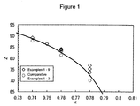
- Fig. 1 is a graph showing changes in chromaticity coordinates (z, Z) of the blue dots in the XYZ colorimetric system, measured with CIE standard light source C, when the mixture ratio of Pigment Blue PB15:6 to Pigment Violet PV23 is changed in accordance with Table 1.
- the chromaticity coordinates of the color filter are measured using glass having the thin layer thereon as a reference in order to eliminate the change in color tones arising from interference by the thin layer.
- the chromaticity coordinates of the color filter are measured using glass as a reference.
- the thin layer must be formed under the same conditions as in the thin layer formed on the color filter.
- the chromaticity coordinates of the color filter of the present invention may be measured by an immersion method using a liquid having substantially the same refractive index as the liquid crystal in order to eliminate the change in color tones arising from interference by the thin layer, such as ITO.
- the color filter of the present invention has at least three color dots, red, green, and blue, and is used in combination with a three-wavelength fluorescent light source.
- the color filter is formed on, but not limited to, a transparent substrate such as glass and a polymer film, and it may be formed on a substrate having switching devices.
- the color filter is patterned in a stripe manner, a delta arrangement, or the like; however, it is not limited to this.
- a fixed columnar spacer may be disposed on the color filter, if necessary.
- the pixels are formed by photolithography, printing, or electrodeposition. Considering pattern formability, it is preferable to use photolithography.
- Exemplary resins forming the pixels include various kinds of resins, such as acrylic resins, alkyd resins, melamine resins, polyvinyl alcohol, phenolic resins, polyamides, polyamide-imides, and polyimides, irrespective of photosensitivity.
- resins soluble in alkaline solution are used because they allow simple equipment for developing or etching processes.
- resins having a carboxyl group are used as an alkali-soluble resin, and specifically an acrylic resin and polyimide are used in view of solvent resistance.
- Polyimide is more preferable because precursors of polyimide serve as a dispersing agent for pigments.
- polyimide is preferable in view of the thermal resistance of the color filter.
- General coloring materials may be used as the pigments in the present invention whether they are organic pigments, inorganic pigments, or dyes.
- the color filter of the present invention includes blue dots whose chromaticity coordinates (z, Z) in the XYZ colorimetric system, measured with the C light source, satisfy the relationships 114 > Z > -1087023z 4 + 3205105z 3 - 3545958z 2 + 1744329z - 321773 and 0.730 ⁇ z ⁇ 0.810.
- the transmittance of the blue dots decreases, and thus they do not exhibit excellent display characteristics.
- the chromaticity coordinates (z, Z) of the blue dots satisfy the relationships 114 > Z > -1087023z 4 + 3205105z 3 - 3545958z 2 + 1744329z - 321773, and 0.730 ⁇ z ⁇ 0.810, and more preferably, 114 > Z > -1361051z 4 + 4044634Z 3 - 4508657z 2 + 2234150z - 415091.5, and 0.735 ⁇ z ⁇ 0.81.
- Z is a parameter representing the transmittance of blue light and is preferably high, but is limited to 114.
- the transmittance of blue light is substantially the same as in the case of using the conventional color filters; hence it does not satisfy the requirements for liquid crystal television sets.
- z is out of the above ranges, excellent color reproducibility is not exhibited.
- the chromaticity coordinates (x, y) of the blue dots satisfy the relationships 0.13 ⁇ x ⁇ 0.15 and 0.08 ⁇ y ⁇ 0.12, preferably, 0.135 ⁇ x ⁇ 0.145 and 0.085 ⁇ y ⁇ 0.115, and more preferably, 0.136 ⁇ x ⁇ 0.142 and 0.085 ⁇ y ⁇ 0.11.
- x and y of the blue dots are out of the ranges described above, a blue color in accordance with the EBU standards, which define standard colors for television sets, cannot be achieved.
- the chromaticity coordinates (x, y) measured with CIE standard light source C satisfy the relationships 0.635 ⁇ x ⁇ 0.665 and 0.31 ⁇ y ⁇ 0.35. More preferably, the chromaticity coordinates satisfy the relationships 0.635 ⁇ x ⁇ 0.665 and 0.32 ⁇ y ⁇ 0.34, yet more preferably, 0.64 ⁇ x ⁇ 0.66 and 0.32 ⁇ y ⁇ 0.34, and yet still more preferably, 0.645 ⁇ x ⁇ 0.66 and 0.32 ⁇ y ⁇ 0.34.
- x of the red dots measured with CIE standard light source C is smaller than 0.635, because the red color is far from the EBU red color standard (0.640, 0.330), which defines standard colors for television sets, and thus excellent color reproducibility cannot be exhibited. Also, it is not preferable that x of the red dots is larger than 0.665, because the transmittance of the dots is reduced and thus the luminance of the liquid crystal display device is reduced.
- the chromaticity coordinates (x, y) of the green dots, measured with CIE standard light source C satisfy the relationships 0.20 ⁇ x ⁇ 0.34 and 0.56 ⁇ y ⁇ 0.65, more preferably, 0.21 ⁇ x ⁇ 0.33 and 0.56 ⁇ y ⁇ 0.64, and still more preferably, 0.215 ⁇ x ⁇ 0.33 and 0.565 ⁇ y ⁇ 0.63. It is not preferable that y of the green dots measured with CIE standard light source C is smaller than 0.56, because the green color is far from the EBU green color standard (0.290, 0.600), which defines standard colors for television sets, and thus excellent color reproducibility cannot be exhibited. Also, it is not preferable that y of the green dots is larger than 0.65, because the transmittance of the dots is reduced and thus the luminance of the liquid crystal display device is reduced.
- all blue, red, and green dots satisfy the above-described ranges so that color characteristics satisfying the requirements for liquid crystal television sets can be achieved.
- At least one selected from various pigments may be used and other pigments may be added as long as the color properties are not degraded.
- Exemplary typical pigments include Pigment Reds PR-2, PR-3, PR-22, PR-38, PR-149, PR-166, PR-168, PR-177, PR-209, PR-224, PR-242, and PR-254; Pigment Oranges PO-5, PO-13, PO-17, PO-31, PO-36, PO-38, PO-40, PO-42, PO-43, PO-51, PO-55, PO-59, PO-61, PO-64, PO-65.
- the present invention is not limited to these and various pigments may be used.
- the above-described pigments may be subjected to surface treatment, such as rosin treatment, acid group treatment, basic treatment, or pigment derivative treatment.
- PB15:6 and PV23 are used for the blue dots of the present invention in view of the color properties, dispersibility, thermal resistance, and the like thereof.
- the weight ratio of PB15:6 to PV23 (PB15:6/PV23) is in the range of 96/4 to 70/30 and the chromaticity coordinate z in the XYZ colorimetric system measured with CIE standard light source C satisfies 0.73 ⁇ z ⁇ 0.81. More preferably, the weight ratio (PB15:6/PV23) is in the range of 92/8 to 75/25 and z satisfies 0.735 ⁇ z ⁇ 0.81. Still more preferably, the weight ratio (PB15:6/PV23) is in the range of 90/10 to 80/20 and z satisfies 0.745 ⁇ z ⁇ 0.81
- a combination of pigments selected from PR177, PR254, PY138, and PY150 is used in view of the color properties, dispersibility, thermal resistance, and the like thereof.
- a combination of PR177 with PR254 is more preferable because it leads to a reduced thickness.
- PR177, PR254, and PY138 are mixed with one another or PR177, PR254, and PY150 are mixed with one another, preferably, the proportions of PR177, PR254, and PY138 or PY150 to the total weight of the pigments are 15 to 50%, 30 to 60%, and 10 to 30%, respectively.
- the proportions of PR177 and PR254 are 3 to 30% and 70 to 97%, respectively. More preferably, the proportions of PR177 and PR254 are 10 to 20% and 80 to 90%, respectively.
- a combination of pigments selected from PG36, PY138, and PY150 is used in view of the color properties, dispersibility, thermal resistance, and the like thereof.
- a combination of PG36 with PY138 is more preferable because it can increase the transmittance.
- the proportions of PG36 and PY138 or PY150 to the total weight of the pigments are 30 to 90% and 10 to 70%, respectively.
- the backlight source of the present invention When the backlight source of the present invention is combined with a conventional color filter to prepare a liquid crystal display device, the entire color takes on a blue tinge and thus the color tone deteriorates. Also, when the color filter of the present invention is combined with a conventional backlight source for desktop monitors, the white color of images takes on a yellow tinge and the white color temperature is reduced; hence the requirements for liquid crystal television sets cannot be satisfied.
- the chromaticity coordinates (x, y) of the backlight source satisfy the expressions 0.265 ⁇ x ⁇ 0.29 and 0.24 ⁇ y ⁇ 0.30, more preferably, 0.27 ⁇ x ⁇ 0.29 and 0.245 ⁇ y ⁇ 0.295, and still more preferably, 0.275 ⁇ x ⁇ 0.285 and 0.25 ⁇ y ⁇ 0.29. More preferably, the characteristics of the color filter and others satisfy the properties described above.
- a color paste containing at least a polyimide precursor, an organic pigment, and a solvent is applied to the surface of a transparent substrate and is then dried by air, heat, or vacuum.
- a colored polyimide precursor film is formed.
- the drying is performed at a temperature in the range of 50 to 180°C for 1 to 3 hours using an oven or a hotplate.
- the resulting colored polyimide precursor film is patterned by regular wet etching.
- a positive photoresist is applied to the surface of the colored polyimide precursor film to form a photoresist layer.
- a mask is disposed above the photoresist layer and is then exposed to ultraviolet light with an exposure apparatus. After exposure, the photoresist layer and the colored polyimide precursor film are simultaneously subjected to etching with an alkaline developer for positive photoresist. After etching, an unnecessary photoresist layer is removed.
- the colored polyimide precursor film is heated to be changed into a colored polyimide film.
- This heat treatment normally, is performed in the air, a nitrogen atmosphere, or vacuum for 0.5 to 5 hours, in succession or in stages, at a temperature of 150 to 450°C, and preferably at a temperature of 180 to 350°C.
- the color filter is provided with, if necessary, a transparent protective layer thereon and a transparent electrode, such as ITO, on the protective layer. Subsequently, a liquid crystal-alignment layer subjected to rubbing, which is performed to align liquid crystal molecules, is disposed on the transparent electrode. Next, this color filter substrate and a transparent electrode substrate which is formed by disposing a transparent electrode, such as ITO film, on a transparent substrate are bonded so as to opposing each other and have spacers for maintaining a cell gap therebetween.
- a transparent electrode such as ITO
- the transparent electrode substrate may have a thin-film transistor (TFT) element, a thin-film diode (TFD) element, a scanning line, a signal line, and the like in addition to the transparent electrode in order to prepare a TFT liquid crystal display device or a TFD liquid crystal display device.
- TFT thin-film transistor
- TFD thin-film diode
- the transmittance and the chromaticity coordinates are measured with a microspectrophotometer "MCPD-2000" produce by Otsuka Electronics Co., Ltd.
- MCPD-2000 microspectrophotometer
- Each chromaticity coordinate is a value measured at 2-degree field of observation.
- the thickness of dots is measured with a surface texture and contour measuring instrument "SURFCOM" 1500A produced by Tokyo Seimitsu Co., Ltd.
- a solution prepared by diluting 20.0 g of the above-described polymer solution (PAA-1) with 30.0 g of ⁇ -butyrolactone was added to 50.0 g of the above-described dispersed solution (BJD-1) to obtain a blue-colored paste (BJP-1).
- a red-colored paste (RJP-1) containing PR254 and PR177, acting as pigments, in a ratio of 90/10, a green-colored paste (GJP-1) containing PG36 and PY138 in a ratio of 55/45, and a black-colored paste containing carbon black were prepared.
- the black-colored paste was applied and dried at 120°C for 20 minutes.
- a positive photoresist (OFPR-800 produced by Tokyo Ohka Kogyo Co., LTD) was applied on the black photoresist and dried at 90°C for 10 minutes.
- PLA-501F produced by Canon Inc.
- the sample was immersed in a developer of 2.25% solution of tetramethylammonium hydroxide so that the photoresist and the black coating film were simultaneously subjected to etching. After etching, an unnecessary photoresist layer was removed with acetone.
- the black coating film was heated at 240°C for 30 minutes so that the polyimide precursor was converted into polyimide.
- the blue-colored paste (BJP-1) was applied to the surface of a glass substrate using a spinner and was then dried at 120°C for 20 minutes.
- the blue coating film was subjected to etching and heat treatment as described above to obtain blue dots.
- the red-colored paste (RJP-1) and the green-colored paste (GJP-1) were applied and subjected to etching and heat treatment to obtain red and green dots.
- An overcoating agent "OPTMER" (SS6917 + SS0917) produced by JSR Corporation was applied on the resulting color filter to a thickness of 1 ⁇ m and was then subjected to sputtering to form an ITO layer with a thickness of 0.14 ⁇ m.
- Color filters were formed as in Examples 1 to 3 except that Pigment Blue PB15:6 and Pigment Violet PV23 were mixed in the ratios shown in Table 1. Using glass having ITO and overcoating film as references, the chromaticity coordinates of the blue dots of the resulting color filter were measured with CIE standard light source C, and the results are shown in Table 1 and Fig. 1. Also, the thicknesses of the dots are shown in Table. 1.
- Example 1 94/6 0.137 0.123 0.740 89.2 1.60
- Example 2 94/6 0.136 0.104 0.760 83.2 2.10
- Example 3 94/6 0.136 0.084 0.780 73.8 3.00
- Example 4 91/9 0.139 0.121 0.740 89.2 1.40
- Example 5 91/9 0.137 0.103 0.760 83.8 1.80
- Example 6 91/9 0.137 0.083 0.780 75.3 2.50
- Example 7 85/15 0.141 0.109 0.750 86.5 1.29
- Example 8 85/15 0.140 0.100 0.760 84.1 1.44
- Example 9 85/15 0.139 0.081 0.780 76.8 1.92
- Color filters were formed as in Example 1 except that the mixture ratio of Pigment Blue PB15:6 to Pigment Violet was changed to 98/2.
- Table. 2 shows the chromaticity coordinates of the resulting color filters measured with CIE standard light source C using glass having ITO and overcoating film as references and the thicknesses of the color filters.
- Comparative Example 2 98/2 0.134 0.106 0.760 81.4 2.58
- Comparative Example 3 98/2 0.135 0.085 0.780 70.0 3.90
- a blue pigment-dispersed solution (BJD-2) of 5% was prepared as in Examples 1 to 3 except than the mixture ratio of Pigment Blue PB15:6 to Pigment Violet PV23 was changed to 88/12.
- a red pigment-dispersed solution (RJD-2) of 5% containing PR254 and PR177 in a ratio of 90/10 and a green pigment-dispersed solution (GJD-2) containing PG36 and PY138 in a ratio of 55/45 were prepared.
- a solution prepared by diluting 5.6 g of the polymer solution (PAA-1) with 38.4 g of ⁇ -butyrolactone was added to 56.0 g of the red pigment-dispersed solution (RJD-2) to obtain a red-colored paste RJP-2.
- a solution prepared by diluting 1.1 g of the polymer solution (PAA-1) with 31.7 g of ⁇ -butyrolactone was added to 67.0 g of the green pigment-dispersed solution (GJD-2) to obtain a green-colored paste GJP-2.
- the chromaticity coordinates (x, y) of red, green, and blue measured with CIE standard light source C were (0.655, 0.335), (0.292, 0.593), and (0.138, 0.092), respectively.
- the chromaticity coordinates (z, Z) of blue were (0.770, 79.4).
- a substrate having TFT elements, pixel electrodes, and the like on a non-alkaline glass was prepared separately to serve as an opposing substrate.
- the opposing substrate and the substrate coated with color pastes (colored layer substrate) were printed with an alignment layer and were subjected to rubbing to align the liquid crystal molecules.
- One of the two substrates was printed with a sealing agent containing micro rods. After inserting a PET film with a thickness of 5 ⁇ m, acting as a spacer, the two substrates were bonded to each other.
- a TN liquid crystal (refractive index anisotropy ⁇ n ⁇ 0.1) capable of being saturated at 4 V was injected and a liquid crystal inlet was sealed with a sealing agent.
- the liquid crystal cell filled with the liquid crystal was disposed between polarizing films with perpendicular polarizing axes to prepare a test liquid crystal cell.
- the liquid crystal cell was provided with an IC driver or the like, and thus, a liquid crystal display device was completed.
- the image was colorful and red, green and blue colors had chromaticity coordinates of (0.642, 0.330), (0.292, 0.598), and (0.148, 0.061), respectively, which are equivalent to the EBU standards.
- the liquid crystal display device having the color filter exhibited a bluish white tone and excellent color balance. The color temperature of the white color displayed thereby was 9800 K and the color properties satisfied the requirements for liquid crystal television sets.
- a backlight source for desktop monitors whose chromaticity coordinates (x, y) in the XYZ colorimetric system were (0.305, 0.295) was placed under the liquid crystal cell prepared in Example 10, and the color tone of the white color displayed thereby were measured.
- the white image took on a yellow tinge and the color balance was unsatisfactory. Also, the color temperature was 7100 K.
- a test liquid crystal cell was prepared as in Example 10 except that the red pigment ratio of PR254 to PY150 was changed to 90/10 and that 100% of PB15:6 was used as a blue pigment.
- the chromaticity coordinates (x, y) of red, green, and blue measured with CIE standard light source C were (0.630, 0.335). (0.298, 0.593), and (0.138, 0.125), respectively.
- the image was not colorful and red, green and blue colors had chromaticity coordinates of (0.612, 0.337), (0.294, 0.605), and (0.147, 0.085), respectively, which are far from the EBU standards.
- the present invention can achieve a color filter capable of realizing both high color reproducibility and a high transmittance, and can thus provide a high-quality liquid crystal display device. Also, by combining the color filter of the present invention with a specific backlight source, images as colorful as in CRT television sets can be displayed.
Landscapes
- Physics & Mathematics (AREA)
- General Physics & Mathematics (AREA)
- Optics & Photonics (AREA)
- Optical Filters (AREA)
- Liquid Crystal (AREA)
Abstract
By preparing a color filter including blue dots whose
chromaticity coordinates (z, Z) in the XYZ colorimetric
system, measured with CIE standard light source C, satisfy
the relational expressions 114 > Z > -1087023z4 + 3205105z3 -
3545958z2 + 1744329z - 321773 and 0.73 ≤ z ≤ 0.81, a color
filter exhibiting an excellent color reproducibility and a
high transmittance can be realized and thus a liquid crystal
display device capable of displaying as colorful images as
in CRT television sets can be achieved.
Description
The present invention relates to color filters and
liquid crystal display devices using the color filters, and
particularly relate to a liquid crystal display device
capable of reproducing a wide range of colors.
Liquid crystal display devices (LCDs) are used for
various apparatuses, such as notebook PCs, personal digital
assistants, and digital cameras, which take advantage of the
light weight, small thickness, reduced power consumption,
and the like of the liquid crystal display devices. The
display properties (luminance, color reproducibility,
viewing angle characteristics, and the like) of the liquid
crystal display devices have been much improved, and
therefore, use of the liquid crystal display devices is
spreading to desktop monitors in addition to conventional
notebook PCs. In addition, by improving the color
reproducibility of desktop LCD monitors, liquid crystal
television sets having a big screen are being developed in
these days. In general, however, improving the color
reproducibility leads to a reduced transmittance of the
color filter. Accordingly, a color filter having a high
transmittance is desired.
While the liquid crystal display devices for desktop
monitors require a color reproducibility of 50 to 65% in
NTSC (National Television System Committee) ratio, liquid
crystal television sets require a wider range of color
reproducibility of 60 to 75% in NTSC. In addition to a
wider range of color reproducibility, it is desired that, in
the liquid crystal television set, each of the red, green,
and blue colors has the same tone as that of conventional
CRT television sets. The color properties of the
conventional CRT television sets are substantially the same
as in the EBU (European Broadcasting Union) standards in
which the chromaticity coordinates of red, green, and blue
in the XYZ colorimetric system are set at (0.640, 0.330),
(0.290, 0.600), and (0.150, 0.060), respectively. Also, the
color temperature of the white color displayed by a
conventional CRT television set is set at about 9000 to
10000 K. This temperature is higher than the color
temperature of the white color displayed by a liquid crystal
display device for desktop monitors, which is set at 6000 to
7500 K. The liquid crystal television sets also need a high
color temperature of the white color displayed by them.
Liquid crystal display devices, usually, display color
images using a backlight source and a color filter in
combination. Such a conventional combination of a backlight
source and a color filter, however, does not lead to a color
reproducibility, color tone, and a white color temperature
satisfying the requirements for liquid crystal television
sets. Specifically, the combination brings about problems
in that (1) a small range of colors can be reproduced; (2)
color tones in pixels is far away from the EBU standards;
(3) the color temperature of the white color displayed
thereby is low; and the like.
On the other hand, when a backlight source having a
high color temperature (about 10000 K) is used for a liquid
crystal display device in combination with the conventional
color filter in order to increase the color temperature of
the white color displayed thereby, the color tone takes on a
blue tinge and thus fades. In particular, the red tone
shifts to blue excessively in comparison with when a light
source for desktop monitors is used. For example, when a
backlight source having a high color temperature is used in
combination with a color filter for desktop monitors, the
red chromaticity, particularly the x value, is reduced to
0.590 to 0.615, and the red chromaticity is far from the EBU
standard of (0.640, 0.330), which means the standard
television color.
In order to prepare a color filter satisfying the EBU
standards using a conventional backlight source for desktop
monitors, it is required to increase the thickness of blue
dots and the concentration of pigments and to improve the
color purity. In this instance, unfortunately, the
transmittance of the blue dots is greatly reduced.
Consequently, the white color takes on a yellow tinge and
thus the display characteristics deteriorate. Also, the
white color temperature is low and thus the requirements for
liquid crystal television sets are not satisfied.
In addition to the reduction of the transmittance,
problems are caused in workability of the color filter and
the shape of the dots. For example, when the thickness of
the dots is increased to improve the color reproducibility
but the concentration of pigments is not changed, the
difference in height between the blue dots and the other
dots is increased. This difference causes poor alignment of
liquid crystal molecules and thus degrades the display
quality. Also, even when the concentration of pigments is
increased and the thickness of dots is reduced to improve
the color reproducibility, workability is degraded and, for
example, the dots are liable to crack.
Considering characteristics, such as transmittance,
contrast, and chromaticity, pigments for the blue dots are
selected from blue and violet colors, depending on the
application. Exemplary pigments for the blue dots include
Pigment Blue PB-6, PB-15 (15:1, 15:2, 15:3, 15:4, 15:6), PB-21,
PB-22, PB-28, PB-60, and PB-64 and Pigment Violet PV-14,
PV-19, PV-23, PV-29, PV-32, PV-33, PV-36, PV-37, PV-38, PV-40,
and PV-50. In practice, some pigments having excellent
characteristics are selected from these pigments. Blue
pigments particularly with a phthalocyanine skeleton have
excellent light stability and heat resistance, and therefore,
they are suitable for use in color filters. When adjustment
of the chromaticity is required, dioxazine violet is added
to a blue pigment having a phthalocyanine skeleton. However,
it is know that the transmittance is reduced in this
instance (Japanese Unexamined Patent Application Publication
Nos. 9-95638 and 9-197663).
As described above, the conventional combination of the
back light and the color filter does not satisfy all the
color characteristics (color reproducibility, color tone,
and color temperature of the white color displayed), which
are the requirements for liquid crystal display devices
capable of reproducing a wide range of colors, and
particularly for liquid crystal television sets.
Also, preparing a color filter having an excellent
color reproducibility using a conventional blue paste causes
problems such as transmittance shortage and poor alignment
of liquid crystal molecules, and therefore a liquid crystal
display device capable of providing high-quality images has
not yet been achieved.
Considering the shortcomings of the conventional art,
the present invention has been devised. An object of the
present invention is to provide a color filter having both
excellent color reproducibility and high transmittance and
contributing to increase of display quality and reduction of
power consumption in liquid crystal display devices.
Another object of the present invention is to provide a
liquid crystal display device capable of displaying as
colorful images as in CRT television sets. In order to
solve the conventional shortcomings, the inventors have
studied hard, consequently finding the following color
filter and liquid crystal display device.
The color temperature T (K) here is derived from the
following equations when the chromaticity coordinates of the
white color displayed by the device in the XYZ colorimetric
system is (Wx, Wy).
n = (Wx - 0.332)/(Wy - 0.1858)
T (K) = -437n3 + 3601n2 - 6861n + 5514.31
Fig. 1 is a graph showing changes in chromaticity
coordinates (z, Z) of the blue dots in the XYZ colorimetric
system, measured with CIE standard light source C, when the
mixture ratio of Pigment Blue PB15:6 to Pigment Violet PV23
is changed in accordance with Table 1.
When a thin layer such as ITO is disposed on a color
filter of the present invention, the chromaticity
coordinates of the color filter are measured using glass
having the thin layer thereon as a reference in order to
eliminate the change in color tones arising from
interference by the thin layer. When a thin layer such as
ITO is not formed on the color filter, the chromaticity
coordinates of the color filter are measured using glass as
a reference. When glass having a thin layer thereon is used
as a reference, the thin layer must be formed under the same
conditions as in the thin layer formed on the color filter.
The chromaticity coordinates of the color filter of the
present invention may be measured by an immersion method
using a liquid having substantially the same refractive
index as the liquid crystal in order to eliminate the change
in color tones arising from interference by the thin layer,
such as ITO.
The color filter of the present invention has at least
three color dots, red, green, and blue, and is used in
combination with a three-wavelength fluorescent light source.
The color filter is formed on, but not limited to, a
transparent substrate such as glass and a polymer film, and
it may be formed on a substrate having switching devices.
The color filter is patterned in a stripe manner, a delta
arrangement, or the like; however, it is not limited to this.
A fixed columnar spacer may be disposed on the color filter,
if necessary.
The pixels are formed by photolithography, printing, or
electrodeposition. Considering pattern formability, it is
preferable to use photolithography. Exemplary resins
forming the pixels include various kinds of resins, such as
acrylic resins, alkyd resins, melamine resins, polyvinyl
alcohol, phenolic resins, polyamides, polyamide-imides, and
polyimides, irrespective of photosensitivity. In particular,
preferably, resins soluble in alkaline solution are used
because they allow simple equipment for developing or
etching processes. Preferably, resins having a carboxyl
group are used as an alkali-soluble resin, and specifically
an acrylic resin and polyimide are used in view of solvent
resistance. Polyimide is more preferable because precursors
of polyimide serve as a dispersing agent for pigments. Also,
polyimide is preferable in view of the thermal resistance of
the color filter.
General coloring materials may be used as the pigments
in the present invention whether they are organic pigments,
inorganic pigments, or dyes.
It is important that the color filter of the present
invention includes blue dots whose chromaticity coordinates
(z, Z) in the XYZ colorimetric system, measured with the C
light source, satisfy the relationships 114 > Z > -1087023z4
+ 3205105z3 - 3545958z2 + 1744329z - 321773 and 0.730 ≤ z ≤
0.810. When the above-described expressions are not
satisfied, the transmittance of the blue dots decreases, and
thus they do not exhibit excellent display characteristics.
Preferably, the chromaticity coordinates (z, Z) of the blue
dots satisfy the relationships 114 > Z > -1087023z4 +
3205105z3 - 3545958z2 + 1744329z - 321773, and 0.730 ≤ z ≤
0.810, and more preferably, 114 > Z > -1361051z4 + 4044634Z3
- 4508657z2 + 2234150z - 415091.5, and 0.735 ≤ z ≤ 0.81.
Z is a parameter representing the transmittance of blue
light and is preferably high, but is limited to 114. In
contrast, when Z is less than the value defined by the
above-described expressions, the transmittance of blue light
is substantially the same as in the case of using the
conventional color filters; hence it does not satisfy the
requirements for liquid crystal television sets. Also, when
z is out of the above ranges, excellent color
reproducibility is not exhibited.
Preferably, the chromaticity coordinates (x, y) of the
blue dots, measured with CIE standard light source C,
satisfy the relationships 0.13 ≤ x ≤ 0.15 and 0.08 ≤ y ≤
0.12, preferably, 0.135 ≤ x ≤ 0.145 and 0.085 ≤ y ≤ 0.115,
and more preferably, 0.136 ≤ x ≤ 0.142 and 0.085 ≤ y ≤ 0.11.
When x and y of the blue dots are out of the ranges
described above, a blue color in accordance with the EBU
standards, which define standard colors for television sets,
cannot be achieved.
In red dots, preferably, the chromaticity coordinates
(x, y) measured with CIE standard light source C satisfy the
relationships 0.635 ≤ x ≤ 0.665 and 0.31 ≤ y ≤ 0.35. More
preferably, the chromaticity coordinates satisfy the
relationships 0.635 ≤ x ≤ 0.665 and 0.32 ≤ y ≤ 0.34, yet
more preferably, 0.64 ≤ x ≤ 0.66 and 0.32 ≤ y ≤ 0.34, and
yet still more preferably, 0.645 ≤ x ≤ 0.66 and 0.32 ≤ y ≤
0.34. It is not preferable that x of the red dots measured
with CIE standard light source C is smaller than 0.635,
because the red color is far from the EBU red color standard
(0.640, 0.330), which defines standard colors for television
sets, and thus excellent color reproducibility cannot be
exhibited. Also, it is not preferable that x of the red
dots is larger than 0.665, because the transmittance of the
dots is reduced and thus the luminance of the liquid crystal
display device is reduced.
Preferably, the chromaticity coordinates (x, y) of the
green dots, measured with CIE standard light source C,
satisfy the relationships 0.20 ≤ x ≤ 0.34 and 0.56 ≤ y ≤
0.65, more preferably, 0.21 ≤ x ≤ 0.33 and 0.56 ≤ y ≤ 0.64,
and still more preferably, 0.215 ≤ x ≤ 0.33 and 0.565 ≤ y ≤
0.63. It is not preferable that y of the green dots
measured with CIE standard light source C is smaller than
0.56, because the green color is far from the EBU green
color standard (0.290, 0.600), which defines standard colors
for television sets, and thus excellent color
reproducibility cannot be exhibited. Also, it is not
preferable that y of the green dots is larger than 0.65,
because the transmittance of the dots is reduced and thus
the luminance of the liquid crystal display device is
reduced.
Preferably, all blue, red, and green dots satisfy the
above-described ranges so that color characteristics
satisfying the requirements for liquid crystal television
sets can be achieved.
In order to obtain dots having the above-described
color properties, at least one selected from various
pigments may be used and other pigments may be added as long
as the color properties are not degraded. Exemplary typical
pigments include Pigment Reds PR-2, PR-3, PR-22, PR-38, PR-149,
PR-166, PR-168, PR-177, PR-209, PR-224, PR-242, and PR-254;
Pigment Oranges PO-5, PO-13, PO-17, PO-31, PO-36, PO-38,
PO-40, PO-42, PO-43, PO-51, PO-55, PO-59, PO-61, PO-64, PO-65.
and PO-71; Pigment Yellows PY-12, PY-13, PY-14, PY-17,
PY-20, PY-24, PY-83, PY-86, PY-93, PY-94, PY-109, PY-110,
PY-117, PY-125, PY-137, PY-138, PY-139, PY-147, PY-148, PY-150,
PY-153, PY-154, PY-166, PY-173, and PY-185; Pigment
Blues PB-15 (15:1, 15:2, 15:3, 15:4, 15:6), PB-21, PB-22,
PB-60, and PB-64; Pigment Violets PV-19, PV-23, PV-29, PV-32,
PV-33, PV-36, PV-37, PV-38, PV-40, and PV-50; and Pigment
Greens 7, 10, 36, and 47. The present invention is not
limited to these and various pigments may be used.
The above-described pigments may be subjected to
surface treatment, such as rosin treatment, acid group
treatment, basic treatment, or pigment derivative treatment.
However, preferably, a combination of PB15:6 and PV23
is used for the blue dots of the present invention in view
of the color properties, dispersibility, thermal resistance,
and the like thereof. In this instance, preferably, the
weight ratio of PB15:6 to PV23 (PB15:6/PV23) is in the range
of 96/4 to 70/30 and the chromaticity coordinate z in the
XYZ colorimetric system measured with CIE standard light
source C satisfies 0.73 ≤ z ≤ 0.81. More preferably, the
weight ratio (PB15:6/PV23) is in the range of 92/8 to 75/25
and z satisfies 0.735 ≤ z ≤ 0.81. Still more preferably,
the weight ratio (PB15:6/PV23) is in the range of 90/10 to
80/20 and z satisfies 0.745 ≤ z ≤ 0.81
The combination of PB15:6 and PV23 has not been
considered useful in practice because it is known that
mixing PB15:6 with PV23 degrades the transmittance. The
inventors, however, found that when the two are mixed with
each other at a specific weight ratio within the above-described
ranges and z of the resulting dots of the color
filter is set in the specific ranges described above, the
dots exhibit a relatively high transmittance, contrary to
the conventional knowledge.
For the red dots of the color filter of the present
invention, preferably, a combination of pigments selected
from PR177, PR254, PY138, and PY150 is used in view of the
color properties, dispersibility, thermal resistance, and
the like thereof. In particular, a combination of PR177
with PR254 is more preferable because it leads to a reduced
thickness.
When PR177, PR254, and PY138 are mixed with one another
or PR177, PR254, and PY150 are mixed with one another,
preferably, the proportions of PR177, PR254, and PY138 or
PY150 to the total weight of the pigments are 15 to 50%, 30
to 60%, and 10 to 30%, respectively.
When PR177 and PR254 are mixed with each other,
preferably, the proportions of PR177 and PR254 are 3 to 30%
and 70 to 97%, respectively. More preferably, the
proportions of PR177 and PR254 are 10 to 20% and 80 to 90%,
respectively.
For the green dots of the color filter of the present
invention, preferably, a combination of pigments selected
from PG36, PY138, and PY150 is used in view of the color
properties, dispersibility, thermal resistance, and the like
thereof. In particular, a combination of PG36 with PY138 is
more preferable because it can increase the transmittance.
When PG36 and PY138 are mixed with each other or PG36
and PY150 are mixed with each other, preferably, the
proportions of PG36 and PY138 or PY150 to the total weight
of the pigments are 30 to 90% and 10 to 70%, respectively.
In the present invention, it is important to combine a
color filter having the blue dots whose chromaticity
coordinates (x, y) in the XYZ colorimetric system satisfy
the expressions 0.13 ≤ x ≤ 0.15 and 0.08 ≤ y ≤ 0.12 and a
backlight source whose chromaticity coordinates (x, y) in
the XYZ colorimetric system satisfy the expressions 0.265 ≤
x s 0.29 and 0.24 ≤ y ≤ 0.30. Thus, excellent color
reproducibility and a white color temperature necessary for
liquid television sets (9000 to 11000 K) were achieved for
the first time. When the backlight source of the present
invention is combined with a conventional color filter to
prepare a liquid crystal display device, the entire color
takes on a blue tinge and thus the color tone deteriorates.
Also, when the color filter of the present invention is
combined with a conventional backlight source for desktop
monitors, the white color of images takes on a yellow tinge
and the white color temperature is reduced; hence the
requirements for liquid crystal television sets cannot be
satisfied. Preferably, the chromaticity coordinates (x, y)
of the backlight source satisfy the expressions 0.265 ≤ x ≤
0.29 and 0.24 ≤ y ≤ 0.30, more preferably, 0.27 ≤ x ≤ 0.29
and 0.245 ≤ y ≤ 0.295, and still more preferably, 0.275 ≤ x
≤ 0.285 and 0.25 ≤ y ≤ 0.29. More preferably, the
characteristics of the color filter and others satisfy the
properties described above.
Next, an exemplary method for manufacturing the color
filter of the present invention will now be described.
A color paste containing at least a polyimide precursor,
an organic pigment, and a solvent is applied to the surface
of a transparent substrate and is then dried by air, heat,
or vacuum. Thus, a colored polyimide precursor film is
formed. In the case of drying by heat, preferably, the
drying is performed at a temperature in the range of 50 to
180°C for 1 to 3 hours using an oven or a hotplate. Next,
the resulting colored polyimide precursor film is patterned
by regular wet etching. First, a positive photoresist is
applied to the surface of the colored polyimide precursor
film to form a photoresist layer. Subsequently, a mask is
disposed above the photoresist layer and is then exposed to
ultraviolet light with an exposure apparatus. After
exposure, the photoresist layer and the colored polyimide
precursor film are simultaneously subjected to etching with
an alkaline developer for positive photoresist. After
etching, an unnecessary photoresist layer is removed.
The colored polyimide precursor film is heated to be
changed into a colored polyimide film. This heat treatment,
normally, is performed in the air, a nitrogen atmosphere, or
vacuum for 0.5 to 5 hours, in succession or in stages, at a
temperature of 150 to 450°C, and preferably at a temperature
of 180 to 350°C.
These steps are performed on pastes of three colors,
red, green, and blue and, if necessary, on a black-colored
paste to complete the color filter for the liquid crystal
display device.
Next, the liquid crystal display device using the color
filter will be described. The color filter is provided with,
if necessary, a transparent protective layer thereon and a
transparent electrode, such as ITO, on the protective layer.
Subsequently, a liquid crystal-alignment layer subjected to
rubbing, which is performed to align liquid crystal
molecules, is disposed on the transparent electrode. Next,
this color filter substrate and a transparent electrode
substrate which is formed by disposing a transparent
electrode, such as ITO film, on a transparent substrate are
bonded so as to opposing each other and have spacers for
maintaining a cell gap therebetween. The transparent
electrode substrate may have a thin-film transistor (TFT)
element, a thin-film diode (TFD) element, a scanning line, a
signal line, and the like in addition to the transparent
electrode in order to prepare a TFT liquid crystal display
device or a TFD liquid crystal display device. Next, liquid
crystal is injected from an inlet provided in a sealing
portion, and then the inlet is sealed. Next, after a
polarizer is bonded to the external surface of the substrate,
an IC driver is mounted, thus completing the liquid display
device.
The transmittance and the chromaticity coordinates are
measured with a microspectrophotometer "MCPD-2000" produce
by Otsuka Electronics Co., Ltd. Each chromaticity
coordinate is a value measured at 2-degree field of
observation.
The thickness of dots is measured with a surface
texture and contour measuring instrument "SURFCOM" 1500A
produced by Tokyo Seimitsu Co., Ltd.
The following is a description according to examples of
the present invention, but the present invention is not
limited to the examples.
Examples 1 to 3
Prepared were 95.1 g of 4,4-diaminodiphenyl ether, 6.2
g of bis(3-aminopropyl)tetramethyldisiloxane, 525 g of γ-butyrolactone,
220 g of N-methyl-2-pyrrolidone, and
subsequently 144.1 g of 3.3',4,4'-biphenyltetracarboxylic
dianhydride was added. Then, the mixture was reacted at
70°C for 3 hours. Then, 3.0 g of phthalic anhydride was
added, followed by a reaction at 70°C for 2 hours to obtain
25 weight percent of polyamic acid solution (PAA-1).
Prepared were 161.3 g of 4,4-diaminobenzanilide, 176.7
g of diaminodiphenyl sulfone, 18.6 g of bis(3-aminopropyl)tetramethyldisiloxane,
2667 g of γ-butyrolactone,
527 g of N-methyl-2-pyrrolidone, and subsequently 439.1 g of
3,3',4,4'-biphenyltetracarboxylic dianhydride was added.
Then, the mixture was reacted at 70°C for 3 hours. Then,
2.2 g of phthalic anhydride was added, followed by a
reaction at 70°C for 2 hours to obtain 20 weight percent
polyamic acid solution (PD-1).
Using 4.23 g (94 wt%) of Pigment Blue PB15:6 and 0.27 g
of Pigment Violet PV23 as pigments, 22.5 g of the above-described
polymer dispersing agent, 42.8g of γ-butyrolactone,
20.2 g of 3-methoxy-3-methyl-1-butanol, and 90 g of glass
beads were blended into the pigments. Using a homogenizer,
the mixture was dispersed at 7000 rpm for 5 hours and then
the glass beads were removed by filtration. Thus, a
dispersed solution of 5% of blue pigment (BJD-1) containing
pigments PB15:6 and PV23 in a weight ratio of 94/6 was
obtained.
A solution prepared by diluting 20.0 g of the above-described
polymer solution (PAA-1) with 30.0 g of γ-butyrolactone
was added to 50.0 g of the above-described
dispersed solution (BJD-1) to obtain a blue-colored paste
(BJP-1).
As in the above, a red-colored paste (RJP-1) containing
PR254 and PR177, acting as pigments, in a ratio of 90/10, a
green-colored paste (GJP-1) containing PG36 and PY138 in a
ratio of 55/45, and a black-colored paste containing carbon
black were prepared.
First, the black-colored paste was applied and dried at
120°C for 20 minutes. Then, a positive photoresist (OFPR-800
produced by Tokyo Ohka Kogyo Co., LTD) was applied on
the black photoresist and dried at 90°C for 10 minutes.
Using an ultraviolet exposure apparatus PLA-501F produced by
Canon Inc., light exposure with an ultraviolet light having
an intensity of 60 mJ/cm3 and a wavelength of 365 nm was
performed through a chrome photomask. After exposure, the
sample was immersed in a developer of 2.25% solution of
tetramethylammonium hydroxide so that the photoresist and
the black coating film were simultaneously subjected to
etching. After etching, an unnecessary photoresist layer
was removed with acetone. The black coating film was heated
at 240°C for 30 minutes so that the polyimide precursor was
converted into polyimide.
Next, the blue-colored paste (BJP-1) was applied to the
surface of a glass substrate using a spinner and was then
dried at 120°C for 20 minutes. The blue coating film was
subjected to etching and heat treatment as described above
to obtain blue dots. In the same way, the red-colored paste
(RJP-1) and the green-colored paste (GJP-1) were applied and
subjected to etching and heat treatment to obtain red and
green dots. An overcoating agent "OPTMER" (SS6917 + SS0917)
produced by JSR Corporation was applied on the resulting
color filter to a thickness of 1 µm and was then subjected
to sputtering to form an ITO layer with a thickness of 0.14
µm.
Using glass having ITO and overcoating film as
references, the chromaticity coordinates of the blue dots of
the resulting color filter were measured with CIE standard
light source C, and the results are shown in Table 1 and Fig.
1. Also, the thicknesses of the dots are shown in Table. 1.
Examples 4 to 9
Color filters were formed as in Examples 1 to 3 except
that Pigment Blue PB15:6 and Pigment Violet PV23 were mixed
in the ratios shown in Table 1. Using glass having ITO and
overcoating film as references, the chromaticity coordinates
of the blue dots of the resulting color filter were measured
with CIE standard light source C, and the results are shown
in Table 1 and Fig. 1. Also, the thicknesses of the dots
are shown in Table. 1.
| Mixture ratio PB15:6/PV23 (wt%) | x | y | Z | Z | Thickness (µm) | |
| Example 1 | 94/6 | 0.137 | 0.123 | 0.740 | 89.2 | 1.60 |
| Example 2 | 94/6 | 0.136 | 0.104 | 0.760 | 83.2 | 2.10 |
| Example 3 | 94/6 | 0.136 | 0.084 | 0.780 | 73.8 | 3.00 |
| Example 4 | 91/9 | 0.139 | 0.121 | 0.740 | 89.2 | 1.40 |
| Example 5 | 91/9 | 0.137 | 0.103 | 0.760 | 83.8 | 1.80 |
| Example 6 | 91/9 | 0.137 | 0.083 | 0.780 | 75.3 | 2.50 |
| Example 7 | 85/15 | 0.141 | 0.109 | 0.750 | 86.5 | 1.29 |
| Example 8 | 85/15 | 0.140 | 0.100 | 0.760 | 84.1 | 1.44 |
| Example 9 | 85/15 | 0.139 | 0.081 | 0.780 | 76.8 | 1.92 |
Color filters were formed as in Example 1 except that
the mixture ratio of Pigment Blue PB15:6 to Pigment Violet
was changed to 98/2. Table. 2 shows the chromaticity
coordinates of the resulting color filters measured with CIE
standard light source C using glass having ITO and
overcoating film as references and the thicknesses of the
color filters.
| Mixture ratio PB15:6/PV23 (wt%) | X | y | z | Z | Thickness (µm) | |
| Comparative Example 1 | 98/2 | 0.135 | 0.125 | 0.740 | 87.8 | 1.90 |
| Comparative Example 2 | 98/2 | 0.134 | 0.106 | 0.760 | 81.4 | 2.58 |
| Comparative Example 3 | 98/2 | 0.135 | 0.085 | 0.780 | 70.0 | 3.90 |
According to the observation of the resulting color
filters with a microscope, a very small amount of cracks was
found in the dots of the color filters of Comparative
Examples 1 to 3, particularly in Comparative Example 3. In
contrast, Examples 1 to 9 did not have any cracks and
exhibited excellent dot-shape characteristics. According to
the comparison of the dot thicknesses at the same z value,
the thicknesses of the dots of Examples 1 to 9 are smaller
than those of Comparative Examples 1 to 3. Also, the liquid
crystal display devices having any color filter of Examples
1 to 9 caused no or little display failure and exhibited
excellent characteristics. In contrast, the liquid crystal
display devices having any color filter of Comparative
Examples 1 to 3 exhibited disclination and, in particular,
the quality of displayed images in Comparative Example 3 was
reduced.
A blue pigment-dispersed solution (BJD-2) of 5% was
prepared as in Examples 1 to 3 except than the mixture ratio
of Pigment Blue PB15:6 to Pigment Violet PV23 was changed to
88/12. As in Examples 1 to 3, a red pigment-dispersed
solution (RJD-2) of 5% containing PR254 and PR177 in a ratio
of 90/10 and a green pigment-dispersed solution (GJD-2)
containing PG36 and PY138 in a ratio of 55/45 were prepared.
A solution prepared by diluting 5.6 g of the polymer
solution (PAA-1) with 38.4 g of γ-butyrolactone was added to
56.0 g of the red pigment-dispersed solution (RJD-2) to
obtain a red-colored paste RJP-2. A solution prepared by
diluting 1.1 g of the polymer solution (PAA-1) with 31.7 g
of γ-butyrolactone was added to 67.0 g of the green pigment-dispersed
solution (GJD-2) to obtain a green-colored paste
GJP-2. A solution prepared by diluting 14.0g of the polymer
solution (PAA-1) with 51.0 g of (γ-butyrolactone was added
to 35.0 g of the blue pigment-dispersed solution (BJD-2) to
obtain a blue-colored paste BJP-2.
Next, a color filter was formed as in Examples 1 to 3.
The chromaticity coordinates (x, y) of red, green, and
blue measured with CIE standard light source C were (0.655,
0.335), (0.292, 0.593), and (0.138, 0.092), respectively.
The chromaticity coordinates (z, Z) of blue were (0.770,
79.4).
A substrate having TFT elements, pixel electrodes, and
the like on a non-alkaline glass was prepared separately to
serve as an opposing substrate. The opposing substrate and
the substrate coated with color pastes (colored layer
substrate) were printed with an alignment layer and were
subjected to rubbing to align the liquid crystal molecules.
One of the two substrates was printed with a sealing agent
containing micro rods. After inserting a PET film with a
thickness of 5 µm, acting as a spacer, the two substrates
were bonded to each other. Next, a TN liquid crystal
(refractive index anisotropy Δn ~0.1) capable of being
saturated at 4 V was injected and a liquid crystal inlet was
sealed with a sealing agent. The liquid crystal cell filled
with the liquid crystal was disposed between polarizing
films with perpendicular polarizing axes to prepare a test
liquid crystal cell. The liquid crystal cell was provided
with an IC driver or the like, and thus, a liquid crystal
display device was completed.
A three-wavelength fluorescent lamp whose chromaticity
coordinates (x, y) in the XYZ colorimetric system were
(0.280, 0.270) was placed under the prepared liquid crystal
cell, and the chromaticity coordinates were measured. The
image was colorful and red, green and blue colors had
chromaticity coordinates of (0.642, 0.330), (0.292, 0.598),
and (0.148, 0.061), respectively, which are equivalent to
the EBU standards. Also, the liquid crystal display device
having the color filter exhibited a bluish white tone and
excellent color balance. The color temperature of the white
color displayed thereby was 9800 K and the color properties
satisfied the requirements for liquid crystal television
sets.
A backlight source for desktop monitors whose
chromaticity coordinates (x, y) in the XYZ colorimetric
system were (0.305, 0.295) was placed under the liquid
crystal cell prepared in Example 10, and the color tone of
the white color displayed thereby were measured. The white
image took on a yellow tinge and the color balance was
unsatisfactory. Also, the color temperature was 7100 K.
A test liquid crystal cell was prepared as in Example
10 except that the red pigment ratio of PR254 to PY150 was
changed to 90/10 and that 100% of PB15:6 was used as a blue
pigment. The chromaticity coordinates (x, y) of red, green,
and blue measured with CIE standard light source C were
(0.630, 0.335). (0.298, 0.593), and (0.138, 0.125),
respectively.
A three-wavelength fluorescent lamp whose chromaticity
coordinates (x, y) in the XYZ colorimetric system were
(0.280, 0.270) was placed under the prepared liquid crystal
cell, and the chromaticity coordinates were measured. The
image was not colorful and red, green and blue colors had
chromaticity coordinates of (0.612, 0.337), (0.294, 0.605),
and (0.147, 0.085), respectively, which are far from the EBU
standards.
As described above, the present invention can achieve a
color filter capable of realizing both high color
reproducibility and a high transmittance, and can thus
provide a high-quality liquid crystal display device. Also,
by combining the color filter of the present invention with
a specific backlight source, images as colorful as in CRT
television sets can be displayed.
Claims (11)
- A color filter comprising blue dots whose chromaticity coordinates (z, Z) in the XYZ colorimetric system, measured with CIE standard light source C, satisfy the relational expressions 114 > Z > -1087023z4 + 3205105z3 - 3545958z2 + 1744329z - 321773 and 0.730 ≤ z ≤ 0.810.
- A color filter comprising blue dots containing Pigment Blue 15:6 (PB15:6) and Pigment Violet 23 (PV23) such that the weight ratio of PB15:6 to PV23 is in the range of 96/4 to 70/30, the blue dots having a chromaticity coordinate z in the XYZ colorimetric system, measured with CIE standard light source C, satisfying 0.73 ≤ z ≤ 0.81.
- A color filter according to Claim 1 or 2, wherein the chromaticity coordinates (x, y) in the XYZ colorimetric system of the blue dots, measured with CIE standard light source C, satisfy the expressions 0.13 ≤ x ≤ 0.15 and 0.08 ≤ y ≤ 0.12.
- A color filter according to Claim 3, further comprising red dots, wherein the chromaticity coordinates (x, y) in the XYZ colorimetric system of the red dots, measured with CIE standard light source C, satisfy the expressions 0.635 ≤ x ≤ 0.665 and 0.31 ≤ y ≤ 0.35.
- A color filter according to Claim 4, further comprising green dots, wherein the chromaticity coordinates (x, y) in the XYZ colorimetric system of the green dots, measured with CIE standard light source C, satisfy the expressions 0.22 ≤ x ≤ 0.34 and 0.56 ≤ y ≤ 0.65.
- A liquid crystal display device comprising: a color filter comprising at least blue dots, red dots, and green dots; and a backlight source, wherein the chromaticity coordinates (x, y) in the XYZ colorimetric system of the blue dots, measured with CIE standard light source C, satisfy the expressions 0.13 ≤ x ≤ 0.15 and 0.08 ≤ y ≤ 0.12, and the chromaticity coordinates (x, y) in the XYZ colorimetric system of the backlight source satisfy the expressions 0.265 ≤ x ≤ 0.29 and 0.24 ≤ y ≤ 0.30.
- A liquid crystal display device according to Claim 6, wherein the chromaticity coordinates (x, y) in the XYZ colorimetric system of the red dots, measured with CIE standard light source C, satisfy the expressions 0.635 ≤ x ≤ 0.665 and 0.31 ≤ y ≤ 0.35.
- A liquid crystal display device according to Claim 7, wherein the chromaticity coordinates (x, y) in the XYZ colorimetric system of the green dots, measured with CIE standard light source C, satisfy the expressions 0.22 ≤ x ≤ 0.34 and 0.56 ≤ y ≤ 0.65.
- A liquid crystal display device according to Claim 6, wherein the chromaticity coordinates (z, Z) in the XYZ colorimetric system of the blue dots, measured with CIE standard light source C, satisfy the expressions 114 > Z > - 1087023z4 + 3205105z3- 3545958z2 + 1744329z - 321773 and 0.73 ≤ z ≤ 0.81.
- A liquid crystal display device according to Claim 6, wherein the blue dots comprise Pigment Blue 15:6 (PB15:6) and Pigment Violet 23 (PV23) such that the mixture ratio of PB15:6 to PV23 is in the range of 96/4 to 70/30, and the chromaticity coordinate z in the XYZ colorimetric system of the blue dots, measured with CIE standard light source C, satisfies 0.73 ≤ z ≤ 0.81.
- A liquid crystal display device according to Claim 6, wherein the color temperature of the white color displayed thereby is in the range of 9000 to 11000 K.
Applications Claiming Priority (5)
| Application Number | Priority Date | Filing Date | Title |
|---|---|---|---|
| JP35000699 | 1999-12-09 | ||
| JP35000699 | 1999-12-09 | ||
| JP2000075396 | 2000-03-17 | ||
| JP2000075396 | 2000-03-17 | ||
| PCT/JP2000/008562 WO2001042826A1 (en) | 1999-12-09 | 2000-12-04 | Color filter and liquid crystal display device |
Publications (2)
| Publication Number | Publication Date |
|---|---|
| EP1251368A1 true EP1251368A1 (en) | 2002-10-23 |
| EP1251368A4 EP1251368A4 (en) | 2005-11-16 |
Family
ID=26579088
Family Applications (1)
| Application Number | Title | Priority Date | Filing Date |
|---|---|---|---|
| EP00979064A Withdrawn EP1251368A4 (en) | 1999-12-09 | 2000-12-04 | Color filter and liquid crystal display device |
Country Status (5)
| Country | Link |
|---|---|
| US (2) | US6859243B2 (en) |
| EP (1) | EP1251368A4 (en) |
| KR (1) | KR100718623B1 (en) |
| TW (1) | TW460714B (en) |
| WO (1) | WO2001042826A1 (en) |
Families Citing this family (17)
| Publication number | Priority date | Publication date | Assignee | Title |
|---|---|---|---|---|
| JP4198363B2 (en) * | 2002-01-29 | 2008-12-17 | 富士フイルム株式会社 | Reflective color filter |
| US20050007327A1 (en) * | 2002-04-22 | 2005-01-13 | Cliff Elion | Color image display apparatus |
| TWI378282B (en) * | 2005-02-28 | 2012-12-01 | Fujifilm Corp | Liquid crystal display |
| USD535707S1 (en) | 2005-08-25 | 2007-01-23 | Mattel, Inc. | Electronic toy house |
| JP4396614B2 (en) * | 2005-09-21 | 2010-01-13 | エプソンイメージングデバイス株式会社 | Liquid crystal device and electronic device |
| USD533773S1 (en) | 2005-09-26 | 2006-12-19 | Mattel, Inc. | Packaging for a toy |
| USD532461S1 (en) | 2005-11-10 | 2006-11-21 | Mattel, Inc. | Electronic toy house |
| USD536042S1 (en) | 2005-11-10 | 2007-01-30 | Mattel, Inc. | Electronic toy house |
| US8451391B2 (en) * | 2006-09-26 | 2013-05-28 | Sharp Kabushiki Kaisha | Liquid crystal display device achieving predetermined color temperature while preventing a shift in color tone by correcting blue luminance |
| US7951450B2 (en) * | 2006-11-10 | 2011-05-31 | Global Oled Technology Llc | Red color filter element |
| US7999451B2 (en) * | 2006-11-10 | 2011-08-16 | Global Oled Technology Llc | Blue color filter element |
| TW200916847A (en) * | 2007-10-02 | 2009-04-16 | Au Optronics Corp | Color filter and liquid crystal display device |
| US8553180B2 (en) * | 2008-09-30 | 2013-10-08 | Dai Nippon Printing Co., Ltd. | Ink-jet ink composition for color filter, color filter, method for producing a color filter, and liquid crystal display device |
| US8277697B2 (en) * | 2008-10-29 | 2012-10-02 | Global Oled Technology Llc | Color filter element with improved colorant dispersion |
| TWI514027B (en) * | 2010-08-03 | 2015-12-21 | Au Optronics Corp | Liquid crystal display device |
| KR20120131628A (en) * | 2011-05-26 | 2012-12-05 | 삼성디스플레이 주식회사 | Display device |
| DE102014103947A1 (en) * | 2014-03-21 | 2015-09-24 | A. Raymond Et Cie | Device for anchoring at least one fastening element in a laminate structure having at least two layers |
Family Cites Families (16)
| Publication number | Priority date | Publication date | Assignee | Title |
|---|---|---|---|---|
| JP2543052B2 (en) * | 1986-11-14 | 1996-10-16 | 松下電器産業株式会社 | Color filter manufacturing method |
| JPH0695211B2 (en) | 1987-12-09 | 1994-11-24 | 松下電器産業株式会社 | Color filter |
| US5237438A (en) * | 1991-05-02 | 1993-08-17 | Casio Computer Co., Ltd. | Liquid crystal display device |
| DE69316282T2 (en) * | 1992-02-19 | 1998-04-30 | Idemitsu Kosan Co | COLOR FILTER AND ITS PRODUCTION, AND LIQUID CRYSTAL PROJECTOR USING THIS |
| JPH05232579A (en) * | 1992-02-21 | 1993-09-10 | Seiko Epson Corp | Liquid crystal projection device |
| JP3100485B2 (en) * | 1992-12-11 | 2000-10-16 | 積水化学工業株式会社 | Coloring paste and color filter |
| JPH06329940A (en) * | 1993-05-24 | 1994-11-29 | Sekisui Chem Co Ltd | Production of color filter and photocurable coloring composition for color filter |
| JPH08278405A (en) * | 1995-04-05 | 1996-10-22 | Kimoto & Co Ltd | Optical filter |
| JPH0997017A (en) * | 1995-09-28 | 1997-04-08 | Toppan Printing Co Ltd | White light source and color display device using this light source |
| JPH1010314A (en) * | 1996-06-26 | 1998-01-16 | Sumitomo Rubber Ind Ltd | Color filter |
| JP3627886B2 (en) * | 1996-11-08 | 2005-03-09 | 富士写真フイルム株式会社 | Radiation sensitive coloring composition |
| JPH10339959A (en) * | 1997-06-06 | 1998-12-22 | Nippon Kayaku Co Ltd | Colored pattern forming method |
| US6278507B1 (en) * | 1997-06-06 | 2001-08-21 | Sharp Kabushiki Kaisha | Reflection type liquid crystal display device |
| JP3929556B2 (en) * | 1997-07-24 | 2007-06-13 | 富士フイルム株式会社 | Radiation sensitive coloring composition |
| JPH11142640A (en) * | 1997-11-14 | 1999-05-28 | Hitachi Chem Co Ltd | Production of black matrix and color filter and color filter |
| US6215669B1 (en) * | 1999-02-10 | 2001-04-10 | Methode Electronics, Inc. | Discrete component in-mold mounting |
-
2000
- 2000-12-04 US US10/149,071 patent/US6859243B2/en not_active Expired - Lifetime
- 2000-12-04 KR KR1020027007340A patent/KR100718623B1/en not_active Expired - Lifetime
- 2000-12-04 TW TW089125751A patent/TW460714B/en not_active IP Right Cessation
- 2000-12-04 WO PCT/JP2000/008562 patent/WO2001042826A1/en not_active Ceased
- 2000-12-04 EP EP00979064A patent/EP1251368A4/en not_active Withdrawn
-
2003
- 2003-10-14 US US10/683,389 patent/US6856364B2/en not_active Expired - Lifetime
Also Published As
| Publication number | Publication date |
|---|---|
| US6859243B2 (en) | 2005-02-22 |
| EP1251368A4 (en) | 2005-11-16 |
| KR20020058092A (en) | 2002-07-12 |
| US20030003378A1 (en) | 2003-01-02 |
| WO2001042826A1 (en) | 2001-06-14 |
| KR100718623B1 (en) | 2007-05-16 |
| US6856364B2 (en) | 2005-02-15 |
| US20040076770A1 (en) | 2004-04-22 |
| TW460714B (en) | 2001-10-21 |
Similar Documents
| Publication | Publication Date | Title |
|---|---|---|
| US6859243B2 (en) | Color filter and liquid crystal display device | |
| EP0715203B1 (en) | Resin black matrix for liquid crystal display | |
| JP5853673B2 (en) | Color filter substrate and liquid crystal display device | |
| DE69914717T2 (en) | COLOR POLYMER THIN LAYER, COLOR FILTER AND LIQUID CRYSTAL DISPLAY | |
| JP5604968B2 (en) | Green colorant composition for color filter, color filter substrate and liquid crystal display device | |
| JPWO1995035525A1 (en) | Resin black matrix for liquid crystal display devices | |
| KR100372002B1 (en) | Color filter having resin black matrix for liquid crystal display device, manufacturing method and liquid crystal display device | |
| JP4258180B2 (en) | Color filter and liquid crystal display device | |
| KR20030057345A (en) | Color Filter, Liquid Crystal Display Device and Process for Preparing Color Filter | |
| JP2002258267A (en) | Color filter and liquid crystal display device using the same | |
| CN104364680B (en) | Colour filter and display device | |
| JP2001228322A (en) | Color filter and liquid crystal display | |
| CN100403119C (en) | Liquid crystal display | |
| JP4192501B2 (en) | Color filter for liquid crystal display device and transflective liquid crystal display device | |
| US20080094550A1 (en) | Color Filter and Liquid Crystal Display Comprising the Same | |
| JP4821316B2 (en) | Red colorant composition and color filter | |
| JP2001042115A (en) | Color filter and liquid crystal display | |
| JP2009258696A (en) | Color filter substrate and liquid crystal display device | |
| JP2001330722A (en) | Color filter and liquid crystal display | |
| JP2002071938A (en) | Color filter and liquid crystal display | |
| JP2003107239A (en) | Color filter for liquid crystal display device and liquid crystal display device using the same | |
| JP2003075821A (en) | Color filter for liquid crystal display device and liquid crystal display device | |
| JP2002365421A (en) | Color filter and liquid crystal display | |
| JP2001154011A (en) | Color filter and liquid crystal display | |
| JP2004004627A (en) | Color filter and color liquid crystal display |
Legal Events
| Date | Code | Title | Description |
|---|---|---|---|
| PUAI | Public reference made under article 153(3) epc to a published international application that has entered the european phase |
Free format text: ORIGINAL CODE: 0009012 |
|
| 17P | Request for examination filed |
Effective date: 20020703 |
|
| AK | Designated contracting states |
Kind code of ref document: A1 Designated state(s): AT BE CH CY DE DK ES FI FR GB GR IE IT LI LU MC NL PT SE TR |
|
| A4 | Supplementary search report drawn up and despatched |
Effective date: 20051006 |
|
| 17Q | First examination report despatched |
Effective date: 20051215 |
|
| STAA | Information on the status of an ep patent application or granted ep patent |
Free format text: STATUS: THE APPLICATION HAS BEEN WITHDRAWN |
|
| 18W | Application withdrawn |
Effective date: 20120917 |