EP1251068A2 - Composite flapping flexure - Google Patents
Composite flapping flexure Download PDFInfo
- Publication number
- EP1251068A2 EP1251068A2 EP02076469A EP02076469A EP1251068A2 EP 1251068 A2 EP1251068 A2 EP 1251068A2 EP 02076469 A EP02076469 A EP 02076469A EP 02076469 A EP02076469 A EP 02076469A EP 1251068 A2 EP1251068 A2 EP 1251068A2
- Authority
- EP
- European Patent Office
- Prior art keywords
- flexure
- composite
- belts
- axis
- layers
- Prior art date
- Legal status (The legal status is an assumption and is not a legal conclusion. Google has not performed a legal analysis and makes no representation as to the accuracy of the status listed.)
- Granted
Links
- 239000002131 composite material Substances 0.000 title claims abstract description 95
- 239000000835 fiber Substances 0.000 claims description 24
- 239000011152 fibreglass Substances 0.000 claims description 14
- 230000032798 delamination Effects 0.000 claims description 9
- 238000000034 method Methods 0.000 claims description 9
- 239000003822 epoxy resin Substances 0.000 claims description 8
- 229920000647 polyepoxide Polymers 0.000 claims description 8
- 230000001681 protective effect Effects 0.000 claims description 6
- 230000008878 coupling Effects 0.000 claims 5
- 238000010168 coupling process Methods 0.000 claims 5
- 238000005859 coupling reaction Methods 0.000 claims 5
- 230000015572 biosynthetic process Effects 0.000 claims 2
- 238000005452 bending Methods 0.000 description 16
- 230000033001 locomotion Effects 0.000 description 13
- 125000004122 cyclic group Chemical group 0.000 description 5
- 230000007704 transition Effects 0.000 description 5
- 238000010276 construction Methods 0.000 description 3
- 238000003754 machining Methods 0.000 description 3
- 239000000463 material Substances 0.000 description 3
- 230000000694 effects Effects 0.000 description 2
- 230000008569 process Effects 0.000 description 2
- 230000003068 static effect Effects 0.000 description 2
- 230000003111 delayed effect Effects 0.000 description 1
- 230000001419 dependent effect Effects 0.000 description 1
- 239000002657 fibrous material Substances 0.000 description 1
- 239000011159 matrix material Substances 0.000 description 1
- 238000012986 modification Methods 0.000 description 1
- 230000004048 modification Effects 0.000 description 1
- 230000003534 oscillatory effect Effects 0.000 description 1
Images


Classifications
-
- B—PERFORMING OPERATIONS; TRANSPORTING
- B64—AIRCRAFT; AVIATION; COSMONAUTICS
- B64C—AEROPLANES; HELICOPTERS
- B64C27/00—Rotorcraft; Rotors peculiar thereto
- B64C27/32—Rotors
- B64C27/46—Blades
- B64C27/473—Constructional features
- B64C27/48—Root attachment to rotor head
-
- B—PERFORMING OPERATIONS; TRANSPORTING
- B64—AIRCRAFT; AVIATION; COSMONAUTICS
- B64C—AEROPLANES; HELICOPTERS
- B64C27/00—Rotorcraft; Rotors peculiar thereto
- B64C27/32—Rotors
- B64C27/33—Rotors having flexing arms
-
- B—PERFORMING OPERATIONS; TRANSPORTING
- B64—AIRCRAFT; AVIATION; COSMONAUTICS
- B64C—AEROPLANES; HELICOPTERS
- B64C27/00—Rotorcraft; Rotors peculiar thereto
- B64C27/32—Rotors
- B64C27/46—Blades
- B64C27/473—Constructional features
- B64C2027/4733—Rotor blades substantially made from particular materials
- B64C2027/4736—Rotor blades substantially made from particular materials from composite materials
-
- Y—GENERAL TAGGING OF NEW TECHNOLOGICAL DEVELOPMENTS; GENERAL TAGGING OF CROSS-SECTIONAL TECHNOLOGIES SPANNING OVER SEVERAL SECTIONS OF THE IPC; TECHNICAL SUBJECTS COVERED BY FORMER USPC CROSS-REFERENCE ART COLLECTIONS [XRACs] AND DIGESTS
- Y10—TECHNICAL SUBJECTS COVERED BY FORMER USPC
- Y10T—TECHNICAL SUBJECTS COVERED BY FORMER US CLASSIFICATION
- Y10T428/00—Stock material or miscellaneous articles
- Y10T428/24—Structurally defined web or sheet [e.g., overall dimension, etc.]
- Y10T428/24058—Structurally defined web or sheet [e.g., overall dimension, etc.] including grain, strips, or filamentary elements in respective layers or components in angular relation
- Y10T428/24124—Fibers
Definitions
- these composite flapping flexures are manufactured from composite laminates having layers that alternate between load carrying layers and minor load carrying layers.
- load carrying layers also referred to as “belts”
- the fiberglass fibers of the composite material are generally aligned with the longitudinal axis of the flexure.
- minor load carrying layers also referred to as “off-axis layers”
- the fiberglass fibers are oriented at selected angles to the longitudinal axis of the flexure, such as ⁇ 45°.
- the above objects are achieved by providing a composite flapping flexure in which the load carrying belts are located on the upper and lower surfaces of the flexure, and the non-load carrying off-axis layers are located at the mid-plane of the flexure.
- off-axis layers 215 are softer in bending than belts 213; and the maximum shear load occurs at the mid-plane of flexure 201 when flexure 201 experiences bending loads about the X axis.
- the interfaces between belts 213 and off-axis layers 215 are located very near upper surface 209 and lower surface 211, when flexure 201 is subjected to such out-of-plane bending loads, the shear strains generated between off-axis layers 215 and belts 213 are significantly lower and do not lead to mid-plane delamination.
- a row 407 represents test results for a prior-art flexure, such as flexure 81, experiencing 27,530 pounds of centrifugal force at a maximum flexure angle of 7°.
- the belts form about 78% of the thickness of the flexure region of each flexure.
- All of the specimens in the test included protective edge members similar to edge members 51 and 53.
Landscapes
- Engineering & Computer Science (AREA)
- Mechanical Engineering (AREA)
- Aviation & Aerospace Engineering (AREA)
- Moulding By Coating Moulds (AREA)
- Laminated Bodies (AREA)
- Belt Conveyors (AREA)
Abstract
Description
- The present invention relates to composite flapping flexures. In particular, the present invention relates to the belt stacking sequences in composite flapping flexures.
- In simple terms, flapping is the oscillatory perpendicular movement of a rotor blade relative to the rotor plane in a helicopter or other rotor craft. As those skilled in the art are aware, flapping in rotor blades is necessary to resolve the problem of dissimilarity of rotor thrust. A typical rotor will flap above and below the rotor plane through a total angle of flexure of about 7°.
- For many years, composite materials have been used in the aircraft industry to form parts that are lighter and stronger than their metallic counterparts. Composite materials generally consist of a fiber material, such as fiberglass, suspended in a matrix material, such as an epoxy resin. Helicopter designers employ such composite materials to form rotor yokes that can counteract the cyclic out-of-plane bending loads generated by rotor flapping.
- Currently, these composite flapping flexures are manufactured from composite laminates having layers that alternate between load carrying layers and minor load carrying layers. In the load carrying layers, also referred to as "belts," the fiberglass fibers of the composite material are generally aligned with the longitudinal axis of the flexure. In the minor load carrying layers, also referred to as "off-axis layers," the fiberglass fibers are oriented at selected angles to the longitudinal axis of the flexure, such as ±45°.
- Due to fiber orientation, the off-axis layers are softer in bending than the belts. When the flexure is subjected to an out-of-plane bending load, shear strains are generated between the off-axis layers and the belts, the maximum shear strain being at the mid-plane of the flexure. As a result, mid-plane delamination is the predominant failure mode for composite flapping flexures. Because these composite flapping flexures are exposed to cyclic bending, failure can result either from the flexure exceeding a certain maximum flapping angle, or from fatigue due to the cyclic nature of the bending loads.
- Although great strides have been made in the design of composite flapping flexures, there is a need for a composite flapping flexure that is more flexible and that has a longer fatigue life.
- There is a need for a composite flapping flexure having an increased maximum angle of flexure and an increased fatigue life.
- Therefore, it is an object of the present invention to provide a composite flapping flexure having a belt stacking arrangement that increases the maximum angle of flexure and increases the fatigue life of the flexure.
- The above objects are achieved by providing a composite flapping flexure in which the load carrying belts are located on the upper and lower surfaces of the flexure, and the non-load carrying off-axis layers are located at the mid-plane of the flexure.
- The composite flapping flexure of the present invention provides significant advantages. With a composite flapping flexure according to the present invention, the maximum angle of flexure can be increased and fatigue capability can be improved.
- The novel features believed characteristic of the invention are set forth in the appended claims. However, the invention itself, as well as, a preferred mode of use, and further objectives and advantages thereof, will best be understood by reference to the following detailed description when read in conjunction with the accompanying drawings, wherein:
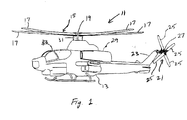
- Figure 1 is an isometric view of a helicopter having a composite flapping flexure according to the present invention.
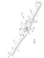
- Figure 2 is an isometric view of a composite flapping flexure according to the present invention used in a rotor yoke application.
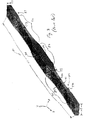
- Figure 3 is an isometric view of a composite flapping flexure test element showing the stacking sequence of a prior art composite flapping flexure;
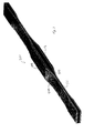
- Figure 4 is an isometric view of a composite flapping flexure test element showing the stacking sequence of the preferred embodiment of the composite flapping flexure of the present invention;
- Figure 5 is computer generated graph of interlaminar shear strain versus flexure angle for the prior-art composite flapping flexure of Figure 1 and the composite flapping flexure according to the present invention of Figure 2;
- Figure 6 is a tabular representation of the results of a test comparison of the prior-art composite flapping flexure of Figure 1 to the composite flapping flexure according to the present invention of Figure 2; and
- Figure 7 is an isometric view of a composite flapping flexure test element showing the stacking sequence of an alternate embodiment of the composite flapping flexure of the present invention.
-
- Referring to Figure 1 in the drawings, an aircraft 11 having a composite flapping flexure according to the present invention is illustrated. Aircraft 11 comprises a fuselage 13 and a
main rotor 15.Main rotor 15 includesrotor blades 17 that are coupled to a pair of stackedrotor yokes 19. Torque imparted to fuselage 13 bymain rotor 15 is counteracted by atail rotor 21 carried by atail portion 23 of fuselage 13.Tail rotor 21 includestail rotor blades 25 and atail rotor hub 27.Main rotor 15 is powered by a drive means 29 via adrive mast 31 under the control of a pilot in acockpit 33. - Referring now to Figure 2 in the drawings, one of the
rotor yokes 19 is illustrated in a perspective view. Yoke 19 incorporatescomposite flapping flexures - Yoke 19 is an elongated member having a
center section 41 and twointegral arm sections center section 41. Yoke 19 will be described herein with reference to orthogonal axes X, Y, and Z, with the Y axis being the longitudinal axis ofyoke 19. Yoke 19 is of laminar construction, preferably being made of a plurality of layers of composite materials, as will be described in detail below. The composite materials that formyoke 19 are layered one upon another, generally in the X-Y plane, and then cured in a conventional manner. Yoke 19 includes anupper surface 47 and alower surface 49. Afteryoke 19 has been laid up and cured,yoke 19 is trimmed to size by conventional means. Other post-cure finishing and machining may be necessary. - Yoke 19 is left with laminated edge surfaces generally parallel to the Z axis that are exposed. These exposed edge surfaces are susceptible to various problems, such as mid-plane delamination that initiates on the exposed edge surface due to edge effect concentrations and that progresses toward the center of the composite flexure as the composite flexure is cyclically loaded; random impact damage, such as from handling; and the uptake moisture in high humidity environments. To alleviate these problems,
protective edge members 51 and 53 are added to the exposed edges ofyoke 19. The functions andoperation edge members 51 and 53 are described in detail in U.S. Patent Application No. 09/407,691, which has been allowed, and which is incorporated herein by reference as if set forth in full. -
Center section 41 ofyoke 19 preferably curves outward in the ±X directions and is thicker in the ±Z directions, thereby providing added volume and strength incenter section 41. Amast aperture 55 is located at the center ofcenter section 41.Mast aperture 55 receivesdrive mast 31.Drive mast 31 is adapted to be coupled toyoke 19 by conventional fastening means, such as bolts (not shown), that pass through a plurality ofbolt apertures 57 that are arranged aroundmast aperture 55.Bolt apertures 57 also provide a means for the second rotor yoke to be coupled to yoke 19. - As
center section 41 transitions intoarm sections yoke 19 tapers inwardly in two directions, X and Z, forming transition regions, referred to herein asflexure regions Flexure regions Flexure regions arm sections aperture 63 passes throughyoke 19 along the Z axis at a point whereflexure region 59 transitions intoarm section 43. Likewise, anaperture 65 passes throughyoke 19 along the Z axis at a point whereflexure region 61 transitions intoarm section 45. Apertures 63 and 65 are adapted and configured to receive conventional elastomeric shear restraint bearings (not shown). It should be understood thatapertures - Continuing with reference to Figure 2 in the drawings,
arm sections flexure regions Arm section 43 may include a plurality of flanges andcurvatures 69. In a symmetrical fashion,arm section 45 may include a plurality of flanges andcurvatures 71. The shape and dimensions of flanges andcurvatures arm sections pitch rotor blades 17. -
Arm section 43 terminates with anend portion 73 havingapertures 75 configured to receive a sleeve member (not shown) that covers the connection of afirst rotor blade 17 toyoke 19. In an identical fashion,arm section 45 terminates with anend portion 77 havingapertures 79 configured to receive a sleeve member (not shown) that covers the connection of asecond rotor blade 17 toyoke 19. The length, thicknesses, and cross-sectional profiles ofyoke 19 are chosen such thatyoke 19 possesses certain selected mechanical properties in selected sections ofyoke 19. As such,yoke 19 is capable of withstanding the centrifugal, feathering, flapping, lead-lag, and other static and dynamic forces and motions generated byrotor blades 17. - Feathering forces and motions are torsional pitch forces and motions generated by the variable pitch of
rotor blades 17; flapping forces and motions are bending forces and motions generated by out-of-plane motion ofrotor blades 17; and lead-lag forces and motions are bending forces and motions generated by in-plane motion ofrotor blades 17. By accommodating the centrifugal, feathering, flapping, lead-lag, and other static and dynamic forces and motions generated byrotor blades 17 solely by selectively determining the length, thicknesses, and cross-sectional profiles ofyoke 19, there is no need for bearings. In other words,yoke 19 may serve as a bearingless helicopter main rotor yoke. - Referring now to Figure 3 in the drawings, a schematic showing the stacking sequence of a prior-art
composite flapping flexure 81 is illustrated. Prior-art flexure 81 will be described herein with reference to orthogonal axes X, Y, and Z, with the Y axis being the longitudinal axis offlexure 81.Flexure 81 is an elongated member having acenter section 83 and twointegral arm sections center section 83.Flexure regions arm sections Flexure 81 typically has a length L1 of about forty-four inches, and a width W1 of about four inches. The thickness offlexure 81 in the Z direction varies along the length offlexure 81. For example,flexure 81 may have a thickness T1 of about 1.25 inches atcenter section 83, a thickness T2 of about 0.375 inches at the midpoints offlexure regions arm sections -
Flexure 81 is of laminar construction, preferably being made of a plurality of layers of composite materials. The composite materials that formflexure 81 are layered one upon another, generally in the X-Y plane, and then cured in a conventional manner.Flexure 81 includes anupper surface 89 and alower surface 91. Afterflexure 81 has been laid up and cured,flexure 81 is trimmed to size by conventional means. Other post-cure finishing and machining may be necessary, such as the addition of mounting apertures and protective edge members (not shown, but similar to edge members 51 and 53), some of which may require a second curing process. - As mentioned above, prior-art composite flapping flexures, such as
flexure 81, are manufactured from composite laminates having layers that alternate between load carrying layers and non-load carrying layers. In the load carrying layers, also referred to as "belts," the fiberglass fibers of the composite material are generally aligned with the longitudinal axis of the flexure, i.e., oriented at 0° to the longitudinal axis. In the non-load carrying layers, also referred to "off-axis layers," the fiberglass fibers are oriented at selected angles to the longitudinal axis of the flexure, such as at ±45°. In Figure 3, a plurality of belts 101 are shown in a light color, and a plurality of off-axis layers 103 are shown in a dark color. As is shown,flexure 81 is arranged from alternating layers of belts 101 and off-axis layers 103, such thatupper surface 89 andlower surface 91 are formed from belts 101, and off-axis layers 103 and additional belts 101 are evenly spaced along the Z direction throughout the interior offlexure 81. Inflexure regions belts 103 typically form about 78% of thickness T2. - Due to fiber orientation, off-
axis layers 103 are softer in bending than belts 101. Whenflexure 81 is subjected to an out-of-plane bending load, shear strains are generated between off-axis layers 103 and belts 101, the maximum shear strain being at the mid-plane in the Z direction offlexure 81. As a result, delamination initiates on the mid-plane, this mid-plane delamination being the predominant failure mode offlexure 81. Becauseflexure 81 is exposed to cyclic bending, failure can result either fromflexure 81 exceeding a certain maximum flexure angle about the X axis, or from fatigue due to the cyclic nature of the bending loads. - Referring now to Figure 4 in the drawings, a schematic showing the preferred stacking sequence of a
composite flapping flexure 201 according to the present invention is illustrated.Flexure 201 will be described herein with reference to orthogonal axes X, Y, and Z, with the Y axis being the longitudinal axis.Flexure 201 is an elongated member having a center section 203 and twointegral arm sections Flexure regions arm sections Flexure 201 preferably has a length L2 of about forty-four inches, and a width W2 of about four inches. The thickness offlexure 201 in the Z direction varies along the length offlexure 201. For example,flexure 201 may have a thickness T4 of about 1.25 inches at center section 203, a thickness T5 of about 0.375 inches atflexure regions arm sections -
Flexure 201 is of laminar construction, preferably being made of a plurality of layers of composite materials. The composite materials that formflexure 201 are layered one upon another, generally in the X-Y plane, and then cured in a conventional manner.Flexure 201 includes anupper surface 209 and a lower surface 211. Afterflexure 201 has been laid up and cured,flexure 201 is trimmed to size by conventional means. Other post-cure finishing and machining may be performed, such as the addition of mounting apertures and protective edge members (not shown, but similar to edge members 51 and 53), some of which may require a second curing process. -
Flexure 201 is manufactured from composite laminates, but is different from prior-art flexure 81 in that load carrying layers, orbelts 213, are preferably disposed only atupper surface 209 and lower surface 211 offlexure 201; and the layers of off-axis material, or off-axis layers 215, are preferably disposed in the interior offlexure 201. In Figure 4,belts 213 are shown in a light color, and off-axis layers 215 are shown in a dark color. Inbelts 213, the fiberglass fibers of the composite material are generally aligned with the longitudinal axis offlexure 201, i.e., at 0° to the longitudinal axis. In off-axis layers 215, the fiberglass fibers are oriented at selected angles to the longitudinal axis of the flexure, preferably at ±45°. Inflexure regions belts 213 typically form about 78% of thickness T5. In the preferred embodiment,belts 213 and off-axis layers 215 are manufactured from fiberglass fibers in an epoxy resin having the designation S2/E773. It should be understood that other composite materials, combinations of S2/E773 and other composite materials, and combinations of completely different composite materials may be used forflexure 201, depending upon particular applications and the particular flexure characteristics desired. - Just as in prior-
art flexure 81, due to fiber orientation, off-axis layers 215 are softer in bending thanbelts 213; and the maximum shear load occurs at the mid-plane offlexure 201 whenflexure 201 experiences bending loads about the X axis. However, because the interfaces betweenbelts 213 and off-axis layers 215 are located very nearupper surface 209 and lower surface 211, whenflexure 201 is subjected to such out-of-plane bending loads, the shear strains generated between off-axis layers 215 andbelts 213 are significantly lower and do not lead to mid-plane delamination. Because the only layers present at the mid-plane offlexure 201 are off-axis layers 215, mid-plane delamination is delayed andflexure 201 does not fail under normal bending loads. In addition,flexure 201 can sustain a higher maximum flexure angle without failing. - Referring now to Figure 5 in the drawings, a computer generated
graph 301 based upon a finite element analysis of prior-artcomposite flapping flexure 81 andcomposite flapping flexure 201 according to the present invention is illustrated. Curve A is a plot of the interlaminar shear strain versus flexure angle for prior-artcomposite flapping flexure 81 of Figure 3, and curve B is a plot of the interlaminar shear strain versus flexure angle for composite flapping flexure 201 of Figure 4. As can be seen, the interlaminar shear strain is higher inflexure 81 for all flexure angles. The higher the interlaminar shear strain, the higher the chance of delamination failure, particularly if the shear strain is located near the mid-plane of the flexure where the shear loads are maximized. These computer generated results are confirmed by actual test results. - Referring now to Figure 6 in the drawings, a tabular representation of actual test results from a comparison of prior-
art flexure 81 toflexure 201 according to the present invention is illustrated. A table 401 includes a row for each of three specimen flexures tested. A row 403 represents test results for a flexure according to the present invention, such asflexure 201, experiencing 27,530 pounds of centrifugal force at a maximum flexure angle of 7°. Next, arow 405 represents test results for a flexure according to the present invention, such asflexure 201, experiencing 27,530 pounds of centrifugal force at a maximum flexure angle of 8°. Finally, a row 407 represents test results for a prior-art flexure, such asflexure 81, experiencing 27,530 pounds of centrifugal force at a maximum flexure angle of 7°. In these tests, the belts form about 78% of the thickness of the flexure region of each flexure. All of the specimens in the test included protective edge members similar toedge members 51 and 53. - As is shown, the prior-art flexure in row 407 experienced an initial mid-plane delamination failure at 356,210 cycles, and experienced a stop failure at 411,918 cycles. On the other hand, the flexure according to the present invention of row 403 did not experience either an initial failure or a stop failure in 10,000,000 cycles; and, when subjected to a heightened maximum flexure angle of 8°, the flexure according to the present invention of
row 405 was able to withstand 4,692,000 cycles before an initial failure, which was also a stop failure. These results indicate that the composite flapping flexure according to the present invention provides significantly greater performance without adding any additional weight or material. Thus, by merely concentrating the load carrying belts at the upper and lower surfaces of the flexure, fatigue failure can be improved, and the maximum flexure angle can be significantly increased. - Referring now to Figure 7 in the drawings, a schematic of an alternate embodiment of the present invention is illustrated. In this embodiment, a
composite flapping flexure 501 has an alternate stacking sequence.Flexure 501 is identical in form and function to flexure 201, in thatbelts 513 are preferably disposed at anupper surface 509 andlower surface 511 offlexure 501; and the layers of off-axis material, or off-axis layers 515, are preferably disposed in the interior offlexure 501; but with the exception that a small number ofbelts 511 are disposed near the mid-plane offlexure 501 for added strength. In Figure 7,belts 513 are shown in a light color, and off-axis layers 215 are shown in a dark color. - It is apparent that an invention with significant advantages has been described and illustrated. Although the present invention is shown in a limited number of forms, it is not limited to just these forms, but is amenable to various changes and modifications without departing from the spirit thereof.
Claims (17)
- A composite flexure for accommodating flapping forces generated by helicopter rotor blades, the composite flexure comprising:an elongated portion having an upper surface, a lower surface, and a longitudinal axis, the elongated portion being adapted for coupling to the rotor blades;a plurality of laminated composite belts having composite fibers that are oriented along the longitudinal axis, the belts extending along the elongated portion and being disposed only at the upper surface and the lower surface; anda plurality of laminated composite off-axis layers having composite fibers that are oriented at selected angles to the longitudinal axis, the off-axis layers extending along the elongated portion and being disposed between the belts.
- The composite flexure according to claim 1, wherein the laminated composite belts and the laminated composite off-axis layers are all formed from fiberglass fibers in an epoxy resin.
- The composite flexure according to claim 1, wherein the laminated composite belts and the laminated composite off-axis layers are all formed from fiberglass fibers in an epoxy resin having a designation S2/E773.
- The composite flexure according to claim 1, wherein the off-axis layers are oriented at ±45° relative to the longitudinal axis.
- The composite flexure according to claim 1, further comprising:a flexure region in each end of the elongated portion, each flexure region having a reduced thickness in a direction perpendicular to the plane of the belts, the reduction in thickness being from a reduction in the number of off-axis layers only.
- The composite flexure according to claim 1, further comprising:protective edge members disposed along exposed lateral edges of the elongated portion.
- A helicopter comprising:wherein the rotor yoke comprises:a fuselage;a drive means carried by the fuselage for actuating a drive mast;a rotor yoke coupled to the drive mast; anda plurality of rotor blades coupled to the rotor yoke(s);wherein flapping forces generated by the rotor blades are accommodated by the flexure regions.an elongated member having an upper surface, a lower surface, a flexure region at each end, and a longitudinal axis;a plurality of laminated composite belts having composite fibers that are oriented along the longitudinal axis, the belts extending along the elongated member and being disposed only at the upper surface and the lower surface; anda plurality of laminated composite off-axis layers having composite fibers that are oriented at selected angles to the longitudinal axis, the off-axis layers extending along the elongated member and being disposed between the belts;
- The helicopter according to claim 7, wherein the laminated composite belts and the laminated composite off-axis layers are all formed from fiberglass fibers in an epoxy resin.
- The helicopter according to claim 7, wherein the laminated composite belts and the laminated composite off-axis layers are all formed from fiberglass fibers in an epoxy resin having a designation S2/E773.
- The helicopter according to claim 7, wherein the off-axis layers are oriented at ±45° relative to the longitudinal axis.
- The helicopter according to claim 7, wherein each flexure region has a reduced thickness in a direction perpendicular to the plane of the belts, the reduction in thickness being from a reduction in the number of off-axis layers only.
- The helicopter according to claim 7, further comprising:
protective edge members disposed along exposed lateral edges of the elongated member. - A method of accommodating flapping forces in a helicopter rotor system, the method comprising the steps of:providing a helicopter having a fuselage and a drive means carried by the fuselage for actuating a drive mast;forming an elongated rotor yoke having an upper surface, a lower surface, a flexure region at each end, and a longitudinal axis, the formation of the rotor yoke comprising the steps of:forming the upper and lower surfaces from a plurality of laminated composite belts having composite fibers that are oriented along the longitudinal axis; anddisposing a plurality of laminated composite off-axis layers having composite fibers that are oriented at selected angles to the longitudinal axis between the belts; andforming the flexure regions by selectively reducing the thickness of the rotor yoke in a direction perpendicular to the plane of the belts, the reduction in thickness being from a reduction in the number of off-axis layers only;
coupling the rotor yoke to the drive mast;
coupling a plurality of rotor blades to the rotor yoke; and
accommodating flapping forces generated by the rotor blades with the flexure regions. - The method according to claim 13, wherein the laminated composite belts and the laminated composite off-axis layers are all formed from fiberglass fibers in an epoxy resin.
- The method according to claim 13, wherein the laminated composite belts and the laminated composite off-axis layers are all formed from fiberglass fibers in an epoxy resin having a designation S2/E773.
- The method according to claim 13, wherein the off-axis layers are oriented at ±45° relative to the longitudinal axis.
- A method to help prevent mid-plane delamination in a composite flapping flexure in a helicopter rotor system, the method comprising the steps of:providing a helicopter having a fuselage and a drive means carried by the fuselage for actuating a drive mast;forming an elongated rotor yoke having an upper surface, a lower surface, a flexure region at each end, and a longitudinal axis, the formation of the rotor yoke comprising the steps of:forming the upper and lower surfaces from a plurality of laminated composite belts having composite fibers that are oriented along the longitudinal axis; anddisposing a plurality of laminated composite off-axis layers having composite fibers that are oriented at selected angles to the longitudinal axis between the belts; andforming the flexure regions by selectively reducing the thickness of the rotor yoke in a direction perpendicular to the plane of the belts, the reduction in thickness being from a reduction in the number of off-axis layers only;
coupling the rotor yoke to the drive shaft; and
coupling a plurality of rotor blades to the rotor yoke.
Applications Claiming Priority (2)
| Application Number | Priority Date | Filing Date | Title |
|---|---|---|---|
| US28525501P | 2001-04-20 | 2001-04-20 | |
| US285255P | 2001-04-20 |
Publications (3)
| Publication Number | Publication Date |
|---|---|
| EP1251068A2 true EP1251068A2 (en) | 2002-10-23 |
| EP1251068A3 EP1251068A3 (en) | 2004-02-04 |
| EP1251068B1 EP1251068B1 (en) | 2005-01-05 |
Family
ID=23093454
Family Applications (1)
| Application Number | Title | Priority Date | Filing Date |
|---|---|---|---|
| EP02076469A Expired - Lifetime EP1251068B1 (en) | 2001-04-20 | 2002-04-16 | Composite flapping flexure |
Country Status (4)
| Country | Link |
|---|---|
| US (1) | US6708921B2 (en) |
| EP (1) | EP1251068B1 (en) |
| CA (1) | CA2381879C (en) |
| DE (2) | DE60202497T2 (en) |
Cited By (3)
| Publication number | Priority date | Publication date | Assignee | Title |
|---|---|---|---|---|
| EP2246259A1 (en) * | 2009-04-29 | 2010-11-03 | Eurocopter Deutschland GmbH | Rotor wing with integrated tension-torque-transmission element and method for its production |
| EP2246256A1 (en) * | 2009-04-29 | 2010-11-03 | Eurocopter Deutschland GmbH | Tension-torque-transmission element for a fenestron blade and method for producing it |
| CN102795338A (en) * | 2012-07-27 | 2012-11-28 | 北京卫星制造厂 | Micro unmanned aerial vehicle carbon fiber rotor wing and preparation method thereof |
Families Citing this family (14)
| Publication number | Priority date | Publication date | Assignee | Title |
|---|---|---|---|---|
| US6708921B2 (en) * | 2001-04-20 | 2004-03-23 | Bell Helicopter Textron, Inc. | Composite flapping flexure |
| US7665969B2 (en) * | 2005-01-24 | 2010-02-23 | Bell Helicopter Textron Inc. | Assembly for providing flexure to blade system |
| EA200801835A1 (en) * | 2006-02-24 | 2009-02-27 | Белл Хеликоптер Текстрон, Инк. | OWNER OF THE SCREW OF THE HELICOPTER AND THE METHOD OF ITS MANUFACTURE |
| EP2246257B1 (en) | 2009-04-29 | 2016-02-17 | AIRBUS HELICOPTERS DEUTSCHLAND GmbH | Multi-section connecting region of a flexbeam |
| WO2011026009A1 (en) | 2009-08-28 | 2011-03-03 | Polystrand, Inc | Thermoplastic rotor blade |
| US9505491B2 (en) * | 2010-08-19 | 2016-11-29 | Sikorsky Aircraft Corporation | Helicopter composite blade spar and method |
| US8602942B2 (en) * | 2011-11-16 | 2013-12-10 | Zee.Aero Inc. | Centrifugal de-clutch |
| US10059438B2 (en) * | 2011-12-26 | 2018-08-28 | Textron Innovations Inc. | Hub assembly with grease lubricated roller bearing and tension-torsion strap |
| EP2772430B1 (en) * | 2013-02-27 | 2016-06-29 | AIRBUS HELICOPTERS DEUTSCHLAND GmbH | Partly cruciform flexbeam and method of manufacturing such a flexbeam |
| US9714086B2 (en) * | 2013-03-13 | 2017-07-25 | Bell Helicopter Textron Inc. | Fiber orientation to allow for automated ply placement with composite rotor yokes |
| US9499262B2 (en) * | 2013-08-02 | 2016-11-22 | Bell Helicopter Textron Inc. | Composite flexure for tiltrotor rotor system |
| US10434687B2 (en) | 2014-12-17 | 2019-10-08 | Sikorsky Aircraft Corporation | Composite laminate tooling and method of forming a composite part using the tooling |
| US11001375B2 (en) * | 2019-03-18 | 2021-05-11 | The Boeing Company | Structurally tunable cores |
| US11155347B2 (en) * | 2019-04-02 | 2021-10-26 | Textron Innovations Inc. | Rotorcraft blade grip |
Family Cites Families (9)
| Publication number | Priority date | Publication date | Assignee | Title |
|---|---|---|---|---|
| US4427340A (en) * | 1982-06-24 | 1984-01-24 | Bell Helicopter Textron Inc. | Soft inplane bearingless helicopter rotor |
| US4741943A (en) | 1985-12-30 | 1988-05-03 | The Boeing Company | Aerodynamic structures of composite construction |
| US4898515A (en) * | 1986-07-23 | 1990-02-06 | United Technologies Corporation | External wrap of composite flexbeam |
| US5358381A (en) * | 1993-03-19 | 1994-10-25 | Bell Helicopter Textron Inc. | Yoke for helicopter rotor systems |
| DE4329744C1 (en) | 1993-09-03 | 1994-09-08 | Deutsche Forsch Luft Raumfahrt | Wing having wing shells made of fibre composite materials, especially carbon fibre composite materials (CFCs), for aircraft |
| JP3631493B2 (en) | 1994-08-31 | 2005-03-23 | ユナイテッド テクノロジーズ コーポレイション | Composite spars for helicopter rotor blades and methods of manufacturing the same |
| US5738494A (en) * | 1996-07-18 | 1998-04-14 | Sikorsky Aircraft Corporation | Optimized composite flexbeam for helicopter rotors |
| US6375426B1 (en) * | 1999-09-28 | 2002-04-23 | Bell Helicopter Textron Inc. | Protective edge members for composite flexures |
| US6708921B2 (en) * | 2001-04-20 | 2004-03-23 | Bell Helicopter Textron, Inc. | Composite flapping flexure |
-
2002
- 2002-04-10 US US10/120,279 patent/US6708921B2/en not_active Expired - Lifetime
- 2002-04-16 DE DE60202497T patent/DE60202497T2/en not_active Expired - Lifetime
- 2002-04-16 DE DE1251068T patent/DE1251068T1/en active Pending
- 2002-04-16 EP EP02076469A patent/EP1251068B1/en not_active Expired - Lifetime
- 2002-04-17 CA CA002381879A patent/CA2381879C/en not_active Expired - Lifetime
Cited By (6)
| Publication number | Priority date | Publication date | Assignee | Title |
|---|---|---|---|---|
| EP2246259A1 (en) * | 2009-04-29 | 2010-11-03 | Eurocopter Deutschland GmbH | Rotor wing with integrated tension-torque-transmission element and method for its production |
| EP2246256A1 (en) * | 2009-04-29 | 2010-11-03 | Eurocopter Deutschland GmbH | Tension-torque-transmission element for a fenestron blade and method for producing it |
| US8834128B2 (en) | 2009-04-29 | 2014-09-16 | Airbus Helicopters Deutschland GmbH | Tension-torque-transmission element for a fenestron blade and method for producing it |
| US8858178B2 (en) | 2009-04-29 | 2014-10-14 | Airbus Helicopters Deutschland GmbH | Rotor wing with integrated tension-torque-transmission element and method for its production |
| CN102795338A (en) * | 2012-07-27 | 2012-11-28 | 北京卫星制造厂 | Micro unmanned aerial vehicle carbon fiber rotor wing and preparation method thereof |
| CN102795338B (en) * | 2012-07-27 | 2014-10-08 | 北京卫星制造厂 | Micro unmanned aerial vehicle carbon fiber rotor wing and preparation method thereof |
Also Published As
| Publication number | Publication date |
|---|---|
| EP1251068A3 (en) | 2004-02-04 |
| EP1251068B1 (en) | 2005-01-05 |
| US6708921B2 (en) | 2004-03-23 |
| CA2381879A1 (en) | 2002-10-20 |
| CA2381879C (en) | 2009-08-11 |
| US20020153450A1 (en) | 2002-10-24 |
| DE1251068T1 (en) | 2003-05-28 |
| DE60202497T2 (en) | 2005-12-22 |
| DE60202497D1 (en) | 2005-02-10 |
Similar Documents
| Publication | Publication Date | Title |
|---|---|---|
| EP1251068B1 (en) | Composite flapping flexure | |
| US4332525A (en) | Matched stiffness rotor flexbeam and blade system | |
| US4536438A (en) | Fibre reinforced composites | |
| US4350728A (en) | Cross reinforcement in a graphite-epoxy laminate | |
| US4898515A (en) | External wrap of composite flexbeam | |
| US5096380A (en) | Composite flexbeam for a bearingless helicopter rotor | |
| EP2296966B1 (en) | Helicopter landing gear with a fiber-reinforced, composite, structural member exhibiting non-linear strain-to-failure | |
| EP3333074A1 (en) | Soft-in-plane proprotor systems | |
| CA2320606C (en) | Protective edge members for composite flexures | |
| EP0600040A1 (en) | Bearingless main rotor assembly torque tube. | |
| EP2868576B1 (en) | Drive link for tiltrotor rotor system | |
| WO2014009314A1 (en) | Reinforcing textile complex for composite parts, and composite parts integrating said complex | |
| US8147198B2 (en) | Helicopter rotor yoke and method of making same | |
| US20180162520A1 (en) | Soft-in-Plane Proprotor Systems | |
| US10870265B2 (en) | Method for limiting interlaminar fatigue in composite laminate and a component incorporating the same | |
| CA2203012A1 (en) | Snubber bearing mounting assembly for bearingless rotors | |
| US10232936B2 (en) | Damper | |
| US9073625B1 (en) | Helicopter rotor yoke | |
| Potluri et al. | Comparison between GFRP and CFRP composite power take-off shaft in helicopters for prescribed torque and geometrical constraints | |
| US11174912B2 (en) | Anti-symmetric spring | |
| US20190203795A1 (en) | Damper | |
| EP0901450B1 (en) | Monolithic structures having improved flaw tolerance | |
| EP3769944B1 (en) | Composite drive shaft under dominant unidirectional torque | |
| CA2055202C (en) | Snubber-bearing with combined elastomer laminates | |
| Sirohi et al. | Development of Mach-scale swashplateless rotor with embedded trailing-edge flaps |
Legal Events
| Date | Code | Title | Description |
|---|---|---|---|
| PUAI | Public reference made under article 153(3) epc to a published international application that has entered the european phase |
Free format text: ORIGINAL CODE: 0009012 |
|
| AK | Designated contracting states |
Kind code of ref document: A2 Designated state(s): AT BE CH CY DE DK ES FI FR GB GR IE IT LI LU MC NL PT SE TR |
|
| AX | Request for extension of the european patent |
Free format text: AL;LT;LV;MK;RO;SI |
|
| EL | Fr: translation of claims filed | ||
| DET | De: translation of patent claims | ||
| PUAL | Search report despatched |
Free format text: ORIGINAL CODE: 0009013 |
|
| AK | Designated contracting states |
Kind code of ref document: A3 Designated state(s): AT BE CH CY DE DK ES FI FR GB GR IE IT LI LU MC NL PT SE TR |
|
| AX | Request for extension of the european patent |
Extension state: AL LT LV MK RO SI |
|
| 17P | Request for examination filed |
Effective date: 20040116 |
|
| GRAP | Despatch of communication of intention to grant a patent |
Free format text: ORIGINAL CODE: EPIDOSNIGR1 |
|
| GRAS | Grant fee paid |
Free format text: ORIGINAL CODE: EPIDOSNIGR3 |
|
| AKX | Designation fees paid |
Designated state(s): DE FR GB IT |
|
| GRAA | (expected) grant |
Free format text: ORIGINAL CODE: 0009210 |
|
| AK | Designated contracting states |
Kind code of ref document: B1 Designated state(s): DE FR GB IT |
|
| REG | Reference to a national code |
Ref country code: GB Ref legal event code: FG4D |
|
| REG | Reference to a national code |
Ref country code: IE Ref legal event code: FG4D |
|
| REF | Corresponds to: |
Ref document number: 60202497 Country of ref document: DE Date of ref document: 20050210 Kind code of ref document: P |
|
| PLBE | No opposition filed within time limit |
Free format text: ORIGINAL CODE: 0009261 |
|
| STAA | Information on the status of an ep patent application or granted ep patent |
Free format text: STATUS: NO OPPOSITION FILED WITHIN TIME LIMIT |
|
| ET | Fr: translation filed | ||
| 26N | No opposition filed |
Effective date: 20051006 |
|
| REG | Reference to a national code |
Ref country code: GB Ref legal event code: FG4D |
|
| REG | Reference to a national code |
Ref country code: FR Ref legal event code: PLFP Year of fee payment: 15 |
|
| REG | Reference to a national code |
Ref country code: FR Ref legal event code: PLFP Year of fee payment: 16 |
|
| REG | Reference to a national code |
Ref country code: FR Ref legal event code: PLFP Year of fee payment: 17 |
|
| PGFP | Annual fee paid to national office [announced via postgrant information from national office to epo] |
Ref country code: DE Payment date: 20190429 Year of fee payment: 18 |
|
| REG | Reference to a national code |
Ref country code: DE Ref legal event code: R119 Ref document number: 60202497 Country of ref document: DE |
|
| PG25 | Lapsed in a contracting state [announced via postgrant information from national office to epo] |
Ref country code: DE Free format text: LAPSE BECAUSE OF NON-PAYMENT OF DUE FEES Effective date: 20201103 |
|
| PGFP | Annual fee paid to national office [announced via postgrant information from national office to epo] |
Ref country code: FR Payment date: 20210426 Year of fee payment: 20 Ref country code: IT Payment date: 20210421 Year of fee payment: 20 |
|
| PGFP | Annual fee paid to national office [announced via postgrant information from national office to epo] |
Ref country code: GB Payment date: 20210427 Year of fee payment: 20 |
|
| REG | Reference to a national code |
Ref country code: GB Ref legal event code: PE20 Expiry date: 20220415 |
|
| PG25 | Lapsed in a contracting state [announced via postgrant information from national office to epo] |
Ref country code: GB Free format text: LAPSE BECAUSE OF EXPIRATION OF PROTECTION Effective date: 20220415 |