EP1251037B1 - Electrical motor system - Google Patents
Electrical motor system Download PDFInfo
- Publication number
- EP1251037B1 EP1251037B1 EP02252691A EP02252691A EP1251037B1 EP 1251037 B1 EP1251037 B1 EP 1251037B1 EP 02252691 A EP02252691 A EP 02252691A EP 02252691 A EP02252691 A EP 02252691A EP 1251037 B1 EP1251037 B1 EP 1251037B1
- Authority
- EP
- European Patent Office
- Prior art keywords
- phase
- power
- recited
- inputs
- pulses
- Prior art date
- Legal status (The legal status is an assumption and is not a legal conclusion. Google has not performed a legal analysis and makes no representation as to the accuracy of the status listed.)
- Expired - Lifetime
Links
Images

Classifications
-
- H—ELECTRICITY
- H02—GENERATION; CONVERSION OR DISTRIBUTION OF ELECTRIC POWER
- H02M—APPARATUS FOR CONVERSION BETWEEN AC AND AC, BETWEEN AC AND DC, OR BETWEEN DC AND DC, AND FOR USE WITH MAINS OR SIMILAR POWER SUPPLY SYSTEMS; CONVERSION OF DC OR AC INPUT POWER INTO SURGE OUTPUT POWER; CONTROL OR REGULATION THEREOF
- H02M7/00—Conversion of AC power input into DC power output; Conversion of DC power input into AC power output
- H02M7/42—Conversion of DC power input into AC power output without possibility of reversal
- H02M7/44—Conversion of DC power input into AC power output without possibility of reversal by static converters
- H02M7/48—Conversion of DC power input into AC power output without possibility of reversal by static converters using discharge tubes with control electrode or semiconductor devices with control electrode
-
- B—PERFORMING OPERATIONS; TRANSPORTING
- B60—VEHICLES IN GENERAL
- B60R—VEHICLES, VEHICLE FITTINGS, OR VEHICLE PARTS, NOT OTHERWISE PROVIDED FOR
- B60R16/00—Electric or fluid circuits specially adapted for vehicles and not otherwise provided for; Arrangement of elements of electric or fluid circuits specially adapted for vehicles and not otherwise provided for
- B60R16/02—Electric or fluid circuits specially adapted for vehicles and not otherwise provided for; Arrangement of elements of electric or fluid circuits specially adapted for vehicles and not otherwise provided for electric constitutive elements
- B60R16/03—Electric or fluid circuits specially adapted for vehicles and not otherwise provided for; Arrangement of elements of electric or fluid circuits specially adapted for vehicles and not otherwise provided for electric constitutive elements for supply of electrical power to vehicle subsystems or for
-
- H—ELECTRICITY
- H02—GENERATION; CONVERSION OR DISTRIBUTION OF ELECTRIC POWER
- H02J—ELECTRIC POWER NETWORKS; CIRCUIT ARRANGEMENTS OR SYSTEMS FOR SUPPLYING OR DISTRIBUTING ELECTRIC POWER; SYSTEMS FOR STORING ELECTRIC ENERGY
- H02J2105/00—Networks for supplying or distributing electric power characterised by their spatial reach or by the load
- H02J2105/30—Networks for supplying or distributing electric power characterised by their spatial reach or by the load the load networks being external to vehicles, i.e. exchanging power with vehicles
- H02J2105/33—Networks for supplying or distributing electric power characterised by their spatial reach or by the load the load networks being external to vehicles, i.e. exchanging power with vehicles exchanging power with road vehicles
-
- H—ELECTRICITY
- H02—GENERATION; CONVERSION OR DISTRIBUTION OF ELECTRIC POWER
- H02J—ELECTRIC POWER NETWORKS; CIRCUIT ARRANGEMENTS OR SYSTEMS FOR SUPPLYING OR DISTRIBUTING ELECTRIC POWER; SYSTEMS FOR STORING ELECTRIC ENERGY
- H02J2207/00—Details of circuit arrangements for charging or discharging batteries or supplying loads from batteries
- H02J2207/20—Charging or discharging characterised by the power electronics converter
Definitions
- This invention relates to an electrical motor system, and in particular a method of incorporating three-phase motors and associated controls into a vehicle.
- Vehicles have been historically equipped with a 12 volt power supply providing direct current. Vehicles have more and more electrical components, and are typically equipped with several motors for powering various accessories. As an example, the windows, the locks, the seats, moon roofs/sun roofs, etc., are all powered by separate motors. Historically, these motors have utilized direct current. In the near future, it is expected that the power supply on vehicles will be increased to 42 volts direct current.
- US4815575 describes a DC motor being supplied by an AC supply with a rectifier and chopper for converting the AC into DC.
- US5896750 discloses using an alternator as a motor in a vehicle by converting DC current to three phase alternating current. This is done by converter 31.
- WO96/10499 discloses use of a windscreen wiper the motor of which has a three phase induction motor powered by a DC voltage battery with a three phase inverter to convert the DC into three phase AC.
- the examples given are of full wave and half wave three phase inverters.
- an electrical motor system in accordance with claim 1.
- Figure 1 shows a circuit 10 having a single controller 12 controlling the flow of current to a plurality of three-phase motors 14, 16 and 18.
- Motors 14, 16 and 18 can be associated with a window 15, a door lock 17 and a mirror 19, shown schematically, in a door module 21.
- the door module is mounted within a vehicle. This only shows suggested applications, and the present invention would extend to a circuit for powering motors at many locations on a vehicle.
- Three power lines 20, 22 and 24 supply the three-phase power.
- a plurality of switches 26, 28 and 30 are associated with each power line 20, 22 and 24, and selectively supply the power to the individual motors 14, 16 and 18.
- Controller 12 is operable to send appropriate control signals through lines 32, 34 and 36 to operate the switches 26, 28 and 30 and to supply power to a selected motor 14, 16 or 18. It should be understood that more than three motors could be associated with this circuit, and it should be understood that the switches 26, 28 and 30 may be as known in the art.
- the switches can be individually actuated, with three separate control lines.
- a single switch element may be controlled by a single control line to achieve the connection of all three power lines. This aspect of the invention thus simplifies the control circuitry for supplying three-phase power to a number of three-phase powered motors.
- a single controller may be utilized, and the controller may be the main control element for the entire vehicle.
- the three-phase power supplied to the motors on a vehicle may be generated by a circuit such as circuit 40 as shown in Figure 2.
- a voltage source 42 which may be a 42 volt power source, or could be a lower voltage power source, supplies voltage to a chopping switch 44.
- the output of this chopping switch 44 is a series of pulses 58.
- a mosfet or other electronic switch can be used as switch 44.
- the series of pulses 58 moves to a power and shift register 56.
- the power and shift register 56 separates the pulses 1, 2 and 3 into phase-shifted current pulses directed through lines 48, 50 and 52 to a motor 46.
- the motor 46 is shown schematically driving an accessory 54 on a vehicle.
- the shift register 56 would be made of known elements capable of turning the pulses 58 into phase-shifted power pulses for the individual lines 48, 50 and 52. Flip flops, and other appropriate circuit elements would be preferably utilized for the shift register 56.
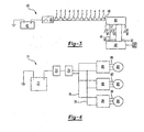
- Figure 3 shows another embodiment 60 wherein a chopping circuit 62 creates a signal 66 having pulse separated into groups of six.
- the wavelets reach a power and shift circuit 64 which alternately reverses the polarity of the output power signals through the lines 48, 50 and 52 as shown in figure.
- Now signals 1 and 4, 2 and 5 and 3 and 6 are di-polar power pulses delivered to power lines 48, 50 and 52.
- circuits shown in Figures 2 and 3 take DC voltage, and create three-phase alternating current. Only simple circuit elements are required, and thus the present invention supplies three-phase current with a relatively inexpensive control package. Thus, the use of the three-phase motors becomes practical with this instant invention.
- Figure 4 shows another circuit 70 wherein the power conversion is performed by a chopping switch 73 and circuit element 74 associated with two power lines 76 and 78.
- the shift registers 86, 90 and 94 convert the signals into the phase-shifted currents for the three-phase wires 88 associated with motor 80, 92 associated with motor 82, and 96 associated with motor 84.
- This invention does not require the power shift to be associated with each motor.
- a circuit such as the circuit shown in Figure 2 or 3 could be associated to supply the power for the lines 20, 22 and 24 in the Figure 1 embodiment.
- the present invention thus reduces the expense and complexity of supplying three-phase power, and controlling that power to flow to appropriate ones of a plurality of motors on a vehicle.
Landscapes
- Engineering & Computer Science (AREA)
- Power Engineering (AREA)
- Control Of Multiple Motors (AREA)
Description
- This invention relates to an electrical motor system, and in particular a method of incorporating three-phase motors and associated controls into a vehicle.
- Vehicles have been historically equipped with a 12 volt power supply providing direct current. Vehicles have more and more electrical components, and are typically equipped with several motors for powering various accessories. As an example, the windows, the locks, the seats, moon roofs/sun roofs, etc., are all powered by separate motors. Historically, these motors have utilized direct current. In the near future, it is expected that the power supply on vehicles will be increased to 42 volts direct current.
- There are motors which are less expensive and smaller than the typical direct current motor. One type of inexpensive and small motor is powered by three-phase alternating current. However, the use of three-phase motors has not been practical in the vehicle environment, since a three-phase power supply has not been practically available in the vehicle. Moreover, three-phase motors typically require associated controls, that would be relatively expensive. Thus, although there would be benefits to utilizing three-phase motors in the vehicle environment, this has not been practically realized.
- US4815575 describes a DC motor being supplied by an AC supply with a rectifier and chopper for converting the AC into DC.
- US5896750 (preamble of claim 1) discloses using an alternator as a motor in a vehicle by converting DC current to three phase alternating current. This is done by converter 31.
- WO96/10499 discloses use of a windscreen wiper the motor of which has a three phase induction motor powered by a DC voltage battery with a three phase inverter to convert the DC into three phase AC. The examples given are of full wave and half wave three phase inverters.
- In a disclosed embodiment of this invention, the use of three-phase motors is made more practical in the vehicle environment.
- According to one aspect of the invention there is provided an electrical motor system in accordance with
claim 1. - These and other features of the present invention can be best understood from the following specification and drawings, the following of which is a brief description.
-
- Figure 1 is a schematic view of a controller for a vehicle.
- Figure 2 is a schematic view of a current generating circuit.
- Figure 3 is a view of a second embodiment current generating circuit.
- Figure 4 is a view of another embodiment.
- Figure 1 shows a
circuit 10 having asingle controller 12 controlling the flow of current to a plurality of three-phase motors Motors window 15, a door lock 17 and amirror 19, shown schematically, in adoor module 21. The door module is mounted within a vehicle. This only shows suggested applications, and the present invention would extend to a circuit for powering motors at many locations on a vehicle. - Three
power lines 20, 22 and 24 supply the three-phase power. A plurality ofswitches power line 20, 22 and 24, and selectively supply the power to theindividual motors Controller 12 is operable to send appropriate control signals throughlines switches motor switches - The three-phase power supplied to the motors on a vehicle may be generated by a circuit such as
circuit 40 as shown in Figure 2. As shown, avoltage source 42, which may be a 42 volt power source, or could be a lower voltage power source, supplies voltage to achopping switch 44. The output of thischopping switch 44 is a series ofpulses 58. A mosfet or other electronic switch can be used asswitch 44. As shown, the series ofpulses 58 moves to a power andshift register 56. The power andshift register 56 separates thepulses lines motor 46. Themotor 46 is shown schematically driving anaccessory 54 on a vehicle. Theshift register 56 would be made of known elements capable of turning thepulses 58 into phase-shifted power pulses for theindividual lines shift register 56. - Figure 3 shows another
embodiment 60 wherein achopping circuit 62 creates asignal 66 having pulse separated into groups of six. The wavelets reach a power andshift circuit 64 which alternately reverses the polarity of the output power signals through thelines power lines - The circuits shown in Figures 2 and 3 take DC voltage, and create three-phase alternating current. Only simple circuit elements are required, and thus the present invention supplies three-phase current with a relatively inexpensive control package. Thus, the use of the three-phase motors becomes practical with this instant invention.
- Figure 4 shows another
circuit 70 wherein the power conversion is performed by achopping switch 73 andcircuit element 74 associated with twopower lines shift registers phase wires 88 associated withmotor motor 82, and 96 associated withmotor 84. This invention does not require the power shift to be associated with each motor. Moreover, a circuit such as the circuit shown in Figure 2 or 3 could be associated to supply the power for thelines 20, 22 and 24 in the Figure 1 embodiment. - The present invention thus reduces the expense and complexity of supplying three-phase power, and controlling that power to flow to appropriate ones of a plurality of motors on a vehicle.
- Although preferred embodiments have been disclosed, a worker in this art would recognize that certain modifications would come within the scope of this invention. For that reason, the following claims should be studied to determine the true scope and content of this invention.
Claims (18)
- An electrical motor system for driving an accessory on a vehicle comprising:at least one three-phase powered motor (14, 16, 18); anda power supply, comprising a direct current voltage source, for supplying three-phase power (20, 22, 24) to three inputs for said three-phase powered motor;characterised in that the system comprises;a chopping switch (44) receiving power from said power supply to create a series of pulses; andat least one phase shift register (56) for receiving and separating said pulses into phase shifted current pulses (48, 50, 52) directed through said inputs to said three-phase powered motor, so that the direct current from the power supply is changed to three phase current that is supplied to said three phase powered motor.
- A system as recited in any preceding claim, wherein said series of pulses comprises three chopped signals and wherein said phase shift register (56) separates said three chopped signals into three phase shifted current pulses (48, 50, 52) with one of said phase shifted current pulses being associated with each of said inputs.
- A system as recited in claim 2 wherein at least one three-phase powered motor comprises a plurality of three-phase powered motors and wherein said three phase shifted current pulses selectively power all of said three-phase powered motors with three-phase power via a system of switches (26, 28, 30).
- A system as recited in Claim 1, wherein said phase shift register creates a di-polar output signal for said inputs.
- A system as recited in Claims 4 wherein said series of pulses are separated into groups of six comprising a first signal, a second signal, a third signal, a fourth signal, a fifth signal, and a sixth signal and wherein said phase shift register (56) alternatively reverses polarity such that said first and fourths signals are a di-polar power pulse delivered to a first of said three inputs, said second and fifth signals are a di-polar power pulse delivered to a second of said three inputs, and said third and sixths signals are a di-polar power pulse delivered to a third of said three inputs.
- A system as recited in any one of Claim 5, wherein said at least one three-phase powered motor comprises a plurality of three-phase powered motors and wherein said first, second and third di-polar power pulses selectively power all of said three-phase powered motors with said three-phase power via a system of switches.
- A system as recited in Claim 1 including a circuit element (74) associated with a pair of power lines (76, 78) that direct power to said phase shift register (86, 90, 94) wherein said circuit element (74) receives said series of pulses from said chopping switch (73).
- A system as recited in claim 7 wherein said at least one three-phase powered motor comprises a plurality of three-phase powered motors (80, 82, 84) and said at least one phase shift register comprises a plurality of phase shift registers with each of said phase shift registers being associated with only one of said three-phase powered motors.
- A system as recited in claim 8 wherein said chopping switch comprises a single chopping switch element (73) and wherein said pair of power lines comprises a first power line (76) operably connecting said circuit element to each of said phase shift registers (86, 90, 94) and a second power line (78) separately connecting said circuit element to each of said phase shift registers such that said single copping switch element and said circuit element provide said series of pulses for receipt by said plurality of phase shift registers (86, 90, 94).
- A system as recited in claim 8 or 9 wherein each of said three-phase powered motors includes three inputs associated with three outputs from a single phase shift register with each of said phase shift registers converting said series of pules into phase shifted currents for said three inputs.
- A system as recited in any preceding claim wherein said at least one three-phase powered motor comprises a plurality of three-phase powered motors with each three-phase powered motor powering a different vehicle accessory and wherein each of said three-phase powered motors includes three inputs for three-phase power.
- A system as recited in any preceding claim wherein said system includes three power lines for supplying three-phase power.
- A system as recited in claim 12 including a switching system having a plurality of switches (26, 28, 30) associated with each of said power lines to selectively supply power to said three-phase powered motors.
- A system as recited in claim 13 including a single controller that controls all of said switches.
- A system as recited in claim 14 wherein said plurality of switches comprises a first set of switches selectively connecting a first of said three power lines to each of a first of said three inputs, a second set of switches selectively connecting a second of said three power lines to each of a second of said three inputs and a third set of switches selectively connecting a third of said three power lines to each of a third of said three inputs.
- A system as recited in Claim 15 wherein each of said three-phase powered motors in operably associated with a door module.
- A system as recited in claim 17 wherein said vehicle accessories include at least a power door lock and a power window.
- A system as recited in claim 1 wherein said power supply comprises a 42-volt power source.
Applications Claiming Priority (2)
| Application Number | Priority Date | Filing Date | Title |
|---|---|---|---|
| US09/836,898 US6538408B2 (en) | 2001-04-17 | 2001-04-17 | Controls to incorporate three-phase motors into vehicles |
| US836898 | 2001-04-17 |
Publications (3)
| Publication Number | Publication Date |
|---|---|
| EP1251037A2 EP1251037A2 (en) | 2002-10-23 |
| EP1251037A3 EP1251037A3 (en) | 2004-05-19 |
| EP1251037B1 true EP1251037B1 (en) | 2007-01-17 |
Family
ID=25273007
Family Applications (1)
| Application Number | Title | Priority Date | Filing Date |
|---|---|---|---|
| EP02252691A Expired - Lifetime EP1251037B1 (en) | 2001-04-17 | 2002-04-16 | Electrical motor system |
Country Status (3)
| Country | Link |
|---|---|
| US (1) | US6538408B2 (en) |
| EP (1) | EP1251037B1 (en) |
| DE (1) | DE60217571T2 (en) |
Families Citing this family (5)
| Publication number | Priority date | Publication date | Assignee | Title |
|---|---|---|---|---|
| DE60215095T2 (en) * | 2001-09-19 | 2007-05-10 | Parker-Hannifin Corp., Cleveland | Motor drive and system |
| US8466652B2 (en) | 2011-01-12 | 2013-06-18 | Arvinmeritor Technology, Llc | Method and apparatus for generating a charging circuit |
| CN102570548B (en) * | 2012-01-10 | 2014-04-09 | 长安大学 | Method for simulating power supply of storage battery and power source for achieving same |
| CN103731071A (en) * | 2012-10-13 | 2014-04-16 | 成都进界科技有限公司 | Mine electric coal drill controller |
| DE102013108156A1 (en) * | 2013-07-30 | 2015-02-05 | BROSE SCHLIEßSYSTEME GMBH & CO. KG | drive arrangement |
Family Cites Families (19)
| Publication number | Priority date | Publication date | Assignee | Title |
|---|---|---|---|---|
| GB1486812A (en) * | 1973-09-03 | 1977-09-28 | Nz Inventions Dev Authority | Waveform synthesis using switching circuits |
| US3970942A (en) * | 1974-04-22 | 1976-07-20 | Sun Oil Company Of Pennsylvania | Anti-hunting system for valve operator circuit |
| US4117364A (en) * | 1976-05-14 | 1978-09-26 | Massachusetts Institute Of Technology | Voltage waveform synthesizer and a system that includes the same |
| US4093905A (en) * | 1976-06-01 | 1978-06-06 | Teletype Corporation | Stepping motor using extended drive pulses |
| US4221001A (en) * | 1977-04-01 | 1980-09-02 | Teletype Corporation | Shift register suitable for controlling the energization of a multiwinding motor |
| JPS5517230A (en) * | 1978-07-21 | 1980-02-06 | Hitachi Ltd | Control device for electric motor car |
| US4815575A (en) * | 1988-04-04 | 1989-03-28 | General Motors Corporation | Electric, variable damping vehicle suspension |
| US5355061A (en) * | 1992-01-24 | 1994-10-11 | Grimes Aerospace Company | Windshield wiper system |
| DE4202083C2 (en) * | 1992-01-25 | 1994-01-20 | Daimler Benz Ag | Hybrid drive for a motor vehicle |
| KR100234731B1 (en) * | 1992-02-21 | 1999-12-15 | 구자홍 | Position detecting device of a srm |
| DE4300760A1 (en) * | 1993-01-14 | 1994-07-21 | Philips Patentverwaltung | Circuit arrangement for commutating a collectorless DC motor |
| US5642026A (en) * | 1994-09-30 | 1997-06-24 | Itt Automotive Electrical Systems, Inc. | Windshield wiper system having reduced wipe speed at reversal points using variable frequency induction motor control |
| FR2727902A1 (en) * | 1994-12-09 | 1996-06-14 | Valeo Thermique Habitacle | DEVICE FOR AIR CONDITIONING A VEHICLE IN TRAFFIC AND PARKING |
| JP3399134B2 (en) * | 1994-12-12 | 2003-04-21 | 株式会社明電舎 | Operation control device for pole number switching motor |
| US5629567A (en) * | 1995-06-26 | 1997-05-13 | General Electric Company | Speed control system for an AC locomotive |
| DE19617165A1 (en) * | 1996-04-29 | 1997-10-30 | Siemens Ag | Chassis for commercial vehicle with rigid axle i.e. for diesel electric town bus |
| DE19636679C2 (en) * | 1996-09-10 | 1999-05-20 | Ernst Gaus | Air conditioner for vehicle cabins |
| US5903115A (en) * | 1997-11-24 | 1999-05-11 | Alliedsignal Inc. | Auxiliary system including a plurality of ac motors powered directly by an electric generator |
| DE10014226A1 (en) * | 2000-03-22 | 2001-09-27 | Bosch Gmbh Robert | Electromechanical wheel brake has transversal flux motor with annular stimulation winding enclosing axis, yokes distributed peripherally on stimulation winding, matching movable poles |
-
2001
- 2001-04-17 US US09/836,898 patent/US6538408B2/en not_active Expired - Fee Related
-
2002
- 2002-04-16 EP EP02252691A patent/EP1251037B1/en not_active Expired - Lifetime
- 2002-04-16 DE DE60217571T patent/DE60217571T2/en not_active Expired - Fee Related
Also Published As
| Publication number | Publication date |
|---|---|
| US20020149339A1 (en) | 2002-10-17 |
| DE60217571T2 (en) | 2007-10-25 |
| EP1251037A2 (en) | 2002-10-23 |
| US6538408B2 (en) | 2003-03-25 |
| DE60217571D1 (en) | 2007-03-08 |
| EP1251037A3 (en) | 2004-05-19 |
Similar Documents
| Publication | Publication Date | Title |
|---|---|---|
| US5517401A (en) | Three level pulse width modulated inverter for an electric vehicle | |
| JP2834465B2 (en) | Vehicle power system equipment | |
| US20050122082A1 (en) | Drive system | |
| US5175439A (en) | Power supply circuit for motor vehicles | |
| JP5754597B2 (en) | Electrical system for starting aircraft engines | |
| US9035578B2 (en) | System for coupling at least one DC source to a controllable energy store and associated operating method | |
| US20020070715A1 (en) | Mechanical power outputting apparatus and inverter apparatus | |
| EP3988377B1 (en) | A vehicle electrical system | |
| US7023171B2 (en) | Integrated inverter for driving multiple electric machines | |
| JP3135581B2 (en) | Automotive network | |
| US7202625B2 (en) | Multi-motor switched reluctance traction system | |
| US6548916B1 (en) | Power supply system and power supply method | |
| JP2005073399A (en) | Power supply device and automobile equipped with the same | |
| US6538408B2 (en) | Controls to incorporate three-phase motors into vehicles | |
| US6404150B1 (en) | Accessory motor drive power supply system for an electric vehicle | |
| EP1815585A1 (en) | Method and system for producing controlled frequency power from a variable frequency power source | |
| JP2755640B2 (en) | In-vehicle power supply | |
| JPH066910A (en) | Electric traction system for automobile | |
| EP0555773A1 (en) | Inverter for electric vehicle | |
| US5485064A (en) | Self-synchronous motor and electrical traction system using a self-synchronous motor | |
| US6853159B2 (en) | Apparatus and method for generating torque | |
| US20240154558A1 (en) | Converter, and method for the operation of a converter | |
| KR101857781B1 (en) | Power converting apparatus performing function of inverter | |
| EP1249927A2 (en) | Method and system for converting single phase alternating current to multiple phase alternating current | |
| JP4153760B2 (en) | Motor circuit and motor control method |
Legal Events
| Date | Code | Title | Description |
|---|---|---|---|
| PUAI | Public reference made under article 153(3) epc to a published international application that has entered the european phase |
Free format text: ORIGINAL CODE: 0009012 |
|
| AK | Designated contracting states |
Kind code of ref document: A2 Designated state(s): AT BE CH CY DE DK ES FI FR GB GR IE IT LI LU MC NL PT SE TR |
|
| AX | Request for extension of the european patent |
Free format text: AL;LT;LV;MK;RO;SI |
|
| PUAL | Search report despatched |
Free format text: ORIGINAL CODE: 0009013 |
|
| AK | Designated contracting states |
Kind code of ref document: A3 Designated state(s): AT BE CH CY DE DK ES FI FR GB GR IE IT LI LU MC NL PT SE TR |
|
| AX | Request for extension of the european patent |
Extension state: AL LT LV MK RO SI |
|
| RIC1 | Information provided on ipc code assigned before grant |
Ipc: 7B 60R 16/00 B Ipc: 7B 60R 16/02 A Ipc: 7H 02M 7/48 B Ipc: 7H 02J 7/00 B |
|
| 17P | Request for examination filed |
Effective date: 20040906 |
|
| AKX | Designation fees paid |
Designated state(s): DE ES FR GB IT |
|
| 17Q | First examination report despatched |
Effective date: 20050628 |
|
| RAP1 | Party data changed (applicant data changed or rights of an application transferred) |
Owner name: ARVINMERITOR TECHNOLOGY, LLC |
|
| GRAP | Despatch of communication of intention to grant a patent |
Free format text: ORIGINAL CODE: EPIDOSNIGR1 |
|
| GRAS | Grant fee paid |
Free format text: ORIGINAL CODE: EPIDOSNIGR3 |
|
| GRAA | (expected) grant |
Free format text: ORIGINAL CODE: 0009210 |
|
| AK | Designated contracting states |
Kind code of ref document: B1 Designated state(s): DE ES FR GB IT |
|
| REG | Reference to a national code |
Ref country code: GB Ref legal event code: FG4D |
|
| REF | Corresponds to: |
Ref document number: 60217571 Country of ref document: DE Date of ref document: 20070308 Kind code of ref document: P |
|
| PG25 | Lapsed in a contracting state [announced via postgrant information from national office to epo] |
Ref country code: ES Free format text: LAPSE BECAUSE OF FAILURE TO SUBMIT A TRANSLATION OF THE DESCRIPTION OR TO PAY THE FEE WITHIN THE PRESCRIBED TIME-LIMIT Effective date: 20070428 |
|
| PGFP | Annual fee paid to national office [announced via postgrant information from national office to epo] |
Ref country code: DE Payment date: 20070517 Year of fee payment: 6 |
|
| PLBE | No opposition filed within time limit |
Free format text: ORIGINAL CODE: 0009261 |
|
| STAA | Information on the status of an ep patent application or granted ep patent |
Free format text: STATUS: NO OPPOSITION FILED WITHIN TIME LIMIT |
|
| 26N | No opposition filed |
Effective date: 20071018 |
|
| GBPC | Gb: european patent ceased through non-payment of renewal fee |
Effective date: 20070417 |
|
| PG25 | Lapsed in a contracting state [announced via postgrant information from national office to epo] |
Ref country code: FR Free format text: LAPSE BECAUSE OF FAILURE TO SUBMIT A TRANSLATION OF THE DESCRIPTION OR TO PAY THE FEE WITHIN THE PRESCRIBED TIME-LIMIT Effective date: 20070907 Ref country code: GB Free format text: LAPSE BECAUSE OF NON-PAYMENT OF DUE FEES Effective date: 20070417 |
|
| PG25 | Lapsed in a contracting state [announced via postgrant information from national office to epo] |
Ref country code: FR Free format text: LAPSE BECAUSE OF FAILURE TO SUBMIT A TRANSLATION OF THE DESCRIPTION OR TO PAY THE FEE WITHIN THE PRESCRIBED TIME-LIMIT Effective date: 20070117 |
|
| PG25 | Lapsed in a contracting state [announced via postgrant information from national office to epo] |
Ref country code: DE Free format text: LAPSE BECAUSE OF NON-PAYMENT OF DUE FEES Effective date: 20081101 |
|
| PG25 | Lapsed in a contracting state [announced via postgrant information from national office to epo] |
Ref country code: IT Free format text: LAPSE BECAUSE OF NON-PAYMENT OF DUE FEES Effective date: 20070430 |