EP1250966A1 - Suction unit and powder coating booth with an automatic bottom filter - Google Patents
Suction unit and powder coating booth with an automatic bottom filter Download PDFInfo
- Publication number
- EP1250966A1 EP1250966A1 EP02076391A EP02076391A EP1250966A1 EP 1250966 A1 EP1250966 A1 EP 1250966A1 EP 02076391 A EP02076391 A EP 02076391A EP 02076391 A EP02076391 A EP 02076391A EP 1250966 A1 EP1250966 A1 EP 1250966A1
- Authority
- EP
- European Patent Office
- Prior art keywords
- filter
- web
- filtration
- floor
- filter web
- Prior art date
- Legal status (The legal status is an assumption and is not a legal conclusion. Google has not performed a legal analysis and makes no representation as to the accuracy of the status listed.)
- Withdrawn
Links
- 239000000843 powder Substances 0.000 title description 2
- 239000011248 coating agent Substances 0.000 title 1
- 238000000576 coating method Methods 0.000 title 1
- 238000001914 filtration Methods 0.000 claims abstract description 22
- 239000000463 material Substances 0.000 claims abstract description 6
- 239000002245 particle Substances 0.000 claims abstract description 5
- 239000000835 fiber Substances 0.000 claims 1
- 238000005507 spraying Methods 0.000 description 11
- 239000003973 paint Substances 0.000 description 9
- 239000007921 spray Substances 0.000 description 6
- 239000000428 dust Substances 0.000 description 4
- 238000010422 painting Methods 0.000 description 2
- XLYOFNOQVPJJNP-UHFFFAOYSA-N water Substances O XLYOFNOQVPJJNP-UHFFFAOYSA-N 0.000 description 2
- 238000007664 blowing Methods 0.000 description 1
- 238000004880 explosion Methods 0.000 description 1
- 239000012065 filter cake Substances 0.000 description 1
- 238000002360 preparation method Methods 0.000 description 1
- 238000002203 pretreatment Methods 0.000 description 1
- 229920006395 saturated elastomer Polymers 0.000 description 1
- 239000002904 solvent Substances 0.000 description 1
- 230000003068 static effect Effects 0.000 description 1
- 238000009423 ventilation Methods 0.000 description 1
- 238000004804 winding Methods 0.000 description 1
Images

Classifications
-
- B—PERFORMING OPERATIONS; TRANSPORTING
- B01—PHYSICAL OR CHEMICAL PROCESSES OR APPARATUS IN GENERAL
- B01D—SEPARATION
- B01D46/00—Filters or filtering processes specially modified for separating dispersed particles from gases or vapours
- B01D46/18—Particle separators, e.g. dust precipitators, using filtering belts
-
- B—PERFORMING OPERATIONS; TRANSPORTING
- B05—SPRAYING OR ATOMISING IN GENERAL; APPLYING FLUENT MATERIALS TO SURFACES, IN GENERAL
- B05B—SPRAYING APPARATUS; ATOMISING APPARATUS; NOZZLES
- B05B14/00—Arrangements for collecting, re-using or eliminating excess spraying material
- B05B14/40—Arrangements for collecting, re-using or eliminating excess spraying material for use in spray booths
- B05B14/43—Arrangements for collecting, re-using or eliminating excess spraying material for use in spray booths by filtering the air charged with excess material
-
- F—MECHANICAL ENGINEERING; LIGHTING; HEATING; WEAPONS; BLASTING
- F26—DRYING
- F26B—DRYING SOLID MATERIALS OR OBJECTS BY REMOVING LIQUID THEREFROM
- F26B25/00—Details of general application not covered by group F26B21/00 or F26B23/00
- F26B25/005—Treatment of dryer exhaust gases
- F26B25/007—Dust filtering; Exhaust dust filters
-
- B—PERFORMING OPERATIONS; TRANSPORTING
- B01—PHYSICAL OR CHEMICAL PROCESSES OR APPARATUS IN GENERAL
- B01D—SEPARATION
- B01D2275/00—Filter media structures for filters specially adapted for separating dispersed particles from gases or vapours
- B01D2275/30—Porosity of filtering material
- B01D2275/305—Porosity decreasing in flow direction
Definitions
- Such a spraying apparatus is known from the Belgian patent nr 1 009 345 of applicant.
- the particles carried with the air stream in this spraying apparatus are catched or entrapped in porous filter webs which are mounted under the floor grids.
- the purified air under the filters is then removed by suction by a ventilator and is delivered further in the open air.
- This so-called dry filtration process with this known filtration apparatus has i. a. the important disadvantage that the static or fixed filters are to be exchanged manually from time to time, especially when they are loaded and saturated with spray rests. This manual operation is however cumbersome, it takes a lot of time, and it is also unsafe because of the open channel areas in the floor during the exchange operation.
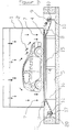
- Figure 1 shows a schematic view of a spraying booth.
- Figure 2 is an view of a longitudinal section of this booth, according to figure 1.
- the air flow 7 loaded with paint rests or dust is removed by suction by means of a ventilator 6 through the floor grids 4 in the channel 5 under the floor.
- the filter material just below the floor grids 4 is in the form of a filter web 8. This web is suitably supported by a perforated plate 15 which is mounted on a supporting frame 16 in the channel 5.
- the degree of load or blockage of the filter web 8 can be defined by measuring the pressure drop accross the filter web. If the pressure drop increases to the maximum allowed value, a signal can be given in a usual manner to the operator in the spraying booth to replace the filter web in section 14 and thus to wind up the filter for that purpose. This can possibly also be done automatically by linking the signal to the turning on and off of the electric drive 13 operating via a motor reductor combination. With an air velocity through the filter web of 0,7 up to 1,5 m/sec, the pressure drop in the section 14 over a filter web 8 with the said high porosity may increase up to approximately 80 Pa before replacement. At that moment, the paint loaded web has absorbed about 4 kg of paint rests per m 2 .
Landscapes
- Engineering & Computer Science (AREA)
- Mechanical Engineering (AREA)
- General Engineering & Computer Science (AREA)
- Chemical & Material Sciences (AREA)
- Chemical Kinetics & Catalysis (AREA)
- Details Or Accessories Of Spraying Plant Or Apparatus (AREA)
Abstract
The invention relates to an apparatus for filtration comprising a device for exchanging air
filters in treating rooms (1) for objects (2) wherein suitable grids (4) are provided in the
floor (3) of the room that give access to one or more discharge channels (5) under the
floor. In those channels suction means (6) are provided for an air circulation stream (7).
The apparatus for filtration with replaceable filter material for the purpose of catching
particles carried with the air stream, comprises a filter web (8) that is fixed at one of its
extremities to a take-up drum (10) for the loaded filter. The web (8) is near its other
extremity rotatably mounted and wound up as a roll for a fresh filter stock (11). The filter
web can be moved through the filtration section (14) by driving means (13).
Description
- The invention relates to an apparatus for filtration, including a device for exchanging air filters, by treating objects with a forced air circulation in a room or booth, as e.g. in sanding, respectively in spraying booths for the preparation, respectively painting or lacquering of objects. It relates also to a treating room that is equiped with such a filtration apparatus.
- It is known to paint objects, e.g. car bodies by means of spray guns in spraying booths after a sanding operation. In de booth where the paint is sprayed by the spray guns on the objects a downward air flow is generally present. It is the purpose of this laminar downward flow around the object to drain the spray rests, which do not settle down on the object, downwards with the air stream through suitable grids in the floor of the room. The forced air flow is mostly generated by a suitable ventilator in a channel downstream of said floor grids.
- Such a spraying apparatus is known from the
Belgian patent nr 1 009 345 of applicant.
The particles carried with the air stream in this spraying apparatus are catched or entrapped in porous filter webs which are mounted under the floor grids. The purified air under the filters is then removed by suction by a ventilator and is delivered further in the open air. This so-called dry filtration process with this known filtration apparatus has i. a. the important disadvantage that the static or fixed filters are to be exchanged manually from time to time, especially when they are loaded and saturated with spray rests. This manual operation is however cumbersome, it takes a lot of time, and it is also unsafe because of the open channel areas in the floor during the exchange operation. This is an imporant disadvantage, especially with spraying booths that are practically continuously in use. Therefore, for these intensively used spraying booths, people switched over to the application of water curtains which then carried the paint residue particles away. However, this last solution requires an additional water-treatment plant. That's why people want to come back to dry filtration, also for continuously used treating rooms. - The invention avoids now these disadvantages by offering an apparatus for filtration that allows an easier exchange of the air filters in treating rooms of objects for wich in the floor of the room grids have been mounted, that give access to one or more discharge channels under the floor. In these channels suction means are provided to create and maintain an air circulation stream. The apparatus for filtration with the replaceable filter material to catch the particles that are carried away by the air flow is also placed in these channels.
- According to the invention, the filter material comprises at least one filter web that is fixed at one of its extremities to a take-up drum that is rotatably mounted around its shaft, and at its other extremity is rotatably mounted and wound up as a roll for a fresh filter stock. Driving means are also provided for delivering and moving the filter web through the filtration section between the stock roll (from which the fresh filter web is delivered or wound off) and the take-up drum for the loaded filter web.
- The filtration section can be placed or extend at a certain distance under the floor grids. However the section preferably extends near the underside of the floor grids. In this section, the wound off filter web is preferably supported by a perforated chute or gutter.
- The filter web has, preferably, a very high porosity, as e.g. with depth filters, so that a lot of paint residue can be taken up before the pressure drop accross the web in the filtration section becomes too high. An average porosity of 99 tot 99,9 % in the filtration section - and by preference at the same time a filter thickness between 4 and 7 cm - is appropriate. With the application of a depth filter with such a high porosity, a certain strength is desirable for the web at its outlet side in view of an easy wind-off and wind-up operation. The porosity at this outlet side will thus preferably be smaller than at the inlet side. However surface filters (with a higher density than depth filters) can now also be used more easily. They have to be exchanged more often than depth filters, but the use of filter webs that can be rolled up, just enables an easy exchange. The filter cake of paint residue built up on the filter web of surface filters can also be partly scraped off at the take-up drum, just before winding up the loaded filter web.
- An embodiment of this apparatus according to the invention and its operation will now be illustrated by way of example and with reference to the accompanying drawings.
- Figure 1 shows a schematic view of a spraying booth.
Figure 2 is an view of a longitudinal section of this booth, according to figure 1. - A car 2 is placed upon the
floor grids 4 in a spraying - orsanding booth 1 for car bodies. In case of painting or lacquering in a spraying booth or of blowing off abrasive powder or dust in pre-treatment areas with compressed air, one should make sure, because of ergonomic reasons, that the sprayed paint solution or the dust does not return back in a turbulent movement to the operator of the spray gun, respectively the compressed air gun : theair flow 7 should drain the spray rests or residue downwards and away from the operator. The clouds of dust produced in the sanding areas should be drained off similarly. - The
air flow 7 loaded with paint rests or dust is removed by suction by means of a ventilator 6 through thefloor grids 4 in the channel 5 under the floor. is The filter material just below thefloor grids 4 is in the form of afilter web 8. This web is suitably supported by aperforated plate 15 which is mounted on a supportingframe 16 in the channel 5. - A
stock 11 of thefilter web 8 is wound up as a roll on arotatable shaft 12 that is carried in bearings in asuitable framework 17 at one of the extremities of channel 5. The fresh filter stock or supply roll 11 (without shaft) can also be put in a concavelyshaped support 20. From this stock thefilter web 8 proceeds through the filtration section 14 over the chute orgutter 15 under the accompanyingfloor grid 4 to the take-up drum 10. Thisdrum 10 is mounted on ashaft 9 which is carried in bearings in aframe 18 in channel 5. The take-up drum 10 can be driven by a crank-shaft 19 if desired, and after a certain spraying time, the loadedfilter web 8 in the section 14 can be wound up on theroll 10 over the longitudinal distance or length of this section. At the same time a fresh section offilter web 8 is rolled off from the freshfilter stock roll 11 and moved over thechute 15. - The degree of load or blockage of the
filter web 8 can be defined by measuring the pressure drop accross the filter web. If the pressure drop increases to the maximum allowed value, a signal can be given in a usual manner to the operator in the spraying booth to replace the filter web in section 14 and thus to wind up the filter for that purpose. This can possibly also be done automatically by linking the signal to the turning on and off of theelectric drive 13 operating via a motor reductor combination. With an air velocity through the filter web of 0,7 up to 1,5 m/sec, the pressure drop in the section 14 over afilter web 8 with the said high porosity may increase up to approximately 80 Pa before replacement. At that moment, the paint loaded web has absorbed about 4 kg of paint rests per m2. - The exhaust ventilators 6 beyond channel 5 take care of a sufficient suction and ventilation capacity, preferably around the filtration section 14 or around the take-
up drums 10 to drain away possible solvent vapours in this environment, as soon and as complete as possible, e.g. to avoid the risk of explosions. - The invention is of course not limited to the above described embodiment, but it also covers mechanically equivalent variants thereof.
Claims (9)
- An apparatus for filtration comprising a device for exchanging air filters in treating rooms (1) for objects (2) wherein suitable grids (4) are provided in the floor (3) of the room that give access tot one or more channels (5) under the floor, whereby in those channels suction means (6) are provided for an air circulation stream (7) and wherein, for the purpose of catching particles carried with the air stream, a filter material is placed in these channels between said grids (4) and the suction means, characterised in that the filter material comprises at least one filter web (8) that is fixed at one of its extremities to a take-up drum (10) for the loaded filter, which drum is rotatably mounted around its shaft (9), and at its other extremity is rotatably mounted and wound up as a roll for a fresh filter stock (11), and that driving means (13) are provided for delivering and moving the filter web through the filtration section (14) between the stock roll and the take-up drum.
- An apparatus according to claim 1 in which the filtration section (14) extends near the underside of the floor grids (4).
- An apparatus according to claim 1 or 2 in which the wound off filter web in the filtration section (14) is supported by a perforated chute (15).
- An apparatus according to one or another of the preceding claims in which the wound off filter web in the filtration section comprises a non-woven fibre web with an average porosity between 99 % and 99,9 %.
- An apparatus according to claim 4 in which the filter web has a thickness between 4 and 7 cm.
- An apparatus according to one or another of the preceding claims in which the filter web is a depth filter.
- An apparatus according to claim 6 in which the porosity near the filter outlet side of the filter web is smaller than near the filter inlet side.
- An apparatus according to one or another of the claims 1 to 3 in which the filter web is a surface filter.
- A treatment room (1) for objects (2) equipped with an apparatus for filtration according to one or another of the preceding claims.
Applications Claiming Priority (2)
| Application Number | Priority Date | Filing Date | Title |
|---|---|---|---|
| BE200100242 | 2001-04-09 | ||
| BE2001/0242A BE1014468A3 (en) | 2001-04-09 | 2001-04-09 | Filter device. |
Publications (1)
| Publication Number | Publication Date |
|---|---|
| EP1250966A1 true EP1250966A1 (en) | 2002-10-23 |
Family
ID=3896934
Family Applications (1)
| Application Number | Title | Priority Date | Filing Date |
|---|---|---|---|
| EP02076391A Withdrawn EP1250966A1 (en) | 2001-04-09 | 2002-04-09 | Suction unit and powder coating booth with an automatic bottom filter |
Country Status (2)
| Country | Link |
|---|---|
| EP (1) | EP1250966A1 (en) |
| BE (1) | BE1014468A3 (en) |
Cited By (8)
| Publication number | Priority date | Publication date | Assignee | Title |
|---|---|---|---|---|
| ITMI20100014A1 (en) * | 2010-01-11 | 2011-07-12 | Cias Nord S R L | FILTER UNIT PARTICULARLY FOR PAINTING CABINS. |
| ITMI20100635A1 (en) * | 2010-04-14 | 2011-10-15 | Elmag Spa | "DRY FILTERING DEVICE FOR OVER SPRAY" |
| CN102367200A (en) * | 2011-09-06 | 2012-03-07 | 安徽科宏玻璃机械有限公司 | Lacquering chamber |
| JP2013154259A (en) * | 2012-01-26 | 2013-08-15 | Taikisha Ltd | Adhesive material collection equipment |
| JP2013166118A (en) * | 2012-02-15 | 2013-08-29 | Taikisha Ltd | Adhesive substance collection equipment |
| WO2016116393A1 (en) * | 2015-01-22 | 2016-07-28 | Jens Neumann | Filter changing device and method for the operation thereof |
| CN109013128A (en) * | 2018-10-30 | 2018-12-18 | 江苏同和智能装备有限公司 | A kind of paint spray booth's carton apparatus for automatic change and application method |
| US20220193595A1 (en) * | 2020-12-17 | 2022-06-23 | Jung-Tsung Wei | Waste gas purification system |
Citations (8)
| Publication number | Priority date | Publication date | Assignee | Title |
|---|---|---|---|---|
| GB806680A (en) * | 1957-02-06 | 1958-12-31 | Sheila Forshee | Method and means for trapping paint over-spray |
| US3811371A (en) * | 1970-09-28 | 1974-05-21 | S Hardy | Paint spray booth |
| US4011067A (en) * | 1974-01-30 | 1977-03-08 | Minnesota Mining And Manufacturing Company | Filter medium layered between supporting layers |
| DE7808580U1 (en) * | 1978-03-21 | 1980-03-06 | Rapp, Herbert, 7401 Pliezhausen | Electrostatic powder coating device |
| US4221576A (en) * | 1979-01-19 | 1980-09-09 | James M. Perrier, Sr. | Automatic air filter changer |
| US4229187A (en) * | 1979-04-09 | 1980-10-21 | Gamewell Manufacturing, Inc. | Movable, continuously changing, self-charging electrostatic filter |
| US4530274A (en) * | 1980-03-12 | 1985-07-23 | Lyons Robert E | Process and apparatus for filtering spray coating particles from air |
| US4647298A (en) * | 1983-09-08 | 1987-03-03 | Peter Ribnitz | Electrostatic powder recovery installation |
-
2001
- 2001-04-09 BE BE2001/0242A patent/BE1014468A3/en not_active IP Right Cessation
-
2002
- 2002-04-09 EP EP02076391A patent/EP1250966A1/en not_active Withdrawn
Patent Citations (8)
| Publication number | Priority date | Publication date | Assignee | Title |
|---|---|---|---|---|
| GB806680A (en) * | 1957-02-06 | 1958-12-31 | Sheila Forshee | Method and means for trapping paint over-spray |
| US3811371A (en) * | 1970-09-28 | 1974-05-21 | S Hardy | Paint spray booth |
| US4011067A (en) * | 1974-01-30 | 1977-03-08 | Minnesota Mining And Manufacturing Company | Filter medium layered between supporting layers |
| DE7808580U1 (en) * | 1978-03-21 | 1980-03-06 | Rapp, Herbert, 7401 Pliezhausen | Electrostatic powder coating device |
| US4221576A (en) * | 1979-01-19 | 1980-09-09 | James M. Perrier, Sr. | Automatic air filter changer |
| US4229187A (en) * | 1979-04-09 | 1980-10-21 | Gamewell Manufacturing, Inc. | Movable, continuously changing, self-charging electrostatic filter |
| US4530274A (en) * | 1980-03-12 | 1985-07-23 | Lyons Robert E | Process and apparatus for filtering spray coating particles from air |
| US4647298A (en) * | 1983-09-08 | 1987-03-03 | Peter Ribnitz | Electrostatic powder recovery installation |
Cited By (12)
| Publication number | Priority date | Publication date | Assignee | Title |
|---|---|---|---|---|
| ITMI20100014A1 (en) * | 2010-01-11 | 2011-07-12 | Cias Nord S R L | FILTER UNIT PARTICULARLY FOR PAINTING CABINS. |
| ITMI20100635A1 (en) * | 2010-04-14 | 2011-10-15 | Elmag Spa | "DRY FILTERING DEVICE FOR OVER SPRAY" |
| CN102367200A (en) * | 2011-09-06 | 2012-03-07 | 安徽科宏玻璃机械有限公司 | Lacquering chamber |
| JP2013154259A (en) * | 2012-01-26 | 2013-08-15 | Taikisha Ltd | Adhesive material collection equipment |
| JP2013166118A (en) * | 2012-02-15 | 2013-08-29 | Taikisha Ltd | Adhesive substance collection equipment |
| WO2016116393A1 (en) * | 2015-01-22 | 2016-07-28 | Jens Neumann | Filter changing device and method for the operation thereof |
| EP3062909B1 (en) | 2015-01-22 | 2017-02-15 | Jens Neumann | Filter changing device and method for the operation thereof |
| CN109013128A (en) * | 2018-10-30 | 2018-12-18 | 江苏同和智能装备有限公司 | A kind of paint spray booth's carton apparatus for automatic change and application method |
| US20220193595A1 (en) * | 2020-12-17 | 2022-06-23 | Jung-Tsung Wei | Waste gas purification system |
| US20220193594A1 (en) * | 2020-12-17 | 2022-06-23 | Jung-Tsung Wei | Waste gas purification system |
| US11826692B2 (en) * | 2020-12-17 | 2023-11-28 | Jung-Tsung Wei | Waste gas purification system |
| US12042760B2 (en) * | 2020-12-17 | 2024-07-23 | Jung-Tsung Wei | Waste gas purification system |
Also Published As
| Publication number | Publication date |
|---|---|
| BE1014468A3 (en) | 2003-11-04 |
Similar Documents
| Publication | Publication Date | Title |
|---|---|---|
| RU2392062C2 (en) | Device for removal of paint mist formed by liquid varnish | |
| EP2736655B1 (en) | Compact painting facility | |
| US4926746A (en) | Work chamber with shifting ventilation zone | |
| US3252401A (en) | Paint spray booth apparatus and method | |
| JP2904912B2 (en) | Spray booth and control device and control method therefor | |
| EP1250966A1 (en) | Suction unit and powder coating booth with an automatic bottom filter | |
| WO2001030553A1 (en) | A method in processing gypsum boards or tiles | |
| CN105709968A (en) | Layered shelf type paint mist separating device and method for separating over-spray objects | |
| US4530274A (en) | Process and apparatus for filtering spray coating particles from air | |
| AU7411281A (en) | Apparatus for air cleaning in conjunction with spray painting | |
| CN114471025A (en) | Putty powder production is with high-efficient dust collecting equipment of improved generation | |
| RU2727626C1 (en) | Varnishing and painting installation, part varnish-and-paint finishing method and filtering element for them | |
| DE2537220A1 (en) | DEVICE AND METHOD FOR WASHING GASES, IN PARTICULAR FOR PURIFYING, HUMIDIFYING AND COOLING AIR | |
| EP1586362A2 (en) | Spraying machine for tannery hides | |
| US5384968A (en) | Paper remoistening apparatus | |
| CN224208334U (en) | An adaptive airflow regulating spraying exhaust gas collection and treatment device | |
| EP4575002A1 (en) | Aspiration booth for a plant for the production by spraying of artificial leather | |
| CN219400804U (en) | Oiling station is rolled up to aluminium foil | |
| CN110314802A (en) | A kind of spray painting production system of carrying roller | |
| JPS6349321Y2 (en) | ||
| JPS6125657A (en) | Wet coating boost | |
| KR102083949B1 (en) | Vehicle body painting booth | |
| RU58953U1 (en) | INSTALLATION FOR DRYING AND DRYING PAINT COATINGS | |
| CA1280284C (en) | Paint spraying shroud | |
| EP0679444A2 (en) | Apparatus for treatment with forced air circulation |
Legal Events
| Date | Code | Title | Description |
|---|---|---|---|
| PUAI | Public reference made under article 153(3) epc to a published international application that has entered the european phase |
Free format text: ORIGINAL CODE: 0009012 |
|
| AK | Designated contracting states |
Kind code of ref document: A1 Designated state(s): AT BE CH CY DE DK ES FI FR GB GR IE IT LI LU MC NL PT SE TR |
|
| AX | Request for extension of the european patent |
Free format text: AL;LT;LV;MK;RO;SI |
|
| AKX | Designation fees paid |
Designated state(s): AT BE CH CY DE DK ES FI FR GB GR IE IT LI LU MC NL PT SE TR |
|
| STAA | Information on the status of an ep patent application or granted ep patent |
Free format text: STATUS: THE APPLICATION IS DEEMED TO BE WITHDRAWN |
|
| 18D | Application deemed to be withdrawn |
Effective date: 20030424 |