EP1250526B1 - Electropompe a actionneur a reluctance variable haute frequence - Google Patents
Electropompe a actionneur a reluctance variable haute frequence Download PDFInfo
- Publication number
- EP1250526B1 EP1250526B1 EP00988958A EP00988958A EP1250526B1 EP 1250526 B1 EP1250526 B1 EP 1250526B1 EP 00988958 A EP00988958 A EP 00988958A EP 00988958 A EP00988958 A EP 00988958A EP 1250526 B1 EP1250526 B1 EP 1250526B1
- Authority
- EP
- European Patent Office
- Prior art keywords
- piston
- pressure
- intake
- electric pump
- phases
- Prior art date
- Legal status (The legal status is an assumption and is not a legal conclusion. Google has not performed a legal analysis and makes no representation as to the accuracy of the status listed.)
- Expired - Lifetime
Links
- 239000007788 liquid Substances 0.000 claims description 48
- 238000013519 translation Methods 0.000 claims description 29
- 230000014616 translation Effects 0.000 claims description 29
- 238000004804 winding Methods 0.000 claims description 17
- 238000006073 displacement reaction Methods 0.000 claims description 15
- 238000005086 pumping Methods 0.000 claims description 11
- 239000012528 membrane Substances 0.000 claims description 10
- 230000007935 neutral effect Effects 0.000 claims description 8
- 238000007789 sealing Methods 0.000 claims description 8
- 230000006835 compression Effects 0.000 claims description 5
- 238000007906 compression Methods 0.000 claims description 5
- 229910052581 Si3N4 Inorganic materials 0.000 claims description 3
- HQVNEWCFYHHQES-UHFFFAOYSA-N silicon nitride Chemical compound N12[Si]34N5[Si]62N3[Si]51N64 HQVNEWCFYHHQES-UHFFFAOYSA-N 0.000 claims description 3
- 239000002184 metal Substances 0.000 claims description 2
- 229910052751 metal Inorganic materials 0.000 claims description 2
- OAKJQQAXSVQMHS-UHFFFAOYSA-N Hydrazine Chemical compound NN OAKJQQAXSVQMHS-UHFFFAOYSA-N 0.000 abstract description 8
- IJGRMHOSHXDMSA-UHFFFAOYSA-N Atomic nitrogen Chemical compound N#N IJGRMHOSHXDMSA-UHFFFAOYSA-N 0.000 abstract description 6
- 238000001914 filtration Methods 0.000 abstract description 4
- 239000000446 fuel Substances 0.000 abstract description 4
- 229910052757 nitrogen Inorganic materials 0.000 abstract description 3
- 239000003380 propellant Substances 0.000 description 27
- 238000010586 diagram Methods 0.000 description 9
- 239000007789 gas Substances 0.000 description 9
- 239000000696 magnetic material Substances 0.000 description 7
- 239000000243 solution Substances 0.000 description 5
- 230000033228 biological regulation Effects 0.000 description 4
- 230000007423 decrease Effects 0.000 description 4
- 238000000034 method Methods 0.000 description 4
- 238000012360 testing method Methods 0.000 description 4
- 108091092878 Microsatellite Proteins 0.000 description 3
- 238000002955 isolation Methods 0.000 description 3
- 239000003921 oil Substances 0.000 description 3
- 230000003068 static effect Effects 0.000 description 3
- 230000035939 shock Effects 0.000 description 2
- 206010003830 Automatism Diseases 0.000 description 1
- 208000031968 Cadaver Diseases 0.000 description 1
- 206010011906 Death Diseases 0.000 description 1
- 230000005355 Hall effect Effects 0.000 description 1
- 108091092919 Minisatellite Proteins 0.000 description 1
- 230000003321 amplification Effects 0.000 description 1
- 230000015556 catabolic process Effects 0.000 description 1
- 238000006243 chemical reaction Methods 0.000 description 1
- 238000004891 communication Methods 0.000 description 1
- 230000002089 crippling effect Effects 0.000 description 1
- 238000006731 degradation reaction Methods 0.000 description 1
- 238000011161 development Methods 0.000 description 1
- 230000000694 effects Effects 0.000 description 1
- 230000005520 electrodynamics Effects 0.000 description 1
- 230000005672 electromagnetic field Effects 0.000 description 1
- 230000005669 field effect Effects 0.000 description 1
- 239000003546 flue gas Substances 0.000 description 1
- 239000002828 fuel tank Substances 0.000 description 1
- 238000002347 injection Methods 0.000 description 1
- 239000007924 injection Substances 0.000 description 1
- 230000010354 integration Effects 0.000 description 1
- 238000010030 laminating Methods 0.000 description 1
- 238000003475 lamination Methods 0.000 description 1
- 230000005415 magnetization Effects 0.000 description 1
- 239000000463 material Substances 0.000 description 1
- 238000003199 nucleic acid amplification method Methods 0.000 description 1
- 230000002093 peripheral effect Effects 0.000 description 1
- 230000000135 prohibitive effect Effects 0.000 description 1
- 230000002040 relaxant effect Effects 0.000 description 1
- 239000000523 sample Substances 0.000 description 1
- 230000001131 transforming effect Effects 0.000 description 1
- 238000003466 welding Methods 0.000 description 1
Images


Classifications
-
- F—MECHANICAL ENGINEERING; LIGHTING; HEATING; WEAPONS; BLASTING
- F02—COMBUSTION ENGINES; HOT-GAS OR COMBUSTION-PRODUCT ENGINE PLANTS
- F02K—JET-PROPULSION PLANTS
- F02K9/00—Rocket-engine plants, i.e. plants carrying both fuel and oxidant therefor; Control thereof
- F02K9/42—Rocket-engine plants, i.e. plants carrying both fuel and oxidant therefor; Control thereof using liquid or gaseous propellants
- F02K9/44—Feeding propellants
- F02K9/56—Control
- F02K9/563—Control of propellant feed pumps
-
- F—MECHANICAL ENGINEERING; LIGHTING; HEATING; WEAPONS; BLASTING
- F02—COMBUSTION ENGINES; HOT-GAS OR COMBUSTION-PRODUCT ENGINE PLANTS
- F02K—JET-PROPULSION PLANTS
- F02K9/00—Rocket-engine plants, i.e. plants carrying both fuel and oxidant therefor; Control thereof
- F02K9/42—Rocket-engine plants, i.e. plants carrying both fuel and oxidant therefor; Control thereof using liquid or gaseous propellants
- F02K9/44—Feeding propellants
-
- F—MECHANICAL ENGINEERING; LIGHTING; HEATING; WEAPONS; BLASTING
- F02—COMBUSTION ENGINES; HOT-GAS OR COMBUSTION-PRODUCT ENGINE PLANTS
- F02K—JET-PROPULSION PLANTS
- F02K9/00—Rocket-engine plants, i.e. plants carrying both fuel and oxidant therefor; Control thereof
- F02K9/42—Rocket-engine plants, i.e. plants carrying both fuel and oxidant therefor; Control thereof using liquid or gaseous propellants
- F02K9/44—Feeding propellants
- F02K9/46—Feeding propellants using pumps
-
- F—MECHANICAL ENGINEERING; LIGHTING; HEATING; WEAPONS; BLASTING
- F02—COMBUSTION ENGINES; HOT-GAS OR COMBUSTION-PRODUCT ENGINE PLANTS
- F02K—JET-PROPULSION PLANTS
- F02K9/00—Rocket-engine plants, i.e. plants carrying both fuel and oxidant therefor; Control thereof
- F02K9/42—Rocket-engine plants, i.e. plants carrying both fuel and oxidant therefor; Control thereof using liquid or gaseous propellants
- F02K9/44—Feeding propellants
- F02K9/50—Feeding propellants using pressurised fluid to pressurise the propellants
-
- F—MECHANICAL ENGINEERING; LIGHTING; HEATING; WEAPONS; BLASTING
- F02—COMBUSTION ENGINES; HOT-GAS OR COMBUSTION-PRODUCT ENGINE PLANTS
- F02K—JET-PROPULSION PLANTS
- F02K9/00—Rocket-engine plants, i.e. plants carrying both fuel and oxidant therefor; Control thereof
- F02K9/80—Rocket-engine plants, i.e. plants carrying both fuel and oxidant therefor; Control thereof characterised by thrust or thrust vector control
- F02K9/88—Rocket-engine plants, i.e. plants carrying both fuel and oxidant therefor; Control thereof characterised by thrust or thrust vector control using auxiliary rocket nozzles
-
- F—MECHANICAL ENGINEERING; LIGHTING; HEATING; WEAPONS; BLASTING
- F04—POSITIVE - DISPLACEMENT MACHINES FOR LIQUIDS; PUMPS FOR LIQUIDS OR ELASTIC FLUIDS
- F04B—POSITIVE-DISPLACEMENT MACHINES FOR LIQUIDS; PUMPS
- F04B17/00—Pumps characterised by combination with, or adaptation to, specific driving engines or motors
- F04B17/03—Pumps characterised by combination with, or adaptation to, specific driving engines or motors driven by electric motors
- F04B17/04—Pumps characterised by combination with, or adaptation to, specific driving engines or motors driven by electric motors using solenoids
- F04B17/042—Pumps characterised by combination with, or adaptation to, specific driving engines or motors driven by electric motors using solenoids the solenoid motor being separated from the fluid flow
-
- F—MECHANICAL ENGINEERING; LIGHTING; HEATING; WEAPONS; BLASTING
- F04—POSITIVE - DISPLACEMENT MACHINES FOR LIQUIDS; PUMPS FOR LIQUIDS OR ELASTIC FLUIDS
- F04B—POSITIVE-DISPLACEMENT MACHINES FOR LIQUIDS; PUMPS
- F04B43/00—Machines, pumps, or pumping installations having flexible working members
- F04B43/02—Machines, pumps, or pumping installations having flexible working members having plate-like flexible members, e.g. diaphragms
- F04B43/06—Pumps having fluid drive
- F04B43/067—Pumps having fluid drive the fluid being actuated directly by a piston
-
- F—MECHANICAL ENGINEERING; LIGHTING; HEATING; WEAPONS; BLASTING
- F05—INDEXING SCHEMES RELATING TO ENGINES OR PUMPS IN VARIOUS SUBCLASSES OF CLASSES F01-F04
- F05D—INDEXING SCHEME FOR ASPECTS RELATING TO NON-POSITIVE-DISPLACEMENT MACHINES OR ENGINES, GAS-TURBINES OR JET-PROPULSION PLANTS
- F05D2270/00—Control
- F05D2270/50—Control logic embodiments
- F05D2270/54—Control logic embodiments by electronic means, e.g. electronic tubes, transistors or IC's within an electronic circuit
-
- F—MECHANICAL ENGINEERING; LIGHTING; HEATING; WEAPONS; BLASTING
- F05—INDEXING SCHEMES RELATING TO ENGINES OR PUMPS IN VARIOUS SUBCLASSES OF CLASSES F01-F04
- F05D—INDEXING SCHEME FOR ASPECTS RELATING TO NON-POSITIVE-DISPLACEMENT MACHINES OR ENGINES, GAS-TURBINES OR JET-PROPULSION PLANTS
- F05D2270/00—Control
- F05D2270/60—Control system actuates means
- F05D2270/62—Electrical actuators
Definitions
- the invention relates to a system and a method liquid propellant supply of at least one propellant, particularly thrusters for attitude control or maneuvering of an aerial or space craft such as an artificial satellite.
- Thrusters of attitude control or maneuvering a aerial or space craft must be capable of intermittent from a propellant tank - especially a monergol such as hydrazine-pressurized by a neutral gas such as nitrogen under an initial pressure that is typically of the order of 2 MPa to 2.5 MPa.
- This feed by tank under pressure can be used to power the propellers quickly and on demand, at any moment.
- the fuel tank exhausts in propellant and the pressure of the output provided to the thrusters thus decreases to a minimum pressure of the order of 0.55MPa, for which it is considered that the reservoir is empty.
- This pressure drop affects the efficiency of the thrusters, which is indeed optimum for a predetermined intake pressure, but does not can be constant over such a wide range of pressure.
- This variation of performance and performance of propellers during the flight poses several problems. In the first place, it requires the provision of more ergol important than that which would be necessary, with equal energy supplied.
- the using a pressurized tank supplying directly the thrusters imposing a minimum end-of-life pressure of relatively high value (0.55MPa) results in a reservoir of large volume and mass.
- thruster control signals -especially their ignition duration- for obtain a given effect vary according to their performance.
- performance propellers are degraded during the flight, and the duration of the maneuvers of the machine lengthens and the propellant consumption for each maneuver can increase.
- thrusters wear out faster by operating at low pressure.
- single-function thrusters and such as launch thrusters, are powered by through a turbopump driven by the flue gases, and which provides a constant propellant pressure.
- a turbopump driven by the flue gases
- Such a solution is not suitable in the case of intermittent thrusters to be powered rapidly on demand, particularly in view of the prohibitive duration of start and stop of the turbopump, and flow and pressure values required.
- it leads to unnecessary weight, complexity and cost compared to the only propellant overload required to compensate for lower efficiency of a pressurized tank system.
- US-5026259 discloses a miniaturized system of pressurization to store a monergol at low pressure (0.35MPa to 1MPa) and provide it with high pressure thrusters through a pump reciprocating differential fueled by a hot gas generator transforming the monergol into hot gas powering the pump. Pressurization is obtained by an unstable closed loop associated with a pressure limiter. A large accumulator is planned in parallel with the thrusters at the pump outlet to smooth out the pressure variations provided by the pump.
- This solution also has the disadvantage of using a part of the propellant for the pressurization and therefore impair the overall performance of the propulsion while increasing the mass due to the mechanical parts of the propulsion (pump, manifold, gas generator ...), especially since the supply of a flow at least substantially continuous high-pressure monergol requires doubling the pressurization system.
- the amount of propellant required for pressurization is all the more important as the pressure in the tank decreases during the flight, and the performance of the hot gas generator, whose functioning is related to the chemical reaction of degradation of the monergol, are difficult to master.
- the control Automatic spacecraft is relatively complex.
- US-4,696,160 discloses a feeding system a liquid propellant propellant comprising low propellant tanks pressure and solenoid operated pumps supplying propellants to thruster via injection valves actuated by pressure.
- the pump to solenoid described in this document is not compatible with the constraints of weight, space and power required on board an overhead craft or space and is not suitable for pumping a monergol such as hydrazine.
- a pump requires a large solenoid, significant weight, and high power consumption for a pressure of output given.
- such a solenoid electropump can not be actually used for the supply of propellant at a pressure of about 2 MPa at 2.5 MPa of an aerial or space propellant such as a microsatellite especially a communication microsatellite.
- an aerial or space propellant such as a microsatellite especially a communication microsatellite.
- the rise pressure at each pump start described in this document is too slow to ensure correct operation of the thruster, especially in the case an attitude control booster.
- the invention therefore aims to overcome these disadvantages.
- the invention aims to propose an electropump capable of to be used in a system and / or method of supplying liquid propellant.
- the invention aims in particular to propose an electric pump able to maintain a pressure at least substantially constant high -In particular of the order of 2MPa to 2.5MPa-, liquid in a tank secondary from which the liquid is taken, on demand, this electropump being supplied with liquid from a main tank pressurized under pressure may vary during the time of a high pressure - particularly of the order of 2 to 2.5 MPa - until a low pressure - in particular of the order of 0.1MPa-.
- the invention aims in particular to propose an electric pump capable of providing a mean value pressure at least substantially constant high with a relatively low flow rate - especially of the order of 1 to 10 cm3 / s-.
- the invention also aims to propose an electric pump having a low rise time in pressure and in flow, in particular the order of or less than the second.
- the object of the invention is more particularly to propose a electropump adapted for pumping ergol - especially a monergol such as hydrazine for feeding at least one propellant, in particular of all thrusters - of an aerial or space craft.
- a electropump adapted for pumping ergol - especially a monergol such as hydrazine for feeding at least one propellant, in particular of all thrusters - of an aerial or space craft.
- the invention also aims to propose an electropump that is compatible with the constraints of cost, weight, space requirement, service life, reliability, and resistance of an integration on board an air or space craft.
- the object of the invention is more particularly to propose a electropump adapted to propellant propellant feeds -especially thrusters for attitude control or maneuvering of an aerial or space craft such as an artificial satellite.
- an electromagnetic actuator variable reluctance linear stroke is not a electrodynamic motor device with constant air gap such as an actuator solenoid formed of a single coil powered by alternating or pulsating current and does not have the properties.
- the electromagnetic actuator with variable reluctance is controlled at high frequency and is not used in all or nothing at low frequency as in applications traditional actuators (lifting electromagnets, relays ).
- an electric pump is characterized in that the electromagnetic actuator comprises an armature fixed connector associated with at least one magnet coil, and a movable armature guided in alternative translations with respect to the fixed frame with which it defines a magnetic circuit with an air gap whose size varies during translational movements of the mobile armature, the movable armature being mechanically connected to the piston so as to drive it in translation in the direction corresponding to the phases of liquid discharge during the closure of the air gap induced by the circulation of an electric current in the winding, and be recalled in translation with the piston in the direction corresponding to the phases of admission of the liquid during the opening of the gap, and in that said electronic means are adapted to provide the winding with a current electrical impulse capable of driving, according to the operating frequency, mobile armature, which is active, in the phases of repression, and not to drive the mobile armature, which is inactive, in the admission phases during of which the piston and the moving armature are recalled by the pressure of the liquid to admission and / or
- said means electronic devices are adapted to deliver a feed current profile adapted to prevent the contact of the movable armature with the fixed armature at the end phases of repression. This avoids harmful shocks to the operation continuous and the longevity of the pump. To do this, simply interrupt the winding supply current at each pulse sufficiently early.
- the electromagnetic actuator comprises a damped limit stop limiting the amplitude of displacement of the mobile armature at the end of the phases of admission, and said electronic means are adapted to deliver a profile supply current adapted to prevent contact of the moving armature with the stop at the end of the admission phases. Just to do this, before deliver each control pulse in the direction of the discharge, to establish a supply current of sufficient value to brake the armature stroke mobile before the end of the admission phase, but limited to allow the mobile armature to finish its race in the admission phase.
- variable intake pressure contributes to the recall of piston and mobile armature in the intake phase.
- profile of power supply of the coil is adapted according to this pressure as long as it remains above a predetermined value - in particular of the order of 0.3MPa -.
- the electric pump comprises elastic return means of the piston and the movable armature of the electromagnetic actuator, in the direction corresponding to the phases liquid intake.
- the return means elastic are adapted to be active and provide a booster effort when the intake pressure becomes less than a value, called threshold pressure predetermined.
- This threshold pressure is preferably greater than Pmin - in particular of the order of 0.3 MPa while Pmin is of the order of 0.1 MPa -.
- the return force exerted by the return means is greater than or equal to that set by the threshold pressure.
- these elastic return means may be formed of a simple spring of compression acting on the piston or on the core of the mobile armature, and adapted to be compressed at least at the end of the pushback phase and to relax at less at the beginning of the admission phase.
- said electronic means comprise at least one sensor of the absolute position of mobile armature and / or piston.
- said electrical means comprise servo-control means in closed loop on the position of the mobile armature and / or the piston adapted to adapt the profile of the electric power supply of the electromagnetic actuator to get the values of the nominal discharge pressure and / or the nominal flow rate at according to the value of at least one variable parameter -particularly the pressure of admission-.
- These servocontrol means are adapted in particular to maintain the supplied flow value when the inlet pressure drops. To do this, they modify the profile of the feed stream to modify the piston stroke, increasing it when the intake pressure drops.
- the admission / discharge chamber can receive the active end of the piston moving alternately, in applications where the pumped liquid is compatible with dynamic sealing radial formed between the piston and the cylinder block.
- the electropump comprises means dynamic sealing between the piston and the cylinder block, and a chamber of pumping into which an active end of the piston opens, this chamber pumping being filled with a neutral liquid - especially oil - and separated sealingly of the inlet / outlet chamber by a membrane flexible device capable of transmitting between these two chambers the pressure variations at the frequency of operation, so that the pumped liquid does not come to contact dynamic sealing means interposed between the piston and the block cylinder.
- the membrane is metallic. he It should be noted further that the piston is not directly and mechanically connected to the membrane, thus allowing high frequency and high frequency operation pressure.
- each of the nonreturn valves includes a ball biased by a spring against a valve seat, and a stop thrust limiting axis so as to prevent the axial displacement of the ball beyond its position in which it no longer slows the flow through the valve seat.
- each of the check valves include a silicon nitride ball whose diameter is of the order of 3mm.
- the piston has a diameter of 5mm to 10mm -in particular of the order of 6mm- for a axial stroke between 0.5mm and 5mm -particularly of the order of 1mm-.
- high frequency operation allows, at equal performances, to reduce the diameter and the stroke of the piston, therefore the size, weight and cost of the actuator. It also reduces the size of the secondary reservoir, as well as the amplitudes of the instantaneous variations the flow provided.
- the invention also relates to an electropump characterized in combination by all or some of the features mentioned above or below.
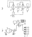
- FIG. 1 shows a feeding system according to the invention in monergol liquid thrusters 1 of an air or space craft such an artificial satellite - in particular a microsatellite or a mini-satellite.
- This system includes a main tank 2 containing a reserve of monergol liquid-in particular hydrazine-pressurized to a pressure Pr, the value of which initial is Po by a neutral gas such as nitrogen fed under pressure in the tank 2.
- the main tank 2 is globally spherical and includes a pressurizing inlet 3 having a pressurizing valve 4 and an orifice 5 input of ergol outlet, diametrically opposed to the inlet 3 of pressurization.
- This secondary reservoir 13 has a fixed volume less than that of the main tank 2.
- the volume of this secondary tank 13 is determined in particular as a function of the flow required by the thrusters 1 and the response time when starting the electric pump 12.
- the volume of the main tank 2 is between 1 l and 100 l
- the tank volume secondary 13 is between 1cm3 and 10cm3.
- the secondary reservoir 13 is connected in parallel to the output 14 of the electropump 12 and is formed of a closed undeformable enclosure enclosing a bellows 15 (or other body deformable) recalled against the pressure in this chamber by 8 return means such as a compression spring, in the direction of a reduction of the useful volume of the secondary reservoir 13.
- these means 8 can be formed of a pressurized neutral gas contained in the bellows 15, as in the main tank 2.
- the secondary reservoir 13 is directly connected with a part at the output 14 of the electric pump 12, and, secondly, to the control valves 16 of each of the thrusters 1.
- a pressure sensor 17 is associated with the secondary reservoir 13 so as to measure the pressure Pa which reign within the secondary tank 13 and which corresponds to the pressure of the liquid that can be supplied to the thrusters 1 by this secondary tank 13.
- the secondary tank 13 thus forms a buffer tank small capacity between the main tank 2 and the thrusters 1, and this tank 13 is maintained pressurized to a predetermined pressure by the electropump 12 and the means of recall, as and when the request for propellant by the thrusters 1.
- a control automation 18 makes it possible to control the operation of the electric pump 12.
- This control automation 18 is adapted to trigger the operation of the electric pump 12 when the pressure Pa measured in the secondary tank 13 becomes less than one predetermined Pamin pressure.
- the automatism 18 is also adapted for interrupt the operation of the electric pump 12 when the pressure Pa measured in the secondary reservoir 13 reaches a predetermined value Pamax, so that thrusters 1 are fed monergol liquid by the tank secondary 13 and / or the electropump 1 under a pressure that remains always included, during the flight of the craft, between Pamin and Pamax.
- the means 8 of are calibrated so that the pressure Pa in the secondary tank 13 can take a value between Pamin and Pamax when the electropump 12 is Operating.
- FIG. 2 shows a simplified flowchart of a feeding method implemented in such a system, by the automation of 18.
- the test step 19 it is examined whether the pressure Pa measured by the sensor 17 is or not lower than the pressure Pamin, which corresponds to the minimum propellant supply pressure 1. If this is the case, the step 20 of igniting the electric pump 12 which delivers to the secondary reservoir 13 a non-zero liquid flow Qs under a given discharge pressure Ps by the means 8 of recall, between Pamin and Pamax according to the rate of filling of the secondary tank 13. Then, in step 21, it is examined whether the pressure Pa supplied by the sensor 17 is or not greater than a value predetermined Pamax corresponding to the maximum pressure that must prevail in the secondary reservoir 13.
- step 19 is performed again. If, during the test step 19, it is found that the pressure Pa prevailing in the secondary reservoir 13 is not inferior to Pamin, this step is permanently closed. Similarly, if, when step 21, we see that the pressure Pa in the secondary reservoir 13 is not greater than Pamax, this test step 21 is continuously closed.
- the electropump 12 is active only when the one or more thrusters 1 requires or has required a liquid flow. It is adapted for able to deliver sufficient liquid flow for the supply of all thrusters 1 connected directly to its output 14 and to the secondary tank 13. When no thruster 1 is active, its discharge pressure Ps is equal, with pressure drops close to the pressure Pa prevailing in the secondary tank 13. This remains true when the thrusters 1 are active to the extent that the flow Qs is greater than the sum of the feed rates of all thrusters.
- the secondary reservoir 13 which is a reservoir of volume pressurized by means 8 recall, has the function of allowing a connection of the volumetric electropump 12 providing a constant flow Qs, thrusters 1 whose flow demand is variable depending on whether one (or several) thruster (s) 1 is (are) active).
- the volume of the secondary reservoir 13 determines the periodicity of triggering of the electric pump 12, depending on the flow rate provided thrusters 1.
- the flow Qs provided by the electric pump 12 must be greater than the sum of the feed rates of the different connected thrusters 1 electropump 12 and the secondary tank 13. In this way, even when all the thrusters 1 are in operation, the electropump 12 will have a intermittent operation, controlled by the control system 18 according to the variations of the pressure Pa within the secondary reservoir 13, between Pamin and Pamax.
- the flow rate Qs provided by the electropump 12 is the same order (slightly higher) than the total feed rate of all thrusters 1.
- the values of Pamin and Pamax are determined for frame the nominal supply pressure Pe thrusters 1 which is in generally between 2 MPa and 2.5 MPa (Pamin ⁇ Pe ⁇ Pamax). For example, for a nominal supply pressure Pe of the order of 2.2 MPa, one chooses Pamin of the order of 2.1 MPa and Pamax of the order of 2.3 MPa.
- the Pamax-Pamin difference represents in the range of 5% to 10% the average value (Pamax + Pamin) / 2, who is herself of the order of Pe.
- a volumetric electropump 12 according to the invention suitable for use in a feeding system according to the invention is described below.
- the electropump 12 comprises a pump body 25 and a electromagnetic actuator with variable reluctance 26 mounted in extension one of the other.
- the pump body 25 comprises a piston 27 guided in translation in a cylinder block 28 along an axis 29 of translation.
- the cylinder block 28 comprises a cylindrical bore 30 and means radial dynamic sealing, for example in the form of an O-ring inserted in a peripheral groove of the piston 27, which seals between the piston 27 and the cylindrical bore 30 over the entire travel of the piston 27.
- the piston 27 has a free end 31 for pumping and the cylindrical bore 30 containing the piston 27 opens, on the side of the free end 31 of the piston 27, in a pumping chamber 32 flared and of at least substantially conical formed in the cylinder block 28.
- This pumping chamber 32 is closed by a flexible metal membrane 33 welded at its periphery to the corresponding wall of the cylinder block 28. This wall is extended axially beyond the membrane 33 so as to form a chamber 34 inlet / outlet which is hermetically closed by a head 35 intake / delivery system incorporating inlet check valves 36 and 37.
- the electric pump comprises preferably two intake inlets 38a, 38b, each connected to a non-return valve intake 36, and receiving the liquid from the main tank 2, and a discharge outlet 39 connected to a discharge check valve 37 delivering the pressurized liquid to the secondary reservoir 13.
- An incompressible neutral liquid for example oil, fills the pumping chamber 32, between the free end 31 of the piston 27 and the flexible membrane 33.
- the flexible membrane 33 thus transmits between the chamber pump 32 and the inlet / outlet chamber 34, the variations of pressure resulting from the alternative translations of the piston 27 into the bore cylindrical 30.
- the end of the cylindrical bore 30 opposite the pumping chamber 32 opens into an isolation chamber 40, of larger radial dimension than the cylindrical bore 30, formed in the cylinder block 28, and closed so sealed at its end opposite the cylindrical bore 30 by a ring 41 axially pierced and a central sleeve 42 pierced with a through bore 43.
- This bore 43 is traversed with a radial clearance by a rod 44 extending the piston 27.
- An elastic bellows 45 surrounds the rod 44 and sealingly connects the central sleeve 42 at the end 46 of the piston 27 which opens into the chamber 40.
- This end 46 is flared so as to have dimensions radial, as well as the bellows 45, very slightly greater than that of the piston 27. In this way, during the reciprocating displacements in translation of the piston 27, the pressure within the isolation chamber 40, filled with oil, remains at least substantially constant.
- This isolation chamber 40 and the static joints 75 between the ring 41 and the sleeve 42 and 77 between the ring 41 and the cylinder block 28 allow to isolate all of the cylindrical bore 30 and the piston 27 external pressure.
- this sealing can be achieved by incorporating the entire actuator 26 in an axial extension of the cylindrical block 28, the assembly being closed hermetically by a cover with a seal static sealing.
- This variant makes the electropump 12 more reliable (replacement of the deformable bellows 45 and seals 76, 77 by a single seal static) and reduce its size and cost.
- Each of the check valves 36, 37 includes a ball 47 biased by a compression spring 48 against a valve seat 49.
- a axial thrust bearing limit stop 50 prevents the axial displacement of the ball 47 beyond its position in which it no longer brakes the flow of liquid passing through the valve seat 49.
- the ball 47 of each valve 36, 37 is advantageously made of silicon nitride and has a diameter of the order of 3mm.
- Such a check valve 36, 37 ball can operate at high frequency, greater than 100 Hz, in particular at a frequency of between 100 Hz and 300 Hz, preferably between 150 Hz and 250 Hz.
- the electromagnetic actuator 26 comprises a body actuator 51 fixed in extension of the cylinder block 28 via a flange 52.
- the head 35 of the cylinder block 28, the cylinder block 28, the flange 52, and the body 51 of the actuator are secured to each other. other two by welding and / or external bolts not represented, in a traditional way.
- the actuator body 51 contains a fixed armature 53 formed of four fixed pieces of magnetic material, each being in the general shape of jumper U or C. These fixed parts are oriented globally radially and regularly distributed at 90 ° to each other around the axis of translation 29.
- each fixed part of the fixed armature 53 has two parallel wings 54, 55 linked by a core 56, and an opening 57 delimited between the free ends of the two wings 54, 55, this opening 57 being oriented opposite the pump body 25, the wings 54, 55 being parallel to the axis of translation 29. All openings 57 and four parts fixed are oriented in the same radial plane.
- the four fixed armatures 53 receive between their wings 54, 55 a magnetization coil 58 centered on the axis of translation 29.
- Each of the fixed pieces 53 is formed of a material magnetic laminated, for example formed of a stack of magnetic sheets, - silicon-thin sheets, isolated from one another and glued to each other.
- Each sheet of this laminated magnetic material is shaped of U or C, and the different U-shaped or C-shaped leaves are superimposed to form a radial stack having the form of jumper.
- Such laminated magnetic material can prevent the development of currents of Foucault when an electric current flows in the coil 58.
- the four fixed pieces 53 are fixed rigidly to the body actuator 51 around a central cylinder 59 of this actuator body 51.
- This central cylinder 59 is hollow and traversed by an axial core 60 rigidly connected to extension of the rod 44 of the piston 27.
- This axial core 60 is fixed at the end of the rod 44, for example by screwing, and opens out opposite the rod 44 axially out of the central cylinder 59 and beyond the fixed armature 53 so as to it can be attached to a cross 61 comprising four radial branches at 90 ° extending opposite the free ends of the wings 54, 55 of the fixed parts 53.
- This cross 61 and the core 60 realize a movable armature 60, 61 guided in translation.
- the axial core 60 and the cross 61 are adapted to define a gap 62 between each of the branches of the cross 61 and the free ends of the wings 54, 55 of the fixed part 53 facing.
- Each of these branches of the cross 61 defines therefore a magnetic circuit with the fixed part 53 opposite, with a gap whose the dimension varies during the translation movements of the mobile armature 60, 61 which is mechanically connected to the piston 27 so as to cause it to translation in the direction corresponding to the phases of liquid discharge during the closure of the air gap induced by the circulation of an electric current in the winding 58, and to be recalled in translation with the piston 27 in the direction corresponding to the liquid intake phases when opening the air gap.
- the cross 61 is made of soft magnetic material massive -notamment soft iron- and present, opposite the air gap 62, longitudinal grooves 69 formed in each of its branches in order to reduce eddy currents. These grooves 69 are hollowed out in the thickness branches, for example by electroerosion.
- the fixed armature 53 can be formed of a piece of soft magnetic material machined in the mass, by example by electroerosion, so as to form two concentric cylinders connected to one of their end by an end ring, receiving between them the magnet winding, and having axial slots in their portions cylindrical and radial in the end ring to achieve a laminating against eddy currents.
- the cross 61 of the movable armature 60, 61 can be replaced by a disk of soft magnetic material machined in the mass, by example by electroerosion, having radial slots producing a lamination against eddy currents.
- the mobile armature 60, 61 thus comprises at least one piece (cross 61 or disc) of magnetic material (soft) extending radially relative to its axis 29 of displacement in translation by relative to the fixed armature 53 to form the gap 62 with this fixed armature 53.
- the electropump 12 comprises means 63 of elastic return of the piston 27 and the movable armature 60, 61 of the actuator electromagnetic field 26, in the direction corresponding to the admission phases of the liquid adapted to be active and provide a booster force when the pressure intake becomes less than a value, called the threshold pressure-especially the order of 0.3MPa-.
- the means 63 for recall are active only in end of stroke of the piston 27 during the delivery phases.
- these means 63 recall are active only in an extreme portion of the stroke of the piston 27.
- the electronic control means are adapted to cause the piston 27 in this extreme portion only when the inlet pressure becomes lower at the threshold pressure.
- the means 63 for recall are inactive as long as the intake pressure remains above the threshold pressure.
- the threshold pressure is greater than the minimum permissible Pmin in the main tank 2.
- the threshold pressure is of the order of 0.3 MPa whereas Pmin is the order of 0.1MPa.
- the return force exerted by the return means 63 is also, during the admission phases, greater or equal to the effort threshold pressure.
- the elastic return means 63 are adapted to provide a recall effort of the order or greater than that corresponding to an intake pressure of the order of 0.3 MPa.
- resilient return means 63 formed of a compression spring 63 interposed between the central sleeve 42 and the end of the axial core 60, this spring 63 being compressed during the delivery phases and relaxing during the phases intake.
- blades 64 radial hoses are associated with the end of the axial core 60 connected to the rod 44, and radial flexible blades 65 are attached to the free end of the axial core 60 connected to the cross 61. These flexible blades 64, 65 also prevent rotation of the movable armature 60, 61 with respect to the actuator body and by relative to the fixed armature 53.
- the piston 27 has a diameter of the order of 5 mm to 10mm -in particular of the order of 6mm- for an axial stroke between 0.5mm and 5mm - especially of the order of 1mm-.
- the gap 62 has a axial dimension slightly greater than the stroke of the piston 27.
- the flexible membrane 33 and the chamber intake / discharge 34 have a diameter of the order of 15mm to 25mm -in particular of the order of 20mm-.
- a sensor 66 of the absolute position of the mobile armature 60, 61 and the piston 27 is associated opposite the free end 71 of the axial core 60.
- This absolute position sensor 66 is fixed to a cross member 75 secured to the body 51.
- a known type sensor 66 may be used. capacitive or eddy currents.
- the electropump 12 furthermore comprises means 70 for power supply and control of the actuator 26 suitable for control operation at an operating frequency greater than 100 Hz - in particular between 100 Hz and 300 Hz, preferably between 150 Hz and 250 Hz-.
- These electronic means 70 comprise an electronic circuit control logic forming the control automation 18, a circuit electronic power 72 controlled by the control automation 18, and receiving electrical energy from a DC voltage source 73 through via filtering means 74.
- the electronic power circuit 72 is connected to the coil 58 which it supplies with electric current.
- the sensor of position 66 provides an electrical signal to the control automation 18 which receives also from the sensor 17 an electrical signal representative of the pressure Pa prevailing in the secondary tank 13.
- the electronic means 70 are adapted to feed the coil 58 pulsed electric current according to the frequency of operation, this current being able to cause the moving armature 60, 61 active in the phases of repression and not to cause the movable armature 60, 61 which is inactive in the intake phases during which the piston 27 and the armature 60, 61 are recalled by the pressure of the liquid on admission, and / or by the means 63 of elastic return.
- the profile of the supply current delivered by the means 70 electronics is also adapted to avoid the contact of the armature mobile 60, 61 with the fixed armature 53 at the end of the discharge phases.
- the electromagnetic actuator 26 includes an end stop 67 cushioned formed of a rubber liner attached to the actuator body 51 facing a collar 68 formed by the end of the axial core 60 connected to the rod 44 of the piston 27.
- the stroke of the movable armature 60, 61 and the piston 27 is limited at the end of the admission phase in any event by the contact between this collar 68 and the abutment 67 secured to the actuator body 51.
- the electronic means 70 can be adapted to deliver a suitable feed stream profile to avoid the contact of the collar 68 of the mobile armature 60, 61 with the stop 67 at the end of the phase intake. Therefore, the electronic means 70 drive the actuator electromagnetic reluctance 26 so that the movable armature 60, 61 moves in alternative axial translations without coming into contact with the fixed armature 53 or the actuator body 51.
- Figure 8 is an example of circuit diagram power electronics 72 formed on the one hand in H of two transistors and diodes.
- This circuit receives a DC supply voltage E and two control H and L delivered by the control automaton 18. These signals of H and L control to control the operation of two switches T1 and T2 formed for example of field effect transistors.
- the coil 58 is connected between the source of transistor T1 and the drain of transistor T2, and the circuit includes two freewheeling diodes D1, D2.
- FIG. 9 represents an electronic diagram of the control automation 18.
- Figure 10 shows an example of chronograrnmes of different signals delivered by the control automat 18 of FIG. 9.
- the control automation 18 develops and supplies the control signals H and L for the transistors of the power circuit 72.
- the control automation 18 is adapted so that the power circuit 72 provides a current profile suitable for the winding 58.
- e of 62 is the maximum air gap
- a large force is required on the piston 27.
- this force is proportional to i 2 / e 2 , where i is the current in the winding 58. It is therefore necessary to provide a strong pulse value of the current.
- the circuit of the control automation 18 of FIG. 9 receives a clock signal CLK which determines the operating frequency and to adjust its value, and a voltage signal VLEM from a sensor of current (for example of Hall effect type) interposed in the circuit, and which is the image of the actual current i flowing in the coil 58. It also provides the H and L control signals applied to the transistors T1 and T2 of the circuit of power 72.
- the clock signal is sent to the inputs of two circuits monostables 81, 82 delivering signals S1 and S2, respectively.
- the first signal S1 makes it possible to set the duration of the slots of a reference signal CONS obtained at the output of an amplification circuit 80 of the signal S1.
- the second signal S2 sets the operating time and forms the control signal L directly applied to transistor T2.
- the setpoint signal CONS determines the duration of the current pulse in the coil 58. It is compared to the VLEM signal, image of the actual current in the winding 58 by a comparison stage 83 to operational amplifier whose output is amplified by a circuit 84.
- the regulation signal REG obtained at the output is supplied by via a diode 85 at the input of an AND gate 86 which also receives the signal S2, whose output delivers the control signal H supplied to the transistor T1 of the power circuit. This produces a regulation of the current i.
- the regulation signal REG is at a high level when CONS ⁇ VLEM.
- the part of the signal H represented in dashed line is that which depends on the actual current i (of which only a theoretical example is shown) in the winding 58.
- the regulation thus carried out makes it possible to obtain a value of the current i in the coil 58 which is at least substantially constant during the impulse, avoiding that it increases too much.
- the filtering means 74 may be made by a conventional differential mode passive filter circuit including a series inductance and parallel capacitance. Such a variant has the advantage simplicity, but the disadvantage of a relatively large size since the value of the components must be relatively high.
- the means of filtering 74 may be formed of an active filter circuit adapted to subtract the current delivered by the voltage source 73, a current whose value is equal contrary to the variations of the current consumed by the power circuit 72, the average value of this consumed current being subtracted.
- FIGS. 9 and 10 correspond to a control automation 18 not including servo means.
- the attractive force between the movable armature 60, 61 and the fixed armature 53 increases, as a first approximation, proportionally to the inverse of the square of the gap.
- the mobile armature 60, 61 arrives in the neighborhood of the fixed armature 53 and is subjected to an extremely large force, which can cause shock. To avoid this inconvenience, it is necessary to cut setpoint winding power supply 58 sufficiently early, and so to cancel the force.
- the electropump 12 may comprise several actuators electromagnetic devices 26, for example mounted head-to-tail on each side of a same pump body 25 so as to form a double-acting pump.
- each pump body can include several parallel pistons so to increase the cubic capacity.
Landscapes
- Engineering & Computer Science (AREA)
- Mechanical Engineering (AREA)
- General Engineering & Computer Science (AREA)
- Chemical & Material Sciences (AREA)
- Combustion & Propulsion (AREA)
- Physics & Mathematics (AREA)
- Fluid Mechanics (AREA)
- Electromagnetic Pumps, Or The Like (AREA)
- Details Of Reciprocating Pumps (AREA)
- Fluid-Pressure Circuits (AREA)
- Jet Pumps And Other Pumps (AREA)
- Filling Or Discharging Of Gas Storage Vessels (AREA)
- Structures Of Non-Positive Displacement Pumps (AREA)
- Cooling, Air Intake And Gas Exhaust, And Fuel Tank Arrangements In Propulsion Units (AREA)
- Output Control And Ontrol Of Special Type Engine (AREA)
- Saccharide Compounds (AREA)
- Valve Device For Special Equipments (AREA)
Description
- au moins un piston guidé en translation dans un bloc cylindre,
- une chambre d'admission/refoulement de liquide dotée de clapets anti-retour d'admission/refoulement et adaptée pour recevoir des variations de pression induites par les déplacements du piston,
- des moyens moteurs électromagnétiques adaptés pour entraíner le piston en translations alternatives dans le bloc cylindre, le déplacement du piston dans un sens correspondant à des phases d'admission du liquide dans la chambre d'admission/refoulement, tandis que le déplacement du piston dans l'autre sens correspond à des phases de refoulement de liquide hors de la chambre d'admission/refoulement,
- au moins un actionneur électromagnétique à réluctance variable unidirectionnel à course linéaire, comprenant une armature mobile associée au piston pour l'entraíner en translation dans le sens correspondant aux phases du refoulement du liquide,
- des moyens électroniques d'alimentation électrique et de commande de l'actionneur adaptés pour en piloter le fonctionnement à une fréquence de fonctionnement supérieure à 100 Hz. Avantageusement et selon l'invention, les moyens électroniques d'alimentation électrique et de commande de l'actionneur sont adaptés pour en piloter le fonctionnement à une fréquence de fonctionnement comprise entre 100 Hz et 300 Hz -notamment entre 150 Hz et 250 Hz-.
- la figure 1 est un schéma d'un système d'alimentation selon l'invention,
- la figure 2 est un organigramme d'un procédé d'alimentation selon l'invention,
- la figure 3 est une coupe axiale schématique d'une électropompe selon l'invention, par un plan diamétral, à l'exception de la tête d'admission/refoulement illustrée en coupe selon deux plans radiaux passant respectivement par l'axe d'un clapet d'admission et l'axe d'un clapet de refoulement, et le support du capteur de position étant illustré en coupe par un plan diamétral différent de celui du corps dé l'électropompe,
- la figure 4 est une vue axiale schématique de dessous selon la ligne IV-IV de la figure 3,
- la figure 5 est une coupe schématique selon la ligne V-V de la figure 3,
- la figure 6 est une vue axiale schématique de dessus selon la ligne VI-VI de la figure 3,
- la figure 7 est un schéma général des moyens électroniques d'alimentation électrique et de commande d'une électropompe selon l'invention,
- la figure 8 est un schéma électronique de la carte de puissance des moyens électroniques d'une électropompe selon l'invention,
- la figure 9 est un schéma électronique d'une carte de commande des moyens électroniques d'une électropompe selon l'invention,
- la figure 10 est un diagramme illustrant des chronogrammes des signaux de la carte de commande de la figure 9,
Claims (14)
- Electropompe volumétrique à déplacement positif linéaire comprenant :caractérisée en ce que les moyens (26, 70) moteurs électromagnétiques comprennent :au moins un piston (27) guidé en translation dans un bloc cylindre (28),une chambre d'admission/refoulement (34) de liquide dotée de clapets (36, 37) anti-retour d'admission/refoulement et adaptée pour recevoir des variations de pression induites par les déplacements du piston (27),des moyens (26, 70) moteurs électromagnétiques adaptés pour entraíner le piston (27) en translations alternatives dans le bloc cylindre (28), le déplacement du piston (27) dans un sens correspondant à des phases d'admission du liquide dans la chambre d'admission/refoulement (34), tandis que le déplacement du piston (27) dans l'autre sens correspond à des phases de refoulement de liquide hors de la chambre d'admission/refoulement (34),au moins un actionneur (26) électromagnétique à réluctance variable unidirectionnel à course linéaire, comprenant une armature mobile (60, 61) associée au piston (27) pour l'entraíner en translation dans le sens correspondant aux phases du refoulement du liquide,des moyens (70) électroniques d'alimentation électrique et de commande de l'actionneur (26) adaptés pour en piloter le fonctionnement à une fréquence de fonctionnement supérieure à 100 Hz.
- Electropompe selon la revendication 1, caractérisée en ce que les moyens (70) électroniques d'alimentation électrique et de commande de l'actionneur (26) sont adaptés pour en piloter le fonctionnement à une fréquence de fonctionnement comprise entre 100 Hz et 300 Hz -notamment entre 150 Hz et 250 Hz-.
- Electropompe selon l'une des revendications 1 ou 2, caractérisée en ce que l'actionneur (26) électromagnétique comprend une armature fixe (53) associée à au moins un bobinage (58) d'aimantation, et une armature mobile (60, 61) guidée en translations alternatives par rapport à l'armature fixe (53) avec laquelle elle définit un circuit magnétique avec un entrefer (62) dont la dimension varie au cours des mouvements de translation de l'armature mobile (60, 61), l'armature mobile (60, 61) étant reliée mécaniquement au piston (27) de façon à l'entraíner en translation dans le sens correspondant aux phases de refoulement du liquide lors de la fermeture de l'entrefer induite par la circulation d'un courant électrique dans le bobinage (58), et à être rappelée en translation avec le piston (27) dans le sens correspondant aux phases d'admission du liquide lors de l'ouverture de l'entrefer (62),
et en ce que lesdits moyens (70) électroniques sont adaptés pour alimenter le bobinage (58) en courant électrique impulsionnel selon la fréquence de fonctionnement apte à entraíner l'armature mobile (60, 61), qui est active, dans les phases de refoulement, et à ne pas entraíner l'armature mobile (60, 61) qui est inactive dans les phases d'admission lors desquelles le piston (27) et l'armature mobile (60, 61), sont rappelés par la pression du liquide à l'admission et/ou par des moyens (63) de rappel élastique. - Electropompe selon la revendication 3, caractérisée en ce que lesdits moyens (70) électroniques sont adaptés pour délivrer un profil de courant d'alimentation adapté pour empêcher le contact de l'armature mobile (60, 61) avec l'armature fixe (53) en fin des phases de refoulement.
- Electropompe selon l'une des revendications 2 à 4, caractérisée en ce que l'actionneur électromagnétique (26) comporte une butée (67) amortie de fin de course limitant l'amplitude de déplacement de l'armature mobile (60, 61) en fin des phases d'admission, et en ce que lesdits moyens (70) électroniques sont adaptés pour délivrer un profil de courant d'alimentation adapté pour empêcher le contact de l'armature mobile (60, 61) avec la butée (67) en fin des phases d'admission.
- Electropompe selon l'une des revendications 2 à 5, caractérisée en ce qu'elle comprend des moyens (63) de rappel élastique du piston (27) et de l'armature mobile (60, 61) de l'actionneur électromagnétique (26), dans le sens correspondant aux phases d'admission du liquide.
- Electropompe selon la revendication 6, caractérisée en ce que les moyens (63) de rappel élastique comprennent un ressort (63) de compression adapté pour être comprimé au moins en fin de phase de refoulement et se détendre au moins en début de phase d'admission.
- Electropompe selon l'une des revendications 6 ou 7, caractérisée en ce que les moyens (63) de rappel élastique sont adaptés pour être actifs et fournir un effort de rappel lorsque la pression d'admission devient inférieure à une valeur, dite pression seuil prédéterminée.
- Electropompe selon l'une des revendications 2 à 8, caractérisée en ce que lesdits moyens (70) électroniques comportent au moins un capteur (66) de la position de l'armature mobile (60, 61) et/ou du piston (27), et des moyens d'asservissement en boucle fermée sur la position de l'armature mobile (60, 61) aptes à adapter le profil du courant électrique d'alimentation de l'actionneur (26) électromagnétique.
- Electropompe selon l'une des revendications 1 à 9,
caractérisée en ce qu'elle comprend des moyens (24) d'étanchéité dynamique entre le piston (27) et le bloc cylindre (28), et une chambre de pompage (32) dans laquelle débouche une extrémité (31) active du piston (27), cette chambre de pompage (53) étant remplie d'un liquide neutre, et séparée de façon étanche de la chambre d'admission/refoulement (34) par une membrane flexible (33) apte à transmettre entre ces deux chambres (32, 34) les variations de pression à la fréquence de fonctionnement, de sorte que le liquide pompé ne vient pas au contact des moyens (24) d'étanchéité dynamique interposés entre le piston (27) et le bloc cylindre (28). - Electropompe selon la revendication 10, caractérisée en ce que la membrane (33) est métallique.
- Electropompe selon l'une des revendications 1 à 11, caractérisée en ce que chacun des clapets (36, 37) anti-retour comprend une bille (47) rappelée par un ressort (48) contre un siège de clapet (49), et une butée (50) axiale de limitation de levée de bille de façon à empêcher le déplacement axial de la bille (47) au-delà de sa position dans laquelle elle ne freine plus l'écoulement traversant le siège du clapet (49).
- Electropompe selon l'une des revendications 1 à 12, caractérisée en ce que chacun des clapets (36, 37) anti-retour comprend une bille (47) en nitrure de silicium dont le diamètre est de l'ordre de 3mm.
- Electropompe selon l'une des revendications 1 à 13, caractérisée en ce que le piston (27) présente un diamètre de 5mm à 10mm -notamment de l'ordre de 6mm- pour une course axiale comprise entre 0,5 mm et 5mm -notamment de l'ordre de 1mm-.
Priority Applications (1)
| Application Number | Priority Date | Filing Date | Title |
|---|---|---|---|
| EP05075714A EP1568877B1 (fr) | 1999-12-21 | 2000-12-19 | Système et procédé d'alimentation d'au moins un propulseur-fusée |
Applications Claiming Priority (3)
| Application Number | Priority Date | Filing Date | Title |
|---|---|---|---|
| FR9916149A FR2802575B1 (fr) | 1999-12-21 | 1999-12-21 | Systeme et procede d'alimentation d'au moins un propulseur, et electropompe a actionneur a reluctance variable haute frequence |
| FR9916149 | 1999-12-21 | ||
| PCT/FR2000/003585 WO2001046581A2 (fr) | 1999-12-21 | 2000-12-19 | Systeme et procede d'alimentation d'au moins un propulseur, et electropompe a actionneur a reluctance variable haute frequence |
Related Child Applications (1)
| Application Number | Title | Priority Date | Filing Date |
|---|---|---|---|
| EP05075714A Division EP1568877B1 (fr) | 1999-12-21 | 2000-12-19 | Système et procédé d'alimentation d'au moins un propulseur-fusée |
Publications (2)
| Publication Number | Publication Date |
|---|---|
| EP1250526A2 EP1250526A2 (fr) | 2002-10-23 |
| EP1250526B1 true EP1250526B1 (fr) | 2005-06-08 |
Family
ID=9553547
Family Applications (2)
| Application Number | Title | Priority Date | Filing Date |
|---|---|---|---|
| EP05075714A Expired - Lifetime EP1568877B1 (fr) | 1999-12-21 | 2000-12-19 | Système et procédé d'alimentation d'au moins un propulseur-fusée |
| EP00988958A Expired - Lifetime EP1250526B1 (fr) | 1999-12-21 | 2000-12-19 | Electropompe a actionneur a reluctance variable haute frequence |
Family Applications Before (1)
| Application Number | Title | Priority Date | Filing Date |
|---|---|---|---|
| EP05075714A Expired - Lifetime EP1568877B1 (fr) | 1999-12-21 | 2000-12-19 | Système et procédé d'alimentation d'au moins un propulseur-fusée |
Country Status (7)
| Country | Link |
|---|---|
| EP (2) | EP1568877B1 (fr) |
| AT (2) | ATE508271T1 (fr) |
| DE (2) | DE60045929D1 (fr) |
| ES (2) | ES2244493T3 (fr) |
| FR (1) | FR2802575B1 (fr) |
| IL (1) | IL150283A (fr) |
| WO (1) | WO2001046581A2 (fr) |
Cited By (1)
| Publication number | Priority date | Publication date | Assignee | Title |
|---|---|---|---|---|
| US12310378B2 (en) | 2020-06-29 | 2025-05-27 | Jbt Marel Corporation | Produce processing dosing system |
Families Citing this family (10)
| Publication number | Priority date | Publication date | Assignee | Title |
|---|---|---|---|---|
| RU2237187C1 (ru) * | 2002-12-17 | 2004-09-27 | Федеральное государственное унитарное предприятие "Центральный институт авиационного моторостроения им. П.И. Баранова" | Система подачи криогенного шугообразного топлива |
| US6892525B2 (en) | 2003-06-06 | 2005-05-17 | Honeywell International Inc. | Micropump-based microthruster |
| FR2916107B1 (fr) | 2007-05-11 | 2015-11-27 | Centre Nat Etd Spatiales | Actionneur alternatif a asservissement en boucle fermee |
| FR2916103B1 (fr) | 2007-05-11 | 2009-06-26 | Cnes Epic | Actionneur electromagnetique a reluctance variable |
| FR2991391B1 (fr) * | 2012-05-30 | 2014-07-04 | Snecma | Dispositif et procede d'alimentation d'une chambre propulsive de moteur-fusee |
| RU2651703C1 (ru) * | 2016-02-12 | 2018-04-23 | Акционерное общество "Информационные спутниковые системы" имени академика М.Ф. Решетнёва" | Блок подачи рабочего тела в реактивный двигатель космического аппарата |
| DE102017120229B4 (de) | 2017-09-03 | 2019-05-09 | Tesat-Spacecom Gmbh & Co.Kg | Regleranordnung mit adaptiver Anpassung der Stellgröße |
| US11155368B1 (en) | 2018-03-13 | 2021-10-26 | Space Systems/Loral, Llc | Multiple thruster firing on a single articulable module |
| US11148833B1 (en) | 2018-05-21 | 2021-10-19 | Space Systems/Loral, Llc | Spacecraft propellant management system |
| CN110821710B (zh) * | 2019-10-28 | 2020-08-21 | 西安航天动力试验技术研究所 | 火箭发动机试验入口压力快速增压装置及液氧供应系统 |
Family Cites Families (4)
| Publication number | Priority date | Publication date | Assignee | Title |
|---|---|---|---|---|
| US3088406A (en) * | 1959-06-22 | 1963-05-07 | Thompson Ramo Wooldridge Inc | Quantized impulse rocket |
| US3769879A (en) * | 1971-12-09 | 1973-11-06 | A Lofquist | Self-compensating diaphragm pump |
| US4696160A (en) * | 1985-05-14 | 1987-09-29 | Trw Inc. | Pressure pump and injector valve system for liquid-propellant engines |
| US5026259A (en) | 1990-07-09 | 1991-06-25 | The United States Of America As Represented By The United States Department Of Energy | Miniaturized pressurization system |
-
1999
- 1999-12-21 FR FR9916149A patent/FR2802575B1/fr not_active Expired - Fee Related
-
2000
- 2000-12-19 ES ES00988958T patent/ES2244493T3/es not_active Expired - Lifetime
- 2000-12-19 ES ES05075714T patent/ES2365787T3/es not_active Expired - Lifetime
- 2000-12-19 AT AT05075714T patent/ATE508271T1/de not_active IP Right Cessation
- 2000-12-19 DE DE60045929T patent/DE60045929D1/de not_active Expired - Lifetime
- 2000-12-19 IL IL15028300A patent/IL150283A/xx not_active IP Right Cessation
- 2000-12-19 AT AT00988958T patent/ATE297501T1/de not_active IP Right Cessation
- 2000-12-19 EP EP05075714A patent/EP1568877B1/fr not_active Expired - Lifetime
- 2000-12-19 WO PCT/FR2000/003585 patent/WO2001046581A2/fr not_active Ceased
- 2000-12-19 EP EP00988958A patent/EP1250526B1/fr not_active Expired - Lifetime
- 2000-12-19 DE DE60020740T patent/DE60020740T2/de not_active Expired - Lifetime
Cited By (1)
| Publication number | Priority date | Publication date | Assignee | Title |
|---|---|---|---|---|
| US12310378B2 (en) | 2020-06-29 | 2025-05-27 | Jbt Marel Corporation | Produce processing dosing system |
Also Published As
| Publication number | Publication date |
|---|---|
| IL150283A0 (en) | 2002-12-01 |
| DE60045929D1 (de) | 2011-06-16 |
| EP1568877A2 (fr) | 2005-08-31 |
| ATE297501T1 (de) | 2005-06-15 |
| DE60020740D1 (de) | 2005-07-14 |
| ATE508271T1 (de) | 2011-05-15 |
| DE60020740T2 (de) | 2006-05-04 |
| WO2001046581A3 (fr) | 2002-01-17 |
| ES2365787T3 (es) | 2011-10-11 |
| EP1568877A3 (fr) | 2007-06-27 |
| ES2244493T3 (es) | 2005-12-16 |
| WO2001046581A2 (fr) | 2001-06-28 |
| FR2802575B1 (fr) | 2002-02-08 |
| IL150283A (en) | 2005-07-25 |
| EP1568877B1 (fr) | 2011-05-04 |
| FR2802575A1 (fr) | 2001-06-22 |
| EP1250526A2 (fr) | 2002-10-23 |
Similar Documents
| Publication | Publication Date | Title |
|---|---|---|
| EP1040274B1 (fr) | Pompe a deplacement positif | |
| CA2073518C (fr) | Vibrateur a moment variable utilisable notamment a l'enfoncement d'objets dans le sol | |
| CA2692703C (fr) | Centrale hydraulique pour moteur a taux de compression variable | |
| WO2001046581A2 (fr) | Systeme et procede d'alimentation d'au moins un propulseur, et electropompe a actionneur a reluctance variable haute frequence | |
| EP4304932B1 (fr) | Dispositif de calage de pas de pales pour turbomachine et turbomachine le comportant | |
| EP0047209A1 (fr) | Amortisseur | |
| FR2560644A1 (fr) | Soupape d'injection electromagnetique | |
| FR2467439A1 (fr) | Systeme et procede de regulation de pression d'un fluide | |
| FR2768215A1 (fr) | Systeme de lubrification d'un mecanisme, notamment d'un palier tournant dans un engin spatial | |
| EP0511055A1 (fr) | Barre élastique de liaison à système de contrôle actif des vibrations | |
| EP3071825B1 (fr) | Dispositif d'alimentation en ergol de chambre propulsive de moteur-fusée | |
| EP0454545A1 (fr) | Dispositif d'assemblage mécanique temporaire et de séparation rapide d'un objet à éjecter lié à un support | |
| EP1132581B1 (fr) | Soupape à commande électromagnétique, à ressort pneumatique et articulation par genouillère | |
| CA2687069A1 (fr) | Actionneur alternatif a asservissement en boucle fermee | |
| WO2023031572A1 (fr) | Actionneur électromagnétique à entrainement direct et amortissement amélioré | |
| WO2024068634A1 (fr) | Electrovanne et equipement avec l'electrovanne | |
| FR2941745A3 (fr) | Dispositif d'injection de liquide, notamment de carburant. | |
| EP1044329A1 (fr) | Pompe actionnee par un transducteur electrodynamique et procede de fabrication d'une telle pompe | |
| FR2914024A1 (fr) | Injecteur de carburant pour moteur a combustion interne | |
| WO1994010522A1 (fr) | Amortissement du piston d'un canon a charge propulsive liquide | |
| EP2391815A1 (fr) | Dispositif d'injection de liquide, notamment de carburant, avec un actionneur electroactif | |
| EP1342913B1 (fr) | Injecteur de carburant | |
| EP0737275A1 (fr) | Dispositif de transmission d'energie de commande mecanique | |
| FR3006071A1 (fr) | Procede de regulation d'un actionneur electropneumatique |
Legal Events
| Date | Code | Title | Description |
|---|---|---|---|
| PUAI | Public reference made under article 153(3) epc to a published international application that has entered the european phase |
Free format text: ORIGINAL CODE: 0009012 |
|
| 17P | Request for examination filed |
Effective date: 20020716 |
|
| AK | Designated contracting states |
Kind code of ref document: A2 Designated state(s): AT BE CH CY DE DK ES FI GB GR IE IT LI LU MC NL PT SE TR |
|
| 17Q | First examination report despatched |
Effective date: 20040609 |
|
| GRAP | Despatch of communication of intention to grant a patent |
Free format text: ORIGINAL CODE: EPIDOSNIGR1 |
|
| RTI1 | Title (correction) |
Free format text: ELECTRICALLY-DRIVEN FEED PUMP WITH HIGH FREQUENCY VARIABLE RELUCTANCE ACTUATOR |
|
| GRAS | Grant fee paid |
Free format text: ORIGINAL CODE: EPIDOSNIGR3 |
|
| GRAA | (expected) grant |
Free format text: ORIGINAL CODE: 0009210 |
|
| AK | Designated contracting states |
Kind code of ref document: B1 Designated state(s): AT BE CH CY DE DK ES FI GB GR IE IT LI LU MC NL PT SE TR |
|
| PG25 | Lapsed in a contracting state [announced via postgrant information from national office to epo] |
Ref country code: TR Free format text: LAPSE BECAUSE OF FAILURE TO SUBMIT A TRANSLATION OF THE DESCRIPTION OR TO PAY THE FEE WITHIN THE PRESCRIBED TIME-LIMIT Effective date: 20050608 Ref country code: NL Free format text: LAPSE BECAUSE OF FAILURE TO SUBMIT A TRANSLATION OF THE DESCRIPTION OR TO PAY THE FEE WITHIN THE PRESCRIBED TIME-LIMIT Effective date: 20050608 Ref country code: IE Free format text: LAPSE BECAUSE OF FAILURE TO SUBMIT A TRANSLATION OF THE DESCRIPTION OR TO PAY THE FEE WITHIN THE PRESCRIBED TIME-LIMIT Effective date: 20050608 Ref country code: AT Free format text: LAPSE BECAUSE OF FAILURE TO SUBMIT A TRANSLATION OF THE DESCRIPTION OR TO PAY THE FEE WITHIN THE PRESCRIBED TIME-LIMIT Effective date: 20050608 Ref country code: FI Free format text: LAPSE BECAUSE OF FAILURE TO SUBMIT A TRANSLATION OF THE DESCRIPTION OR TO PAY THE FEE WITHIN THE PRESCRIBED TIME-LIMIT Effective date: 20050608 |
|
| REG | Reference to a national code |
Ref country code: GB Ref legal event code: FG4D Free format text: NOT ENGLISH |
|
| REG | Reference to a national code |
Ref country code: CH Ref legal event code: EP |
|
| REF | Corresponds to: |
Ref document number: 60020740 Country of ref document: DE Date of ref document: 20050714 Kind code of ref document: P |
|
| REG | Reference to a national code |
Ref country code: IE Ref legal event code: FG4D Free format text: LANGUAGE OF EP DOCUMENT: FRENCH |
|
| PG25 | Lapsed in a contracting state [announced via postgrant information from national office to epo] |
Ref country code: DK Free format text: LAPSE BECAUSE OF FAILURE TO SUBMIT A TRANSLATION OF THE DESCRIPTION OR TO PAY THE FEE WITHIN THE PRESCRIBED TIME-LIMIT Effective date: 20050908 Ref country code: SE Free format text: LAPSE BECAUSE OF FAILURE TO SUBMIT A TRANSLATION OF THE DESCRIPTION OR TO PAY THE FEE WITHIN THE PRESCRIBED TIME-LIMIT Effective date: 20050908 Ref country code: GR Free format text: LAPSE BECAUSE OF FAILURE TO SUBMIT A TRANSLATION OF THE DESCRIPTION OR TO PAY THE FEE WITHIN THE PRESCRIBED TIME-LIMIT Effective date: 20050908 |
|
| GBT | Gb: translation of ep patent filed (gb section 77(6)(a)/1977) |
Effective date: 20050921 |
|
| PG25 | Lapsed in a contracting state [announced via postgrant information from national office to epo] |
Ref country code: PT Free format text: LAPSE BECAUSE OF FAILURE TO SUBMIT A TRANSLATION OF THE DESCRIPTION OR TO PAY THE FEE WITHIN THE PRESCRIBED TIME-LIMIT Effective date: 20051114 |
|
| NLV1 | Nl: lapsed or annulled due to failure to fulfill the requirements of art. 29p and 29m of the patents act | ||
| REG | Reference to a national code |
Ref country code: ES Ref legal event code: FG2A Ref document number: 2244493 Country of ref document: ES Kind code of ref document: T3 |
|
| PG25 | Lapsed in a contracting state [announced via postgrant information from national office to epo] |
Ref country code: CY Free format text: LAPSE BECAUSE OF FAILURE TO SUBMIT A TRANSLATION OF THE DESCRIPTION OR TO PAY THE FEE WITHIN THE PRESCRIBED TIME-LIMIT Effective date: 20051219 |
|
| PG25 | Lapsed in a contracting state [announced via postgrant information from national office to epo] |
Ref country code: LI Free format text: LAPSE BECAUSE OF NON-PAYMENT OF DUE FEES Effective date: 20051231 Ref country code: MC Free format text: LAPSE BECAUSE OF NON-PAYMENT OF DUE FEES Effective date: 20051231 Ref country code: CH Free format text: LAPSE BECAUSE OF NON-PAYMENT OF DUE FEES Effective date: 20051231 Ref country code: LU Free format text: LAPSE BECAUSE OF NON-PAYMENT OF DUE FEES Effective date: 20051231 |
|
| REG | Reference to a national code |
Ref country code: IE Ref legal event code: FD4D |
|
| PLBE | No opposition filed within time limit |
Free format text: ORIGINAL CODE: 0009261 |
|
| STAA | Information on the status of an ep patent application or granted ep patent |
Free format text: STATUS: NO OPPOSITION FILED WITHIN TIME LIMIT |
|
| 26N | No opposition filed |
Effective date: 20060309 |
|
| REG | Reference to a national code |
Ref country code: CH Ref legal event code: PL |
|
| PGFP | Annual fee paid to national office [announced via postgrant information from national office to epo] |
Ref country code: DE Payment date: 20121207 Year of fee payment: 13 |
|
| PGFP | Annual fee paid to national office [announced via postgrant information from national office to epo] |
Ref country code: IT Payment date: 20121214 Year of fee payment: 13 Ref country code: ES Payment date: 20121219 Year of fee payment: 13 Ref country code: GB Payment date: 20121219 Year of fee payment: 13 |
|
| PGFP | Annual fee paid to national office [announced via postgrant information from national office to epo] |
Ref country code: BE Payment date: 20121219 Year of fee payment: 13 |
|
| BERE | Be: lapsed |
Owner name: CENTRE NATIONAL D'ETUDES *SPATIALES Effective date: 20131231 |
|
| REG | Reference to a national code |
Ref country code: DE Ref legal event code: R119 Ref document number: 60020740 Country of ref document: DE |
|
| GBPC | Gb: european patent ceased through non-payment of renewal fee |
Effective date: 20131219 |
|
| REG | Reference to a national code |
Ref country code: DE Ref legal event code: R119 Ref document number: 60020740 Country of ref document: DE Effective date: 20140701 |
|
| PG25 | Lapsed in a contracting state [announced via postgrant information from national office to epo] |
Ref country code: BE Free format text: LAPSE BECAUSE OF NON-PAYMENT OF DUE FEES Effective date: 20131231 Ref country code: DE Free format text: LAPSE BECAUSE OF NON-PAYMENT OF DUE FEES Effective date: 20140701 |
|
| PG25 | Lapsed in a contracting state [announced via postgrant information from national office to epo] |
Ref country code: GB Free format text: LAPSE BECAUSE OF NON-PAYMENT OF DUE FEES Effective date: 20131219 |
|
| REG | Reference to a national code |
Ref country code: ES Ref legal event code: FD2A Effective date: 20150504 |
|
| PG25 | Lapsed in a contracting state [announced via postgrant information from national office to epo] |
Ref country code: ES Free format text: LAPSE BECAUSE OF NON-PAYMENT OF DUE FEES Effective date: 20131220 |
|
| PG25 | Lapsed in a contracting state [announced via postgrant information from national office to epo] |
Ref country code: IT Free format text: LAPSE BECAUSE OF NON-PAYMENT OF DUE FEES Effective date: 20131231 |
|
| PG25 | Lapsed in a contracting state [announced via postgrant information from national office to epo] |
Ref country code: IT Free format text: LAPSE BECAUSE OF NON-PAYMENT OF DUE FEES Effective date: 20131219 |