EP1249993A1 - Call forwarding (diversion) with retrieval function on diversion to voice mail - Google Patents
Call forwarding (diversion) with retrieval function on diversion to voice mail Download PDFInfo
- Publication number
- EP1249993A1 EP1249993A1 EP20010303388 EP01303388A EP1249993A1 EP 1249993 A1 EP1249993 A1 EP 1249993A1 EP 20010303388 EP20010303388 EP 20010303388 EP 01303388 A EP01303388 A EP 01303388A EP 1249993 A1 EP1249993 A1 EP 1249993A1
- Authority
- EP
- European Patent Office
- Prior art keywords
- communication unit
- data communication
- communication
- communication system
- link
- Prior art date
- Legal status (The legal status is an assumption and is not a legal conclusion. Google has not performed a legal analysis and makes no representation as to the accuracy of the status listed.)
- Withdrawn
Links
- 238000010586 diagram Methods 0.000 description 5
Images

Classifications
-
- H—ELECTRICITY
- H04—ELECTRIC COMMUNICATION TECHNIQUE
- H04M—TELEPHONIC COMMUNICATION
- H04M3/00—Automatic or semi-automatic exchanges
- H04M3/20—Automatic or semi-automatic exchanges with means for interrupting existing connections; with means for breaking-in on conversations
-
- H—ELECTRICITY
- H04—ELECTRIC COMMUNICATION TECHNIQUE
- H04M—TELEPHONIC COMMUNICATION
- H04M3/00—Automatic or semi-automatic exchanges
- H04M3/42—Systems providing special services or facilities to subscribers
- H04M3/50—Centralised arrangements for answering calls; Centralised arrangements for recording messages for absent or busy subscribers ; Centralised arrangements for recording messages
- H04M3/53—Centralised arrangements for recording incoming messages, i.e. mailbox systems
- H04M3/533—Voice mail systems
-
- H—ELECTRICITY
- H04—ELECTRIC COMMUNICATION TECHNIQUE
- H04M—TELEPHONIC COMMUNICATION
- H04M3/00—Automatic or semi-automatic exchanges
- H04M3/42—Systems providing special services or facilities to subscribers
- H04M3/54—Arrangements for diverting calls for one subscriber to another predetermined subscriber
Definitions
- the invention relates to a data communication system comprising a multiple of communication units and at least one telephone exchange for establishing at least a first communication link between a first communication unit of the communication system and a second communication unit of the communication system upon initialisation of the first communication unit, wherein the data communication system is further arranged for automatically transferring the first communication link into a transferred communication link between the first communication unit and a third communication unit of the communication system when the data communication system is in a transfer-mode with respect to the second communication unit.
- the invention also relates to a telephone exchange for establishing at least a first communication link between a first communication unit and a second communication unit upon initialisation of the first communication unit, wherein the telephone exchange is further arranged for automatically transferring the first communication link into a transferred communication link between the first communication unit and a third communication unit when the telephone exchange is in a transfer-mode with respect to the second communication unit.
- a first user can give a call via the first communication unit to the second communication unit of a second user.
- the data communication system establishes the first communication link between the first communication unit and the second communication unit upon initialisation of the first communication unit. Then, if the data communication unit is in the transfer-mode with respect to the second communication unit the first communication link is automatically transferred into the third communication unit of a third user upon initialisation of the first communication unit. For this the transferred communication link is established between the first communication unit and the third communication unit.
- a disadvantage of the known data communication system and the known telephone exchange is that the second user loses control over the transferred communication link. For example, it is impossible for the second user to retrieve the transferred communication link.
- An embodiment of the data communication system according to the invention is characterised in that the data communication system is further arranged for transmitting a notification-signal to the second communication unit when the first communication link is transferred into the transferred communication link.
- the notification signal can draw the attention of the second user that a communication link which has been directed to the second communication unit is transferred automatically to the third user.
- the notification-signal can be a Ping-ring signal or an ISDN notification-signal. Subsequently the second user can retrieve the transferred communication link via the at least one telephone exchange.
- An advanced embodiment of the data communication system of the invention is characterised in that the data communication system comprises a wireless mobile data communication network comprising at least one of said communication units.
- the data communication system can also comprise a conventional fixed data communication network comprising at least one of said communication units.
- the telephone exchange according to the invention is characterised in that the telephone exchange is arranged such that the second communication unit can re-establish the first communication link from the transferred communication link.
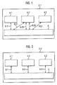
- FIG. 1 is a schematic diagram of a data communication system 2.1.
- the data communication system 2.1 comprises a multiple of communication units 4.1, 4.2, 4.3. Each communication unit can be used by one or more users.
- the first communication unit is used by a first user, the second communication system by a second user and the third communication unit by a third user.
- the data communication system 2.1 also comprises a telephone exchange 6 for establishing at least a first communication link 8.1, 8.21 between the first communication unit 4.1 and the second communication unit 4.2.
- the first communication link 8.1, 8.21 is established upon initialisation of the first communication unit 4.1. This initialisation is performed by the first user which calls the second user by entering the identification code of the second communication unit 4.2 into the first communication unit 4.1.
- the data communication system 2.1 is in a transfer-mode with respect to the second communication unit 4.2 (in this example data communication system 2.1 can be put in said transfer-mode upon reception by telephone exchange 6 of a switch-to-transfer-mode signal from the second communication system 2.1), the first communication link 8.1, 8.21 is automatically transferred into a transferred communication link 8.1, 8.21, 8.22, 8.3 between the first communication unit 4.1 and the third communication unit 4.3.
- the transferred data communication link still comprises sublinks with communication unit 4.2. (As will be explained later it is equally possible that a transferred link resulting from the first communication link does not comprise a sublink with the second communication unit 4.2).
- the second user of the second communication unit 4.2 can re-establish the first communication link 8.1, 8.21 from the transferred data communication link 8.1, 8.21, 8.22, 8.3 via the second communication unit 4.2.
- a first example of re-establishing the first communication link is a situation wherein the sublink 8.22 is just disconnected upon a control message "retrieve communication link" which has been sent by the second communication unit 4.2 to the telephone exchange 6.
- the second user transmits a control message "retrieve communication link" to the telephone exchange 6 via the sublink 8.21, the sublink 8.22 or a separate link 8.23.
- the telephone exchange 6 can re-establisch the first communication link 8.1, 8.21.
- the data communication system 2.1 is arranged for transmitting a notification-signal to the second communication unit 4.2 when the first communication link 8.1, 8.21 is transferred.
- the notification signal is transmitted by the telephone exchange 6 to the second communication unit 4.2 via one of the (sub)links 8.21, 8.22 or 8.23.
- the second user of the second communication unit 4.2 will be informed via the notification signal that a communication link will be automatically, or already is, transferred from the second communication unit to the third communication unit. This offers the second user the possibility to re-establish the (already) transferred communication link.
- the notification-signal can be a Ping-ring signal.
- the notification signal can be an ISDN notification signal.
- the third data communication unit 4.3 is a Voice Mail Box. So, when a first user calls the second data communication unit 4.2 via the first communication link 8.1, 8.21 and the second user does not reply the call, then subsequently the first data communication link 8.1, 8.21 is transferred to the Voice Mail Box. This is also called Call diversion on no reply. Next, if the second user was to late to answer the call, the second user can retrieve the first data communication link (and thus the call) in the manner which has been explained hereinbefore. In this case it is not necessary that a notification signal is transmitted to the second data communication unit 4.2 since the second user has already been notified about the transfer via the call via the first communication link.
- the data communication system 2.1 and more in particular the telephone exchange 6, can be switched to a transfer-mode upon reception of a switch-to-transfer-mode signal, which signal can be transmitted by the second user from the second data communication unit 4.2.
- a switch-to-transfer-mode signal which signal can be transmitted by the second user from the second data communication unit 4.2.
- the switch-to-transfer-mode signal comprises transfer-mode-information relating to the second communication unit 4.2 and the third communication unit 4.3.
- the transfer-mode-information is stored in memory means of the data communication system 2.1.
- the data communication system 2.1 Upon reception of a switch-to-normal-mode signal, which signal can be transmitted by the second user from the second data communication unit 4.2, the data communication system 2.1 switches from transfer-mode to a normal-mode with respect to the second communication unit 4.2. Hereby the transfer-mode-information in said memory means is erased and communication links which are established to the second data communication unit 4.2 are no longer transferred to the third data communication unit 4.3.
- FIG. 2 schematically shows a second data communication system 2.2. It is noted that corresponding parts in the figures 1 and 2 are referred to with corresponding numbers. Furthermore the data communication system 2.2 mainly operates in the same manner as the data communication system 2.1. If the data communication system 2.2 is in a transfer-mode with respect to the second data communication unit 4.2 then the first data communication link 8.1, 8.2 is transferred into a transferred data communication link 8.1, 8.3 to the third data communication unit. In this case the transferred communication link does not comprise a sublink with the second communication unit 4.2. This means that the first data communication link is "directly" transferred (this is also called “immediate diversion").
- a notification signal can be transmitted from the telephone exchange 6 to the second data communication system 4.2 to inform the second user of the second data communication system 4.2 that a transfer has taken place. Subsequently the second user can re-establish the first communication link, for example by transmitting a "retrieve communication link" command to the telephone exchange 6.
- FIG. 3 schematically shows a third data communication system 2.3. It is noted that corresponding parts in the figures 1 and 3 are referred to with corresponding numbers.
- the data communication system 2.3 operates in a similar way as the data communication system 2.1. However, contrary to the systems 2.1 and 2.2 the data communication system 2.3 comprises two telephone exchanges 6.1 and 6.2.
- the first data communication unit 4.1 communicates via data communication link 8.1 with the first telephone exchange 6.1.
- the first telephone exchange 6.1 communicates to the second data communication unit 4.2 via the data link 8.21.
- the second telephone exchange 6.2 communicates with the second data communication unit 4.2 via the data link 8.22 and with the third data communication unit 4.3 via the data link 8.3.
- the telephone exchange 6.1 and/or the telephone exchange 6.2 can comprise memory means for storing transfer-mode-information).
- Figure 4 schematically shows a fourth data communication system 2.4. It is noted that corresponding parts in the figures 1 and 4 are referred to with corresponding numbers.
- a first data communication link 8.1, 8.12, 8.2 between the first data communication unit 4.1 and the second data communication unit 4.2 is established by the first telephone exchanges 6.1 and 6.2.
- the sublink 8.12 is established by the first telephone exchange 6.1.
- the data communication system 2.4 is in a transfer mode with respect to the data communication unit 4.2, the first data communication link 8.1, 8.12, 8.2 is transferred into the transferred data communication link 8.1, 8.12, 8.23, 8.3 to the third communication unit 4.3 via the three telephone exchanges 6.1, 6.2 and 6.3.
- the transferred data communication link does not comprise a sublink with the second data communication unit 4.2 (direct transfer). Therefore, if the second user of the second data communication unit 4.2 wants to retrieve the transferred data communication link 8.1, 8.12, 8.23, 8.3 a new data communication link between the unit 4.2 and the telephone exchange 6.2 has to be established for transmitting a "retrieve communication link" command to the telephone exchange 6.2. Next, the second telephone exchange 6.2 can re-establish the first data communication link from the transferred data communication link.
- the data communication system can comprise a wireless mobile data communication network comprising at least one of said communication units and/or a fixed data communication network comprising at least one of said communication units.
- the telephone exchange(s) in the data communicating system can be analog and/or digital exchanges or a combination thereof.
- the data communication system can comprise a digital highway for internet applications, wherein the data communication links are used for transferring digital data packages to internet addresses.
Landscapes
- Engineering & Computer Science (AREA)
- Signal Processing (AREA)
- Mobile Radio Communication Systems (AREA)
- Telephonic Communication Services (AREA)
Abstract
The system has a multiple of communication units and a telephone exchange for establishing a communication link between a communication unit of the communication system and a second communication unit of the communication system upon initialization of the first communication unit. The data communication system automatically transfers the first communication link into a transferred communication link between the first communication unit and a third communication unit of the communication system when the data communication system is in a transfer-mode with respect to the second communication unit. The data communication system is arranged so that the second communication unit can re-establish the first communication link from the transferred communication link. An independent claim is included for a telephone exchange.
Description
- The invention relates to a data communication system comprising a multiple of communication units and at least one telephone exchange for establishing at least a first communication link between a first communication unit of the communication system and a second communication unit of the communication system upon initialisation of the first communication unit, wherein the data communication system is further arranged for automatically transferring the first communication link into a transferred communication link between the first communication unit and a third communication unit of the communication system when the data communication system is in a transfer-mode with respect to the second communication unit.
- The invention also relates to a telephone exchange for establishing at least a first communication link between a first communication unit and a second communication unit upon initialisation of the first communication unit, wherein the telephone exchange is further arranged for automatically transferring the first communication link into a transferred communication link between the first communication unit and a third communication unit when the telephone exchange is in a transfer-mode with respect to the second communication unit.
- The above mentioned data communication system and the above mentioned telephone exchange are known in actual practice. Herewith a first user can give a call via the first communication unit to the second communication unit of a second user. In this case the data communication system establishes the first communication link between the first communication unit and the second communication unit upon initialisation of the first communication unit. Then, if the data communication unit is in the transfer-mode with respect to the second communication unit the first communication link is automatically transferred into the third communication unit of a third user upon initialisation of the first communication unit. For this the transferred communication link is established between the first communication unit and the third communication unit.
- A disadvantage of the known data communication system and the known telephone exchange is that the second user loses control over the transferred communication link. For example, it is impossible for the second user to retrieve the transferred communication link.
- It is an object of the invention to meet said disadvantage of the known data communication system. This is achieved with the data communication system of the invention which is characterised in that the data communication system is arranged such that the second communication unit can re-establish the first communication link from the transferred data communication link. In this way the second user can retrieve the transferred communication link.
- An embodiment of the data communication system according to the invention is characterised in that the data communication system is further arranged for transmitting a notification-signal to the second communication unit when the first communication link is transferred into the transferred communication link. The notification signal can draw the attention of the second user that a communication link which has been directed to the second communication unit is transferred automatically to the third user. The notification-signal can be a Ping-ring signal or an ISDN notification-signal. Subsequently the second user can retrieve the transferred communication link via the at least one telephone exchange.
- An advanced embodiment of the data communication system of the invention is characterised in that the data communication system comprises a wireless mobile data communication network comprising at least one of said communication units. The data communication system can also comprise a conventional fixed data communication network comprising at least one of said communication units.
- The telephone exchange according to the invention is characterised in that the telephone exchange is arranged such that the second communication unit can re-establish the first communication link from the transferred communication link.
- In the accompanying drawings, in which several modes of carrying out the present invention are shown for illustrative purposes:
- Figure 1 is a diagram schematically showing a first data communication system according to the invention.
- Figure 2 is a diagram schematically showing a second data communication system according to the invention.
- Figure 3 is a diagram schematically showing a third data communication system according to the invention which comprises two telephone exchanges.
- Figure 4 is a diagram schematically showing a fourth data communication system according to the invention which comprises three telephone exchanges.
-
- Figure 1 is a schematic diagram of a data communication system 2.1. The data communication system 2.1 comprises a multiple of communication units 4.1, 4.2, 4.3. Each communication unit can be used by one or more users. In this example the first communication unit is used by a first user, the second communication system by a second user and the third communication unit by a third user. The data communication system 2.1 also comprises a
telephone exchange 6 for establishing at least a first communication link 8.1, 8.21 between the first communication unit 4.1 and the second communication unit 4.2. The first communication link 8.1, 8.21 is established upon initialisation of the first communication unit 4.1. This initialisation is performed by the first user which calls the second user by entering the identification code of the second communication unit 4.2 into the first communication unit 4.1. - Then, if the data communication system 2.1 is in a transfer-mode with respect to the second communication unit 4.2 (in this example data communication system 2.1 can be put in said transfer-mode upon reception by
telephone exchange 6 of a switch-to-transfer-mode signal from the second communication system 2.1), the first communication link 8.1, 8.21 is automatically transferred into a transferred communication link 8.1, 8.21, 8.22, 8.3 between the first communication unit 4.1 and the third communication unit 4.3. In this example the transferred data communication link still comprises sublinks with communication unit 4.2. (As will be explained later it is equally possible that a transferred link resulting from the first communication link does not comprise a sublink with the second communication unit 4.2). After this the second user of the second communication unit 4.2 can re-establish the first communication link 8.1, 8.21 from the transferred data communication link 8.1, 8.21, 8.22, 8.3 via the second communication unit 4.2. A first example of re-establishing the first communication link is a situation wherein the sublink 8.22 is just disconnected upon a control message "retrieve communication link" which has been sent by the second communication unit 4.2 to thetelephone exchange 6. In a second example the second user transmits a control message "retrieve communication link" to thetelephone exchange 6 via the sublink 8.21, the sublink 8.22 or a separate link 8.23. Subsequently, thetelephone exchange 6 can re-establisch the first communication link 8.1, 8.21. - The data communication system 2.1 is arranged for transmitting a notification-signal to the second communication unit 4.2 when the first communication link 8.1, 8.21 is transferred. In this example the notification signal is transmitted by the
telephone exchange 6 to the second communication unit 4.2 via one of the (sub)links 8.21, 8.22 or 8.23. The second user of the second communication unit 4.2 will be informed via the notification signal that a communication link will be automatically, or already is, transferred from the second communication unit to the third communication unit. This offers the second user the possibility to re-establish the (already) transferred communication link. In a particular example of an analog telephone exchange the notification-signal can be a Ping-ring signal. In a particular example of a digital telephone exchange the notification signal can be an ISDN notification signal. - In this example the third data communication unit 4.3 is a Voice Mail Box. So, when a first user calls the second data communication unit 4.2 via the first communication link 8.1, 8.21 and the second user does not reply the call, then subsequently the first data communication link 8.1, 8.21 is transferred to the Voice Mail Box. This is also called Call diversion on no reply. Next, if the second user was to late to answer the call, the second user can retrieve the first data communication link (and thus the call) in the manner which has been explained hereinbefore. In this case it is not necessary that a notification signal is transmitted to the second data communication unit 4.2 since the second user has already been notified about the transfer via the call via the first communication link.
- The data communication system 2.1, and more in particular the
telephone exchange 6, can be switched to a transfer-mode upon reception of a switch-to-transfer-mode signal, which signal can be transmitted by the second user from the second data communication unit 4.2. When the data communication system 2.1 is in the transfer-mode with respect to the second data communication unit 4.2 all communication links which are directed to the second data communication unit 4.2 will automatically be transferred into the transferred data communication link 8.1, 8.21, 8.22, 8.3. - The switch-to-transfer-mode signal comprises transfer-mode-information relating to the second communication unit 4.2 and the third communication unit 4.3. The transfer-mode-information is stored in memory means of the data communication system 2.1.
- Upon reception of a switch-to-normal-mode signal, which signal can be transmitted by the second user from the second data communication unit 4.2, the data communication system 2.1 switches from transfer-mode to a normal-mode with respect to the second communication unit 4.2. Hereby the transfer-mode-information in said memory means is erased and communication links which are established to the second data communication unit 4.2 are no longer transferred to the third data communication unit 4.3.
- Figure 2 schematically shows a second data communication system 2.2. It is noted that corresponding parts in the figures 1 and 2 are referred to with corresponding numbers. Furthermore the data communication system 2.2 mainly operates in the same manner as the data communication system 2.1. If the data communication system 2.2 is in a transfer-mode with respect to the second data communication unit 4.2 then the first data communication link 8.1, 8.2 is transferred into a transferred data communication link 8.1, 8.3 to the third data communication unit. In this case the transferred communication link does not comprise a sublink with the second communication unit 4.2. This means that the first data communication link is "directly" transferred (this is also called "immediate diversion"). Eventually a notification signal can be transmitted from the
telephone exchange 6 to the second data communication system 4.2 to inform the second user of the second data communication system 4.2 that a transfer has taken place. Subsequently the second user can re-establish the first communication link, for example by transmitting a "retrieve communication link" command to thetelephone exchange 6. - Figure 3 schematically shows a third data communication system 2.3. It is noted that corresponding parts in the figures 1 and 3 are referred to with corresponding numbers. The data communication system 2.3 operates in a similar way as the data communication system 2.1. However, contrary to the systems 2.1 and 2.2 the data communication system 2.3 comprises two telephone exchanges 6.1 and 6.2. Herewith the first data communication unit 4.1 communicates via data communication link 8.1 with the first telephone exchange 6.1. Furthermore the first telephone exchange 6.1 communicates to the second data communication unit 4.2 via the data link 8.21. The second telephone exchange 6.2 communicates with the second data communication unit 4.2 via the data link 8.22 and with the third data communication unit 4.3 via the data link 8.3. (The telephone exchange 6.1 and/or the telephone exchange 6.2 can comprise memory means for storing transfer-mode-information).
- Figure 4 schematically shows a fourth data communication system 2.4. It is noted that corresponding parts in the figures 1 and 4 are referred to with corresponding numbers. Upon initialisation of the first data communication unit 4.1 a first data communication link 8.1, 8.12, 8.2 between the first data communication unit 4.1 and the second data communication unit 4.2 is established by the first telephone exchanges 6.1 and 6.2. The sublink 8.12 is established by the first telephone exchange 6.1. Then, if the data communication system 2.4 is in a transfer mode with respect to the data communication unit 4.2, the first data communication link 8.1, 8.12, 8.2 is transferred into the transferred data communication link 8.1, 8.12, 8.23, 8.3 to the third communication unit 4.3 via the three telephone exchanges 6.1, 6.2 and 6.3. Note that the transferred data communication link does not comprise a sublink with the second data communication unit 4.2 (direct transfer). Therefore, if the second user of the second data communication unit 4.2 wants to retrieve the transferred data communication link 8.1, 8.12, 8.23, 8.3 a new data communication link between the unit 4.2 and the telephone exchange 6.2 has to be established for transmitting a "retrieve communication link" command to the telephone exchange 6.2. Next, the second telephone exchange 6.2 can re-establish the first data communication link from the transferred data communication link.
- It is noted that the data communication system can comprise a wireless mobile data communication network comprising at least one of said communication units and/or a fixed data communication network comprising at least one of said communication units.
- The present invention has been described in what is considered to represent its preferred embodiments. However, it should be noted that the invention can be practised otherwise than as specifically illustrated and described without departing from its spirit or scope. For example, the telephone exchange(s) in the data communicating system can be analog and/or digital exchanges or a combination thereof. Furthermore the data communication system can comprise a digital highway for internet applications, wherein the data communication links are used for transferring digital data packages to internet addresses.
Claims (9)
- Data communication system comprising a multiple of communication units and at least one telephone exchange for establishing at least a first communication link between a first communication unit of the communication system and a second communication unit of the communication system upon initialisation of the first communication unit, wherein the data communication system is further arranged for automatically transferring the first communication link into a transferred communication link between the first communication unit and a third communication unit of the communication system when the data communication system is in a transfer-mode with respect to the second communication unit,
characterised in that,
the data communication system is arranged such that the second communication unit can re-establish the first communication link from the transferred communication link. - Data communication system according claim 1,
characterised in that,
the data communication system is further arranged for transmitting a notification-signal to the second communication unit when the first communication link is transferred into the transferred communication link. - Data communication system according to claim 2,
characterised in that,
the notification-signal is a Ping-ring signal to be transmitted by the at least one telephone exchange. - Data communication system according to claim 2,
characterised in that,
the notification-signal is an ISDN notification signal to be transmitted by the at least one telephone exchange. - Data communication system according to one of the preceding claims,
characterised in that,
the data communication system is arranged for switching to said transfer-mode upon reception of a switch-to-transfer-mode signal from the second data communication unit, wherein the switch-to-transfer-mode signal comprises transfer-mode-information relating to the second communication unit and the third communication unit, and wherein the data communication system comprises memory means for storing said transfer-mode-information. - Data communication system according to claim 5,
characterised in that,
the data communication system is arranged for switching from said transfer-mode to a normal-mode with respect to the second communication unit and for erasing said transfer-mode-information in said memory means upon reception of a switch-to-normal-mode signal from the second communication unit. - Data communication system according to one of the preceding claims,
characterised in that,
the data communication system comprises a wireless mobile data communication network comprising at least one of said communication units. - Data communication system according to one of the preceding claims,
characterised in that,
the data communication system comprises a conventional fixed data communication network comprising at least one of said communication units. - Telephone exchange for establishing at least a first communication link between a first communication unit and a second communication unit upon initialisation of the first communication unit, wherein the telephone exchange is further arranged for automatically transferring the first communication link into a transferred communication link between the first communication unit and a third communication unit when the telephone exchange is in a transfer-mode with respect to the second communication unit,
characterised in that,
the telephone exchange is arranged such that the second communication unit can re-establish the first communication link from the transferred communication link.
Priority Applications (1)
| Application Number | Priority Date | Filing Date | Title |
|---|---|---|---|
| EP20010303388 EP1249993A1 (en) | 2001-04-11 | 2001-04-11 | Call forwarding (diversion) with retrieval function on diversion to voice mail |
Applications Claiming Priority (1)
| Application Number | Priority Date | Filing Date | Title |
|---|---|---|---|
| EP20010303388 EP1249993A1 (en) | 2001-04-11 | 2001-04-11 | Call forwarding (diversion) with retrieval function on diversion to voice mail |
Publications (1)
| Publication Number | Publication Date |
|---|---|
| EP1249993A1 true EP1249993A1 (en) | 2002-10-16 |
Family
ID=8181893
Family Applications (1)
| Application Number | Title | Priority Date | Filing Date |
|---|---|---|---|
| EP20010303388 Withdrawn EP1249993A1 (en) | 2001-04-11 | 2001-04-11 | Call forwarding (diversion) with retrieval function on diversion to voice mail |
Country Status (1)
| Country | Link |
|---|---|
| EP (1) | EP1249993A1 (en) |
Cited By (2)
| Publication number | Priority date | Publication date | Assignee | Title |
|---|---|---|---|---|
| EP2043347A1 (en) * | 2007-09-26 | 2009-04-01 | Alcatel Lucent | Method of providing an improved call forwarding service |
| GB2491602A (en) * | 2011-06-07 | 2012-12-12 | Metaswitch Networks Ltd | Processing media data for a multi service user and a method for alerting a multi service user |
Citations (3)
| Publication number | Priority date | Publication date | Assignee | Title |
|---|---|---|---|---|
| EP0689333A2 (en) * | 1994-06-23 | 1995-12-27 | AT&T Corp. | Personal mobile communication system |
| US5668853A (en) * | 1992-09-10 | 1997-09-16 | Northern Telecom Limited | Telecommunications calling feature method and apparatus |
| WO2000039990A1 (en) * | 1998-12-23 | 2000-07-06 | Ericsson Inc. | Voice mail intervention |
-
2001
- 2001-04-11 EP EP20010303388 patent/EP1249993A1/en not_active Withdrawn
Patent Citations (3)
| Publication number | Priority date | Publication date | Assignee | Title |
|---|---|---|---|---|
| US5668853A (en) * | 1992-09-10 | 1997-09-16 | Northern Telecom Limited | Telecommunications calling feature method and apparatus |
| EP0689333A2 (en) * | 1994-06-23 | 1995-12-27 | AT&T Corp. | Personal mobile communication system |
| WO2000039990A1 (en) * | 1998-12-23 | 2000-07-06 | Ericsson Inc. | Voice mail intervention |
Cited By (4)
| Publication number | Priority date | Publication date | Assignee | Title |
|---|---|---|---|---|
| EP2043347A1 (en) * | 2007-09-26 | 2009-04-01 | Alcatel Lucent | Method of providing an improved call forwarding service |
| GB2491602A (en) * | 2011-06-07 | 2012-12-12 | Metaswitch Networks Ltd | Processing media data for a multi service user and a method for alerting a multi service user |
| US9729713B2 (en) | 2011-06-07 | 2017-08-08 | Metaswitch Networks Ltd | Method and system for processing media data for later access |
| GB2491602B (en) * | 2011-06-07 | 2018-02-07 | Metaswitch Networks Ltd | Data Processing |
Similar Documents
| Publication | Publication Date | Title |
|---|---|---|
| JP3108217B2 (en) | How to replace mobile phone with fixed-line telephone set | |
| JPS62115991A (en) | Cell type mobile telephone communication system | |
| AU4746500A (en) | Processing of calls terminating in a packet switched protocol based cellular communication network | |
| US4885769A (en) | Station controller for enhanced multi-line pick-up in centrex exchange telephone system | |
| US8121592B2 (en) | Mobile communication system and communication holding method | |
| US6192234B1 (en) | Automatic call coverage administration by wireless terminals | |
| US5200996A (en) | Station controller for multi-line pick-up and automatic monitoring of telephone station moves | |
| US6101396A (en) | Dynamic call coverage paths based on auxiliary units | |
| JP3276912B2 (en) | Transparency of wireless handset features between switching nodes | |
| CA2107982C (en) | Connection control method for personal communications | |
| EP1223773B1 (en) | Mobile communication service control system and mobile communication service control method | |
| KR20010011750A (en) | Method for providing call forwarding service in the moble communication system | |
| US7127263B1 (en) | Private branch exchange system | |
| JP2683795B2 (en) | Communication channel switching method | |
| AU781860B2 (en) | Radio communication system, private branch exchange and radio terminal for place of business | |
| US5884183A (en) | Mobile communication system and message output method therefor | |
| KR100239175B1 (en) | How to Send Incoming Information from a Phone to a Registered Terminal | |
| JPH02260996A (en) | Isdn terminal adapter | |
| KR20030018470A (en) | The method of auto dialing for exchange between mobile phone and general telephone | |
| JPH1169458A (en) | Signaling area determination method for paging incoming calls | |
| JPH09149458A (en) | Mobile phone and mail system having the same | |
| JPH03280768A (en) | Ic card telephone system | |
| JPH0965006A (en) | ISDN terminal device | |
| JPS63204928A (en) | Connecting method for call of mobile communication | |
| JPH0230265A (en) | Inter-station relay call transfer system |
Legal Events
| Date | Code | Title | Description |
|---|---|---|---|
| PUAI | Public reference made under article 153(3) epc to a published international application that has entered the european phase |
Free format text: ORIGINAL CODE: 0009012 |
|
| AK | Designated contracting states |
Kind code of ref document: A1 Designated state(s): AT BE CH CY DE DK ES FI FR GB GR IE IT LI LU MC NL PT SE TR |
|
| AX | Request for extension of the european patent |
Free format text: AL;LT;LV;MK;RO;SI |
|
| AKX | Designation fees paid | ||
| REG | Reference to a national code |
Ref country code: DE Ref legal event code: 8566 |
|
| STAA | Information on the status of an ep patent application or granted ep patent |
Free format text: STATUS: THE APPLICATION IS DEEMED TO BE WITHDRAWN |
|
| 18D | Application deemed to be withdrawn |
Effective date: 20030417 |