EP1249968A2 - Cable modem apparatus and frequency setting method applied thereto - Google Patents
Cable modem apparatus and frequency setting method applied thereto Download PDFInfo
- Publication number
- EP1249968A2 EP1249968A2 EP02001924A EP02001924A EP1249968A2 EP 1249968 A2 EP1249968 A2 EP 1249968A2 EP 02001924 A EP02001924 A EP 02001924A EP 02001924 A EP02001924 A EP 02001924A EP 1249968 A2 EP1249968 A2 EP 1249968A2
- Authority
- EP
- European Patent Office
- Prior art keywords
- frequency
- data
- frequency data
- matching
- cache area
- Prior art date
- Legal status (The legal status is an assumption and is not a legal conclusion. Google has not performed a legal analysis and makes no representation as to the accuracy of the status listed.)
- Withdrawn
Links
Images


Classifications
-
- H—ELECTRICITY
- H04—ELECTRIC COMMUNICATION TECHNIQUE
- H04N—PICTORIAL COMMUNICATION, e.g. TELEVISION
- H04N21/00—Selective content distribution, e.g. interactive television or video on demand [VOD]
- H04N21/40—Client devices specifically adapted for the reception of or interaction with content, e.g. set-top-box [STB]; Operations thereof
- H04N21/41—Structure of client; Structure of client peripherals
- H04N21/426—Internal components of the client ; Characteristics thereof
- H04N21/42676—Internal components of the client ; Characteristics thereof for modulating an analogue carrier signal to encode digital information or demodulating it to decode digital information, e.g. ADSL or cable modem
-
- H—ELECTRICITY
- H04—ELECTRIC COMMUNICATION TECHNIQUE
- H04N—PICTORIAL COMMUNICATION, e.g. TELEVISION
- H04N21/00—Selective content distribution, e.g. interactive television or video on demand [VOD]
- H04N21/40—Client devices specifically adapted for the reception of or interaction with content, e.g. set-top-box [STB]; Operations thereof
- H04N21/43—Processing of content or additional data, e.g. demultiplexing additional data from a digital video stream; Elementary client operations, e.g. monitoring of home network or synchronising decoder's clock; Client middleware
- H04N21/433—Content storage operation, e.g. storage operation in response to a pause request, caching operations
- H04N21/4331—Caching operations, e.g. of an advertisement for later insertion during playback
-
- H—ELECTRICITY
- H04—ELECTRIC COMMUNICATION TECHNIQUE
- H04N—PICTORIAL COMMUNICATION, e.g. TELEVISION
- H04N21/00—Selective content distribution, e.g. interactive television or video on demand [VOD]
- H04N21/40—Client devices specifically adapted for the reception of or interaction with content, e.g. set-top-box [STB]; Operations thereof
- H04N21/45—Management operations performed by the client for facilitating the reception of or the interaction with the content or administrating data related to the end-user or to the client device itself, e.g. learning user preferences for recommending movies, resolving scheduling conflicts
- H04N21/462—Content or additional data management e.g. creating a master electronic programme guide from data received from the Internet and a Head-end or controlling the complexity of a video stream by scaling the resolution or bit-rate based on the client capabilities
- H04N21/4622—Retrieving content or additional data from different sources, e.g. from a broadcast channel and the Internet
-
- H—ELECTRICITY
- H04—ELECTRIC COMMUNICATION TECHNIQUE
- H04N—PICTORIAL COMMUNICATION, e.g. TELEVISION
- H04N21/00—Selective content distribution, e.g. interactive television or video on demand [VOD]
- H04N21/40—Client devices specifically adapted for the reception of or interaction with content, e.g. set-top-box [STB]; Operations thereof
- H04N21/47—End-user applications
- H04N21/478—Supplemental services, e.g. displaying phone caller identification, shopping application
- H04N21/4782—Web browsing, e.g. WebTV
-
- H—ELECTRICITY
- H04—ELECTRIC COMMUNICATION TECHNIQUE
- H04N—PICTORIAL COMMUNICATION, e.g. TELEVISION
- H04N21/00—Selective content distribution, e.g. interactive television or video on demand [VOD]
- H04N21/60—Network structure or processes for video distribution between server and client or between remote clients; Control signalling between clients, server and network components; Transmission of management data between server and client, e.g. sending from server to client commands for recording incoming content stream; Communication details between server and client
- H04N21/61—Network physical structure; Signal processing
- H04N21/6106—Network physical structure; Signal processing specially adapted to the downstream path of the transmission network
- H04N21/6118—Network physical structure; Signal processing specially adapted to the downstream path of the transmission network involving cable transmission, e.g. using a cable modem
-
- H—ELECTRICITY
- H04—ELECTRIC COMMUNICATION TECHNIQUE
- H04N—PICTORIAL COMMUNICATION, e.g. TELEVISION
- H04N21/00—Selective content distribution, e.g. interactive television or video on demand [VOD]
- H04N21/60—Network structure or processes for video distribution between server and client or between remote clients; Control signalling between clients, server and network components; Transmission of management data between server and client, e.g. sending from server to client commands for recording incoming content stream; Communication details between server and client
- H04N21/61—Network physical structure; Signal processing
- H04N21/6156—Network physical structure; Signal processing specially adapted to the upstream path of the transmission network
- H04N21/6168—Network physical structure; Signal processing specially adapted to the upstream path of the transmission network involving cable transmission, e.g. using a cable modem
-
- H—ELECTRICITY
- H04—ELECTRIC COMMUNICATION TECHNIQUE
- H04N—PICTORIAL COMMUNICATION, e.g. TELEVISION
- H04N7/00—Television systems
- H04N7/16—Analogue secrecy systems; Analogue subscription systems
- H04N7/173—Analogue secrecy systems; Analogue subscription systems with two-way working, e.g. subscriber sending a programme selection signal
- H04N7/17309—Transmission or handling of upstream communications
Definitions
- the present invention relates to a cable modem apparatus for realizing connection to the Internet using, for example, a CATV system.
- connection schemes access schemes for the Internet have increased by using not only typical telephone lines but also satellite communication channels, CATV (Cable Television) systems (CATV stations and associated facilities) or the like.
- CATV Internet a scheme employing a CATV system (CATV Internet) draws attention as a promising one since it can realize an environment for the Internet capable of continuous connection at high speed.
- the CATV Internet is configured such that a CATV (center station) is connected to users through cables (coaxial cables) and the CATV is connected to the Internet.
- a user accesses the Internet through the CATV station which also serves as an ISP (Internet Service Provider).
- ISP Internet Service Provider
- a general configuration for realizing the CATV Internet includes a kind of relay apparatus (having functions of a bridge and a router) called a CMTS (Cable Modem Termination System) or a head end modem (HM) on the CATV station side connected to a cable modem (CM) provided on the user side through a cable.
- the cable modem is connected to a personal computer (PC) and the like operated by a user.
- PC personal computer
- TV television set
- the TV is typically connected to the CM in parallel through a distributor.
- a communication channel between the CMTS on the CATV station side and the CM on the user side comprises a downlink for transmission to the user side and an uplink in the reverse direction.
- the downlink mainly for downloading homepages from the Internet (such as processing with a WWW browser) and the like has a higher transmission speed than the uplink.
- Frequency bands used are, for example, a range of 90 to 857 MHz for the downlink and a range of 10 to 55 MHz for the uplink.
- the cable modem (CM) for realizing the above-mentioned CATV Internet has an interface function for transmission and reception of data to and from the Internet through the CMTS on the CATV station side and the cable.
- the CM since the CM receives information transmitted from the CMTS at power-on through the downlink for which conditions of communication between the CM and the CMTS are specified, such as the condition of which channel (data transmission frequency) of the uplink is used to transmit data to the CMTS or the condition of which symbol rate (modulation rate) is used therefor, the CM has the function of tuning (selecting a matching frequency) in to a channel (data transmission frequency) of the downlink on which the information is transmitted thereto.
- a conventional CM has a plurality of preset frequency data as a table (frequency table) stored therein such that it selects available (matching) frequency data following entries in the frequency table at power-on.
- the CM sets the selected frequency data in an RF (Radio Frequency) interface and determines whether that frequency is matching (whether it can tune in to a data transmission frequency) within several seconds. If the selected frequency data is not matching, the CM selects frequency data in the next entry in the frequency table and sets it in the RF interface.
- the CM repeats processing of selecting and setting frequency data in turn from the frequency table until it can tune in to a data transmission frequency for the downlink.
- the present invention is applied to a system for constructing the CATV Internet, and particularly, relates to a cable modem apparatus capable of performing processing of tuning in to a data transmission frequency in a downlink in a short time.
- the cable modem apparatus comprises interface means configured to transmit and receive a data signal transported through a cable based on set frequency data, memory means for storing a frequency table for selecting a frequency matching the frequency of the data signal transmitted through the cable and having a cache area for saving frequency data which has been selected previously from the frequency table, setting means for selecting matching frequency data from the cache area or the frequency table in the memory at start of communication to set the selected frequency data in the interface, and means for saving information indicative of frequency data in the cache area when the frequency data selected from the frequency table is matching.
- frequency data saved in the cache area is selected with priority before frequency data are searched from all the entries in the frequency table. Since the frequency data saved in the cache area has been previously selected, it is likely to be matching frequency data. Therefore, matching frequency data can be selected in a short time, and consequently, tuning processing for a data transmission frequency in the downlink can be performed in a short time. It is thus possible to perform efficiently processing of preparing communication with the Internet.
- FIG. 1 is a block diagram showing the configuration of a system for constructing the CATV Internet according to the embodiment
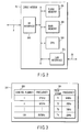
- FIG. 2 is a block diagram showing main portions of a cable modem (CM) according to the embodiment
- FIG. 3 is a table illustrating an example of contents stored in a flash memory (memory means) according to the embodiment.
- CM cable modem
- a system 1 on the side of a CATV station is connected to systems 2 on the side of users through a coaxial cable (or called an RF cable and hereinafter referred to simply as "cable") 3.
- a coaxial cable or called an RF cable and hereinafter referred to simply as "cable" 3.
- the system 1 of the CATV station comprises a CMTS 10, a server 12, and a router 13, all of which are connected to a LAN cable 11.
- the server 12 implements the function of an ISP (Internet Service Provider) for managing data communication between the Internet 30 connected thereto through the LAN cable 11 and the router 13, and the users 2 connected through the CMTS 10.
- the CMTS 10 is a kind of relay apparatus (having the functions of a bridge and a router) also called a head end modem (HM) as described above.
- Each system 2 on the user side comprises a cable modem (CM) 20 connected to the CMTS 10 on the CATV station side through the cable 3, and a personal computer (PC) 21 connected to the CM 20 through a home LAN cable (hereinafter referred to simply as "LAN cable").
- CM cable modem
- PC personal computer
- LAN cable home LAN cable
- a distributor for distributing signals to the CM 20 and a television set (TV) connected to the cable 3 for receiving CATV broadcasts.
- the CM 20 of the embodiment comprises an RF interface 200, a flash memory 201, a main memory 202, a microprocessor (CPU) 203, and a LAN interface 204.
- RF interface 200 As shown in FIG. 2, the CM 20 of the embodiment comprises an RF interface 200, a flash memory 201, a main memory 202, a microprocessor (CPU) 203, and a LAN interface 204.
- CPU microprocessor
- the RF interface 200 has the function of transmitting and receiving data signals (analog signals) through the cable 3, the A/D converting function of converting the received data signals into digital signals, and the D/A converting function of converting data signals to be transmitted into analog signals.
- the RF interface 200 has a variety of parameters set therein in accordance with frequency data selected by the CPU 203, later described, and performs processing of tuning (processing for extracting a data signal with a frequency matching the data signal) in to a data transmission frequency in a downlink.
- the flash memory 201 stores a frequency table 300 as shown in FIG. 3 and has a cache area 301 as well as a program required for the operation of the CPU 203.
- the main memory 202 is accessed by the CPU 203 and holds a variety of data for use during the operation of the CM 20.
- the CPU 203 is a controller of the CM 20 for controlling the processing of tuning in to the data transmission frequency in the downlink related to the embodiment (later described).
- the LAN interface 204 is an interface connecting the CM 20 with the PC 21 through a LAN cable 22.
- the system 2 on the user side is continuously connected to the system 1 on the CATV station side through the cable 3.
- the CM 20 starts the processing of tuning in to the data transmission frequency in the downlink as communication preparation processing for communicating with the Internet 30.
- the CPU 203 accesses the cache area 301 of the flash memory 201 to check whether previously used frequency data is saved therein (steps S1, S2). If such data is not saved in the cache area 301, the CPU 203 searches frequency data corresponding to the first entry from the frequency table 300 stored in the flash memory 201 (step S9).
- the frequency table 300 includes channel numbers and frequency data for each entry and has been previously set in a fixed manner.
- the cache memory 301 is an area, as later described, for saving frequency data selected as matching frequency data, and has a capacity which can store data of items 1 to 4 including time stamp information (T1 to T4) added thereto.
- the CPU 203 stores the frequency data read out from the cache area 301 of the flash memory 201 or the frequency table 300 into the main memory 202 (step S3).
- the frequency data read out from the frequency table 300 is stored in the main memory 202.
- the CPU 203 sets parameters corresponding to the frequency data stored in the main memory 202 in the RF interface 200 (step S4).
- the RF interface 200 performs the tuning processing for the data transmission frequency in the downlink for transmission through the cable 3 in a predetermined time (several seconds) in accordance with the parameters corresponding to the set frequency data (step S5).
- the CPU 203 determines whether a data signal can be captured with the data transmission frequency based on a notification from the RF interface 200 (step S6).
- the CPU 203 reads out frequency data in the next entry from the frequency table 300 and saves the read data into the main memory 202 (No at step S6, steps S7 and S3).
- frequency data (94 MHz) of a channel number 2 is selected, for example, and saved in the main memory 202.
- the RF interface 200 performs the tuning processing for the data transmission frequency with the selected frequency data.
- the CPU 203 determines that the frequency data (94 MHz) selected from the flash memory 201 is matching and saves the data in the cache area 301 (YES at step S6 and step S8). The CPU 203 then starts, for example, an examination of a frequency in the uplink as next processing.
- the frequency data is set as frequency data that matches the communication with the Internet.
- the CPU 203 saves the selected frequency data (for example, 94 MHz) as a matching frequency into the cache area 301 of the flash memory 201.
- frequency data used is saved in the cache area 301.
- the cache area 301 may save up to four frequency data such that the latest frequency data can be selected therefrom with time stamp information (T1 to T4).
- the cache area 301 may be updated each time a selection is made therefrom to have only the latest frequency data saved therein all the time.
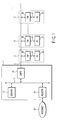
- FIG. 5 is a flow chart related to a modification of the embodiment.
- the modification is a scheme in which, when frequency data are selected in turn from all the entries in the frequency table 300, frequency data saved in the cache area 301 is used at predetermined intervals (the number N of readouts) to perform tuning processing.
- the CPU 203 accesses the cache area 301 of the flash memory 201 to check whether or not previously used frequency data is saved therein (steps S20, S21). If such data is not saved in the cache area 301, the CPU 203 searches frequency data corresponding to the first entry from the frequency table 300 stored in the flash memory 201 (step S31).
- an entry pointer for the frequency table is set to zero at step S22 and the procedure proceeds to step S23.
- the CPU 203 stores the frequency data read out from the cache area 301 of the flash memory 201 or the frequency table 300 into the main memory 202 (step S23).
- the frequency data read out from the cache area 301 is stored in the main memory 202.
- the CPU 203 sets parameters corresponding to the frequency data stored in the main memory 202 in the RF interface 200 (step S24).
- the RF interface 200 performs processing of tuning in to a data transmission frequency in the downlink for transmission through the cable 3 in a predetermined time (several seconds) in accordance with the parameters corresponding to the set frequency data (step S25).
- the CPU 203 determines whether a data signal can be caught (extracted) with the data transmission frequency based on a notification from the RF interface 200 (step S26).
- the CPU 203 reads frequency data in the next entry from the frequency table 300 and stores the read data into the main memory 202 (step S27). While the CPU 203 reads frequency data in turn from all the entries in the frequency table until catching is successfully made, the CPU 203 searches frequency data from the cache area 301 every predetermined "N" number of readouts and continues the tuning processing (step S28).
- the CPU 203 determines that the frequency data selected from the flash memory 201 is matching and saves the data into the cache area 301 (step S30). The CPU 203 then starts, for example, an examination of a frequency in the uplink as next processing.
- the frequency data saved in the cache area 301 is again used while the processing is continued following the entries in the frequency table 300. If the effect of noise is eliminated, the frequency data saved in the cache area 301 is likely to be matching. Therefore, since it is possible to select frequency data which is likely to be matching from the cache area 301 while the frequency data are selected in turn from all the entries in the frequency table 300, matching frequency data can be consequently set in a short time.
- the cable modem apparatus of the present invention is applied, for example, to a system for constructing the CATV Internet, thereby making it possible to realize a system capable of completing processing for preparing communication with the Internet in a short time.
- FIG. 6 is a flow chart related to another modification of the embodiment.
- the modification is a scheme in which, when frequency data are selected in turn from all the entries in the cache area 301, frequency data saved in the frequency table 300 is used at predetermined intervals (the number N of readouts) to perform tuning processing.
- the CPU 203 sets zero in an entry pointer K in the cache area 301.
- the CPU 203 determines whether or not a predetermined interval has elapsed (number N of readouts is reached). If the predetermined interval has not elapsed, the CPU 203 searches frequency data from entries in the cache area 301 at step S45.
- the CPU 203 determines whether or not a data signal can be caught (extracted) from the searched data transmission frequency.
- the CPU 203 increments the entry pointer K in the cache area 301 by one at step S49, and the procedure proceeds to steps S43, S45 to search frequency data in the next entry.
- the CPU 203 starts, for example, an examination of a frequency in the uplink as next processing.
- the CPU reads frequency data out from entries in the frequency table 300 at step S51. Then, at step S53, when the data signal is not caught successfully with the read frequency data, the CPU 203 returns to the step S41. On the other had, if the catching succeeds, the CPU 203 starts, for example, an examination of a frequency in the uplink as next processing.
Landscapes
- Engineering & Computer Science (AREA)
- Multimedia (AREA)
- Signal Processing (AREA)
- Databases & Information Systems (AREA)
- Two-Way Televisions, Distribution Of Moving Picture Or The Like (AREA)
- Communication Control (AREA)
Abstract
Description
Claims (8)
- A cable modem apparatus connected to a network (30) system (30) through a cable (3), characterized by comprising:an interface (200) configured to transmit and receive a data signal transported through said cable based on set frequency data;a memory (201) configured to store a frequency table (300) for selecting a frequency matching the frequency of said data signal transmitted through said cable and having a cache area (301) for saving frequency data which has been selected previously from said frequency table;setting means (203) configured to select matching frequency data from said cache area or said frequency table in said memory at start of communication to set said selected frequency data in said interface; andsaving means (203) configured to save information indicative of frequency data in said cache area when said frequency data selected from said frequency table is matching.
- The cable modem apparatus according to claim 1, characterized in that said setting means (203) selects frequency data with priority in accordance with the information saved in said cache area (301), and when it is determined that said frequency data is not matching, said setting means sequentially searches said frequency table (300) for matching frequency data.
- The cable modem apparatus according to claim 1, characterized in that said setting means (203) selects frequency data with priority in accordance with the information saved in said cache area (3d), and when it is determined that said frequency data is not matching, said setting means sequentially searches said frequency data for matching frequency data and determines at predetermined intervals whether or not frequency data in accordance with the information saved in said cache area (301) is matching.
- The cable modem apparatus according to claim 1, characterized in that said setting means (203) sequentially searches said cache area (301) for matching frequency data and determines at predetermined intervals whether said frequency data stored in said frequency table (300) is matching.
- A method of setting a frequency applied to a cable modem apparatus (20) connected to a network system (30) through a cable (3), said cable modem apparatus comprising an interface (200) configured to transmit and receive a data signal based on set frequency data, and a memory (201) configured to store a frequency table (300) for selecting a frequency matching the frequency of said data signal transmitted through said cable and having a cache area (301) for saving frequency data which has been selected previously from said frequency table, said method comprising the steps of:selecting (S1-S3) frequency data with priority from said cache area of said memory at start of communication;sequentially selecting frequency (S3-S7) data from said frequency table to find matching frequency data when said frequency data selected from said cache area is not matching; andselecting (54) matching frequency data from said cache area or said frequency table to set said selected data in said interface.
- The method according to claim 5, characterized in that frequency data is selected with priority in accordance with the information saved in said cache area, and when it is determined that said frequency data is not matching, said frequency table is sequentially searched for matching frequency data and determination is made at predetermined intervals whether frequency data saved in said cache area is matching (ND in step S6,S7,S3).
- The method according to claim 5, characterized in that said cache area is sequentially searched for matching frequency data and determination is made at predetermined intervals whether or not frequency data stored in said frequency table is matching (FIG. 6).
- A method of setting a frequency applied to a cable modem apparatus (20) connected to a network system (30) through a cable (3), said cable modem apparatus comprising an interface (200) configured to transmit and receive a data signal based on set frequency data, and a memory (201) configured to store a frequency table for selecting a frequency matching the frequency of said data signal transmitted through said cable and having a cache area for saving frequency data which has been selected previously from said frequency table, said method comprising the steps of:searching (FIG. 5) said cache area of said memory at start of communication, and when frequency data is stored in said cache area, setting said frequency data stored in said cache area in said interface, and when no frequency data is stored in said cache area, setting matching frequency data from said frequency table in said interface; andwhen a data signal is successfully captured in said interface, saving said frequency data in said cache area (FIG. 5).
Applications Claiming Priority (2)
| Application Number | Priority Date | Filing Date | Title |
|---|---|---|---|
| JP2001054947A JP2002261863A (en) | 2001-02-28 | 2001-02-28 | Cable modem device and frequency setting method applied to the device |
| JP2001054947 | 2001-02-28 |
Publications (2)
| Publication Number | Publication Date |
|---|---|
| EP1249968A2 true EP1249968A2 (en) | 2002-10-16 |
| EP1249968A3 EP1249968A3 (en) | 2003-07-23 |
Family
ID=18915207
Family Applications (1)
| Application Number | Title | Priority Date | Filing Date |
|---|---|---|---|
| EP02001924A Withdrawn EP1249968A3 (en) | 2001-02-28 | 2002-01-31 | Cable modem apparatus and frequency setting method applied thereto |
Country Status (3)
| Country | Link |
|---|---|
| US (1) | US20020120941A1 (en) |
| EP (1) | EP1249968A3 (en) |
| JP (1) | JP2002261863A (en) |
Families Citing this family (2)
| Publication number | Priority date | Publication date | Assignee | Title |
|---|---|---|---|---|
| WO2012139299A1 (en) * | 2011-04-15 | 2012-10-18 | Nokia Siemens Networks Oy | Nodeb self-tuning |
| CN108965860B (en) * | 2018-06-05 | 2020-04-07 | 深圳市共进电子股份有限公司 | Anti-interference test system, method and device for cable modem downlink signal |
Family Cites Families (17)
| Publication number | Priority date | Publication date | Assignee | Title |
|---|---|---|---|---|
| US5751772A (en) * | 1996-02-28 | 1998-05-12 | Motorola, Inc. | Method for locating a channel in a communication system |
| US5983115A (en) * | 1996-08-13 | 1999-11-09 | Lucent Technologies Inc. | Geographic based method for selecting a wireless communications service provider |
| US6081533A (en) * | 1997-06-25 | 2000-06-27 | Com21, Inc. | Method and apparatus for an application interface module in a subscriber terminal unit |
| US6941120B2 (en) * | 1997-07-29 | 2005-09-06 | Gray Electronics, Inc. | Apparatus and method for automatically programming frequency scanning radio receivers |
| US5937351A (en) * | 1997-10-24 | 1999-08-10 | Motorola, Inc. | Method for establishing a wireless communications link in a reduced time |
| US6421728B1 (en) * | 1997-12-31 | 2002-07-16 | Intel Corporation | Architecture for communicating with and controlling separate upstream and downstream devices |
| US6343070B1 (en) * | 1998-06-08 | 2002-01-29 | Ericcson Inc. | Methods for reducing channel acquisition times in a radiotelephone communications system and related mobile terminals |
| US6230326B1 (en) * | 1998-07-30 | 2001-05-08 | Nortel Networks Limited | Method and apparatus for initialization of a cable modem |
| US6574796B1 (en) * | 1999-01-08 | 2003-06-03 | Cisco Technology, Inc. | Fast and reliable data carrier detection by a cable modem in a cable television plant |
| US6148203A (en) * | 1999-03-08 | 2000-11-14 | Motorola, Inc. | Method for registering a communication device for communication service |
| US6742186B1 (en) * | 1999-06-02 | 2004-05-25 | Cisco Technology, Inc. | Method and apparatus for enhancing periodic ranging for cable modems |
| US6453472B1 (en) * | 1999-06-02 | 2002-09-17 | Cisco Technology, Inc. | Method and apparatus for performing periodic ranging for cable modems |
| US6877166B1 (en) * | 2000-01-18 | 2005-04-05 | Cisco Technology, Inc. | Intelligent power level adjustment for cable modems in presence of noise |
| WO2001056188A1 (en) * | 2000-01-26 | 2001-08-02 | Vyyo, Ltd. | Offset carrier frequency correction in a two-way broadband wireless access system |
| US6804262B1 (en) * | 2000-04-28 | 2004-10-12 | 3Com Corporation | Method and apparatus for channel determination through power measurements |
| US6816500B1 (en) * | 2000-07-10 | 2004-11-09 | 3Com Corporation | Apparatus, method and system for multimedia access network channel management |
| US20020100057A1 (en) * | 2001-01-22 | 2002-07-25 | Brown Thomas A. | Nonadjacent frequency scanning systems, methods, and computer program products for cable modems |
-
2001
- 2001-02-28 JP JP2001054947A patent/JP2002261863A/en active Pending
- 2001-09-04 US US09/944,377 patent/US20020120941A1/en not_active Abandoned
-
2002
- 2002-01-31 EP EP02001924A patent/EP1249968A3/en not_active Withdrawn
Also Published As
| Publication number | Publication date |
|---|---|
| EP1249968A3 (en) | 2003-07-23 |
| JP2002261863A (en) | 2002-09-13 |
| US20020120941A1 (en) | 2002-08-29 |
Similar Documents
| Publication | Publication Date | Title |
|---|---|---|
| USRE43671E1 (en) | Apparatus and method for downloading and storing data from a digital receiver | |
| US7363622B2 (en) | Remote program downloading system | |
| CN101667208B (en) | Digital television receiver and methods for searching and switching programs thereof | |
| EP2107704A1 (en) | Method of sharing channel information and related device | |
| US7177640B2 (en) | Method of scanning channel of digital television | |
| JP2004537893A (en) | Software controlled multi-mode bidirectional communication device. | |
| WO1997032421A1 (en) | Method for locating a channel in a communication system | |
| CN101356813B (en) | Transmission of preset channel assignment information | |
| US20060085833A1 (en) | Open cable digital broadcasting system having multiple DSG channel and method for acquiring home DSG channel in the same system | |
| US20020120941A1 (en) | Cable modem apparatus and frequency setting method applied thereto | |
| US7100194B1 (en) | Method and system for minimizing the time required to acquire a control channel of a cable television signal with a set-top unit | |
| CN109040832A (en) | Channel scan method, smart television and computer readable storage medium | |
| CN107911635A (en) | Satellite network scanning method based on digital TV, digital TV and storage device | |
| US20090075583A1 (en) | Contents distribution system, and contents distribution method | |
| KR19990042290A (en) | Guide information interface device and improved interface method of improved satellite broadcasting receiver | |
| JP3498655B2 (en) | Frequency agile apparatus, center communication control apparatus for CATV communication system, frequency agile control method, and CATV communication system | |
| US20030069034A1 (en) | Method for processing query effectively in radio data broadcast environment | |
| US7904076B2 (en) | Personal configuration information sharing system | |
| JP4844350B2 (en) | Broadcast receiver, download data acquisition method and program thereof | |
| WO1999029111A1 (en) | A method and an apparatus for updating transmitting specifications | |
| KR101224320B1 (en) | System for downloading electronic program guide information and method thereof | |
| KR100242586B1 (en) | Program Transmission Control Method of Internet Television | |
| KR100698777B1 (en) | How to download and download DMB contents and computer readable recording medium | |
| KR100258681B1 (en) | Update device and method of terminal station in satellite communication system | |
| JPH10285484A (en) | Media information recommendation device |
Legal Events
| Date | Code | Title | Description |
|---|---|---|---|
| PUAI | Public reference made under article 153(3) epc to a published international application that has entered the european phase |
Free format text: ORIGINAL CODE: 0009012 |
|
| 17P | Request for examination filed |
Effective date: 20020131 |
|
| AK | Designated contracting states |
Kind code of ref document: A2 Designated state(s): AT BE CH CY DE DK ES FI FR GB GR IE IT LI LU MC NL PT SE TR |
|
| AX | Request for extension of the european patent |
Free format text: AL;LT;LV;MK;RO;SI |
|
| PUAL | Search report despatched |
Free format text: ORIGINAL CODE: 0009013 |
|
| AK | Designated contracting states |
Designated state(s): AT BE CH CY DE DK ES FI FR GB GR IE IT LI LU MC NL PT SE TR |
|
| AX | Request for extension of the european patent |
Extension state: AL LT LV MK RO SI |
|
| RIC1 | Information provided on ipc code assigned before grant |
Ipc: 7H 04N 7/173 B Ipc: 7H 04L 12/28 A |
|
| 17Q | First examination report despatched |
Effective date: 20031006 |
|
| AKX | Designation fees paid |
Designated state(s): DE FR GB |
|
| GRAP | Despatch of communication of intention to grant a patent |
Free format text: ORIGINAL CODE: EPIDOSNIGR1 |
|
| STAA | Information on the status of an ep patent application or granted ep patent |
Free format text: STATUS: THE APPLICATION IS DEEMED TO BE WITHDRAWN |
|
| 18D | Application deemed to be withdrawn |
Effective date: 20060211 |