EP1249941A1 - Portable telephone - Google Patents
Portable telephone Download PDFInfo
- Publication number
- EP1249941A1 EP1249941A1 EP00974974A EP00974974A EP1249941A1 EP 1249941 A1 EP1249941 A1 EP 1249941A1 EP 00974974 A EP00974974 A EP 00974974A EP 00974974 A EP00974974 A EP 00974974A EP 1249941 A1 EP1249941 A1 EP 1249941A1
- Authority
- EP
- European Patent Office
- Prior art keywords
- power
- sending
- sending power
- pmax
- maximum
- Prior art date
- Legal status (The legal status is an assumption and is not a legal conclusion. Google has not performed a legal analysis and makes no representation as to the accuracy of the status listed.)
- Withdrawn
Links
Images




Classifications
-
- H—ELECTRICITY
- H04—ELECTRIC COMMUNICATION TECHNIQUE
- H04W—WIRELESS COMMUNICATION NETWORKS
- H04W52/00—Power management, e.g. Transmission Power Control [TPC] or power classes
- H04W52/04—Transmission power control [TPC]
- H04W52/30—Transmission power control [TPC] using constraints in the total amount of available transmission power
- H04W52/36—Transmission power control [TPC] using constraints in the total amount of available transmission power with a discrete range or set of values, e.g. step size, ramping or offsets
- H04W52/362—Aspects of the step size
-
- H—ELECTRICITY
- H04—ELECTRIC COMMUNICATION TECHNIQUE
- H04W—WIRELESS COMMUNICATION NETWORKS
- H04W52/00—Power management, e.g. Transmission Power Control [TPC] or power classes
- H04W52/04—Transmission power control [TPC]
- H04W52/30—Transmission power control [TPC] using constraints in the total amount of available transmission power
- H04W52/36—Transmission power control [TPC] using constraints in the total amount of available transmission power with a discrete range or set of values, e.g. step size, ramping or offsets
- H04W52/367—Power values between minimum and maximum limits, e.g. dynamic range
-
- H—ELECTRICITY
- H04—ELECTRIC COMMUNICATION TECHNIQUE
- H04W—WIRELESS COMMUNICATION NETWORKS
- H04W52/00—Power management, e.g. Transmission Power Control [TPC] or power classes
- H04W52/04—Transmission power control [TPC]
- H04W52/06—TPC algorithms
- H04W52/08—Closed loop power control
-
- H—ELECTRICITY
- H04—ELECTRIC COMMUNICATION TECHNIQUE
- H04W—WIRELESS COMMUNICATION NETWORKS
- H04W52/00—Power management, e.g. Transmission Power Control [TPC] or power classes
- H04W52/04—Transmission power control [TPC]
- H04W52/06—TPC algorithms
- H04W52/10—Open loop power control
Definitions
- the present invention relates to mobile phone, and particularly relates to a mobile phone for controlling a sending power in accordance with an instruction applied from a base station.
- a sending power of a mobile phone is controlled to take an optimum value in accordance with a position and others of the mobile phone so that communication with a base station can be performed without impeding communication between other mobile phones and base stations. Further, the maximum sending power is restricted not to exceed a predetermined value (e.g., 25dBm).
- the sending power of mobile phone is controlled in two stages for open loop control and inner loop control.
- the mobile phone calculates a required sending power based on a receiving power, and starts sending with the calculated power.
- the base station gives the mobile phone an instruction for increasing or decreasing the sending power in accordance with changes in position of the mobile phone and others.
- the sending power is also increased or decreased for reasons on the mobile phone side (e.g., DTX).
- Fig. 8 is a flowchart representing inner loop control of a conventional mobile phone.
- a mobile phone calculates a power control amount ⁇ P in a step S51 based on, e.g., signals sent from a base station, and detects a sending power Px of a current or present slot in a step S5 for determining in a step S53 whether sending power Px is equal to or smaller than a predetermined threshold power Plim or not.
- the sending power of the next slot is increased or decreased by ⁇ P in a step S54.
- the power control is not performed.
- Fig. 9 is a time chart representing by way of example the inner loop control of the mobile phone already described with reference to Fig. 8.
- an allowed maximum sending power is in a range Pmaxr from 21dBm to 25dBm
- a maximum sending power Pmax is equal to 25dBm
- threshold power Plim is set to 23dBm.
- Fig. 9 represents a case where a mobile phone receives an instruction for every slot from a base station to increase the sending power by 1dB.
- sending power Px exceeds threshold power Plim of 23 dBm, the mobile phone does not increase the sending power even if the base station provides the instruction to increase the sending power. This prevents sending power Px from exceeding maximum sending power Pmax.
- a major object of the invention is to provide a mobile phone, which has a sending power not exceeding a maximum sending power, and also has a large communication-allowed range.
- the invention provides a mobile phone including a receiving portion for receiving a signal from a base station; a sending portion capable of control of a sending power for sending a signal to the base station; a power calculating portion for determining a power increase amount of a next slot based on a power control command or the like applied from the base station via the receiving portion; a determining portion for obtaining a first sum of the sending power of a current slot and the power increase amount determined by the power calculating portion, and determining whether the first sum is smaller than a predetermined maximum sending power or not; and a power control portion for increasing the sending power of the next slot of the sending portion by the power increase amount obtained by the power calculating portion when the determining portion determines that the first sum is smaller than the maximum sending power, and for calculating the power increase amount providing the sending power of the sending portion not exceeding the maximum sending power, and increasing the sending power of the next slot of said sending portion by the calculated power increase amount when the determining portion determines that the first sum exceeds the maximum sending power
- the sending power when it is determined that the sending power will exceed the maximum sending power if the sending power is increased by the power increase amount determined based on, e.g., power control commands applied from the base station, the calculation is made to provide the sending power not exceeding the maximum sending power, and the sending power is increased only by the calculated power increase amount. Therefore, the sending power does not exceed the maximum sending power.
- the sending power can be equal to the maximum sending power when necessary. This increases a communication-allowed range as compared with a conventional structure, in which the set sending power is relatively low.
- the sending portion includes a variable gain amplifier/attenuator for amplifying or attenuating a send signal with a gain according to a control signal.
- the mobile phone further includes a storage portion for storing a table or a function representing a relationship between the control signal and the sending power of the sending portion.
- the power control portion controls the sending power of the sending portion by applying the control signal to the variable gain amplifier/attenuator based on the table or function stored in the storage portion. This structure allows each control of the sending power.
- the mobile phone includes a power detecting portion for detecting the sending power of the sending portion, and the sending power of the current slot used in the determining portion is detected by the power detecting portion.
- the power detecting portion has a predetermined power detection range, and a lower limit of the power detection range is set to a value lower than the maximum sending power by a value equal to or larger than a maximum value of the power increase amount obtained by the power calculating portion.
- the power control portion increases the sending power of the sending portion by the power increase amount determined by the power calculating portion independently of results of determination of the determining portion when the sending power of the sending portion is outside the power detection range of the power detecting portion. This can reduce the power detection range of the power detecting portion so that the detection accuracy of the power detecting portion can be improved, and the structure can be simplified.
- the power detecting portion has a predetermined power detection range.
- the determining portion obtains a second sum of the sending power of the sending portion determined from the control signal, a maximum value of an error in the sending power and the power increase amount of the next slot obtained by the power calculating portion, and determines whether the second sum is smaller than the maximum sending power or not.
- the power control portion increases the sending power of the sending portion by the power increase amount obtained by the power calculating portion when the second sum is smaller than the maximum sending power according to the determination of the determining portion.
- the power control portion calculates the power increase amount providing the sending power of the sending portion not exceeding the maximum sending power, and increases the sending power of the sending portion by the calculated power increase amount when the second sum is larger than the maximum sending power according to the determination of the determining portion.
- This structure can further reduce the power detection range of the power detecting portion so that the detection accuracy of the power detecting portion can be further improved, and the structure can be further simplified.
- the mobile phone further includes a temperature detecting portion for detecting a temperature of the power detecting portion, and a first correcting portion for correcting a detected value of the power detecting portion based on the results of detection of the temperature detecting portion.
- the mobile phone further includes a frequency detecting portion for detecting a send frequency of the sending portion, and a second correcting portion for correcting the detected value of the power detecting portion based on the results of detection of the frequency detecting portion.
- Fig. 1 is a block diagram showing a major portion of a mobile phone using a W-CDMA format according to an embodiment of the invention.
- the mobile phone includes an antenna 1, a duplexer 2, a receiving portion 3, a baseband/control portion 8 and a sending portion 9.
- a high-frequency signal which is sent from a base station and is received by antenna 1, is supplied to receiving portion 3 via duplexer 2.
- Duplexer 2 is provided for preventing input of a received signal into sending portion 9 as well as input of a send signal into receiving portion 3.
- Receiving portion 3 includes a low-noise amplifier 4, a mixer 5, a variable gain amplifier 6 and an orthogonal demodulator 7.
- the high-frequency signal supplied to receiving portion 3 is amplified by low-noise amplifier 4, and is applied to mixer 5.
- Mixer 5 mixes the received high-frequency signal and an output signal of a local oscillator (not shown) to produce an IF signal.
- the IF signal is amplified by variable gain amplifier 6 to a predetermined power, and is applied to orthogonal demodulator 7.
- Baseband/control portion 8 produces a control voltage Vc6 of variable gain amplifier 6.
- Orthogonal demodulator 7 demodulates the IF signal to produce and apply a baseband signal to baseband/control portion 8.
- the baseband signal is demodulated and converted into a digital signal by baseband/control portion 8, and is further processed to produce an audio signal.
- Sending portion 9 includes an orthogonal modulator 10, variable gain amplifiers 11 and 13, a mixer 12, a high-power amplifier 14, a sending power detecting portion 15, a gain control portion 16 and a storage portion 17.
- the baseband signal supplied to sending portion 9 is modulated and converted into the IF signal by orthogonal modulator 10.
- the IF signal is amplified by variable gain amplifier 11, and is applied to mixer 12.
- Mixer 12 mixes the received IF signal and an output signal of a local oscillator (not shown) to produce a high-frequency signal.
- the high-frequency signal is amplified by variable gain amplifier 13 and high-power amplifier 14, and is sent to the base station via sending power detecting portion 15, duplexer 2 and antenna 1.
- Sending power detecting portion 15 detects a power of the high-frequency signal, and applies a detected value Px to gain control portion 16.
- Storage portion 17 stores a table representing a relationship between a sending power Pout and a control voltage Vc of variable gain amplifiers 11 and 13.
- Gain control portion 16 reads out an intended value of control voltage Vc from storage portion 17 in accordance with a power control signal Pc sent from baseband/control portion 8 and detected value Px of the sending power applied from sending power detecting portion 15, and applies control voltage Vc of the value thus read to variable gain amplifiers 11 and 13 for controlling the sending power.
- baseband/control portion 8 For communication with the base station, open loop control is first performed. More specifically, baseband/control portion 8 produces control voltage Vc6 of variable gain amplifier 6 so that the baseband signal of a predetermined power may be input. Based on control voltage Vc6 thus produced, the receiving power applied from the base station is calculated, and the required sending power is calculated based on the receiving power. As the receiving power decreases, the required sending power increases. As the receiving power increases, the required sending power decreases. The sending power is set to a required minimum power so as not to interfere with communication of other mobile phones. Allowed range Pmaxr of the maximum sending power is determined to be between 24dBm - 3dB and 24dBm + 1dB.
- Baseband/control portion 8 applies power control signal Pc indicating the calculated sending power to gain control portion 16.
- Gain control portion 16 reads out a value of control voltage Vc corresponding to signal Pc, and applies control voltage Vc of the value thus read to each of variable gain amplifiers 11 and 13.
- Baseband/control portion 8 waits for return of a reception acceptance signal from the base station. When the reception acceptance signal is not returned, baseband/control portion 8 increases the sending power by a predetermined power, and will repeat this increase until the reception acceptance signal is returned. When the base station returns the reception acceptance signal, the open loop control ends, and the inner loop control starts.
- the base station instructs the mobile phone to increase or decrease the sending power. This is done for correcting the sending power when the communication conditions change, e.g., due to movement of a user of the mobile phone.
- the control amount, by which the sending power is increased or decreased can be selected from three kinds of values, i.e., ⁇ 1dB, ⁇ 2dB and ⁇ 3dB.
- DTX control may be performed such that the sending power is decreased by several decibels when a voice disappears during voice communication.
- the sending power is also changed by several decibels when an information rate ( ⁇ ) changes.
- power control signal Pc applied from baseband/control portion 8 to gain control portion 16 forms a signal indicating an amount of increase/decrease of the sending power.
- Fig. 2 is a flowchart showing the inner loop control of the mobile phone shown in Fig. 1.
- step S4 When gain control portion 16 determines in step S4 that sending power Px' is larger than maximum sending power Pmax, a value X satisfying a relationship of (Px' - X ⁇ Pmax) is calculated in a step S6, and control voltage Vc of variable gain amplifiers 11 and 13 is controlled in a step S7 to change the sending power by ( ⁇ P - X).
- step S6 When gain control portion 16 determines in step S4 that sending power Px' is larger than maximum sending power Pmax, a value X satisfying a relationship of (Px' - X ⁇ Pmax) is calculated in a step S6, and control voltage Vc of variable gain amplifiers 11 and 13 is controlled in a step S7 to change the sending power by ( ⁇ P - X).
- the foregoing steps S1 - S7 are executed for every slot.
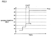
- Fig. 3 is a time chart representing by way of example the inner loop control of the mobile phone shown in Figs. 1 and 2.
- detected value P of the current or present sending power in a certain slot is equal to 20.5dBm, and the base station provides an instruction to increase the sending power by 5dB of the next slot.
- the sending power does not exceed the maximum sending power Pmax.
- the sending power can be substantially equal or close to maximum sending power Pmax so that the communication-allowed range of the mobile phone can be increased as compared with a conventional structure, in which the sending power is set to a low value.
- variable gain amplifiers 11 and 13 amplify the sending power for controlling the sending power.
- a variable gain attenuator may be employed to attenuate the send signal for controlling the sending power.
- Storage portion 17 stores a table representing the relationships between the sending power Pout and control voltage Vc of variable gain amplifiers 11 and 13.
- storage portion 17 may store functions representing such relationships instead of the table, in which case gain control portion 16 obtains control voltage Vc based on power control signal Pc, detected power value Px and such functions.
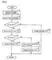
- a modification shown in Fig. 4 employs steps S21 and S22 in addition to those in Fig. 2.
- the detection range of sending power detecting portion 15 cannot be increased infinitely, and is restricted to a certain range. As this detection range is reduced, the sending power can be detected more accurately, and the structure of sending power detecting portion 15 can be further simplified.
- a difference (Pmax - Pa) between maximum sending power Pmax and lower limit Pa of detection range (Pa - Pb) of sending power detecting portion 15 is set to a value substantially equal to or slightly larger than the maximum change amount, by which the sending power can be increased at a time.
- Gain control portion 16 detects sending power Px by sending power detecting portion 15 in step S2, and determines in next step S21 whether sending power Px falls within the detection range between Pa - Pb or not. When it is determined in step S21 that a relationship of (Pa ⁇ Px ⁇ Pb) is satisfied, gain control portion 16 executes steps S3 - S7 already described in Fig. 2. When it is determined in step S21 that the relationship of (Pa ⁇ Px ⁇ Pb) is not satisfied, gain control portion 16 increases or decreases the sending power of the next slot by ⁇ P in step S22. It is assumed that the sending power does not exceed Pb because performances of amplifiers 11, 13 and 14 and others restrict such exceeding.
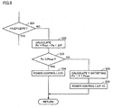
- a step S31 is employed instead of step S21 in the modification shown in Fig. 4, and steps S32 - S36 are employed instead of step S22 in Fig. 4.
- a detection range between PA and PB of sending power detecting portion 15 is smaller than the detection range between Pa - Pb in the modification shown in Fig. 4. More specifically, there is a relationship of (Pa ⁇ PA ⁇ Pmax ⁇ PB ⁇ Pb). This is because the narrower detection range allows more accurate detection of the sending power in the detection range, and can simplify tne structure of sending power detecting portion 15. In this modification, therefore, gain control portion 16 determines in step S31 whether a relationship of (PA ⁇ Px ⁇ PB) is satisfied.
- Pout represents the sending power of the current slot determined from control voltage Vc
- Pe represents a maximum value of an error in Pout.
- gain control portion 16 determines in step S33 that a relationship of (Px' ⁇ Pmax) is satisfied, it increases or decreases the sending power of the next sending power by ⁇ P in step S34.
- gain control portion 16 determines in step S33 that the relationship of (Px' ⁇ Pmax) is not satisfied, it calculates a value Y satisfying a relationship of (Px' - Y ⁇ Pmax) in step S35, and increases the sending power by ( ⁇ P - Y) in step S36.
- a modification shown in Fig. 6 employs a temperature detecting portion 20, a storage portion 21 and a correcting portion 22 added to sending power 9 shown in Fig. 1.
- Temperature detecting portion 20 detects a temperature T of sending power detecting portion 15.
- the detected value Px of sending power detecting portion 15 changes with temperature T. Therefore, storage portion 21 stores a table or functions representing relationships between temperature T and detected power value Px.
- Correcting portion 22 obtains a correction value of the detected power value based on temperature T of sending power detecting portion 15 detected by temperature detecting portion 20 and the table or functions stored in storage portion 21, and adds the correction value to detected power value Px.
- a detected power value Px1 thus corrected is applied to gain control portion 16 instead of value Px.
- the sending power can be detected more accurately.
- a storage portion 23 and a correcting portion 24 are added to sending portion 9 in Fig. 1.
- Detection value Px of sending power detecting portion 15 changes with a send frequency f.
- storage portion 23 stores a table or functions representing relationships between send frequency f and the correction value of detected power value Px.
- Send frequency f is detected by baseband/control portion 8 in Fig. 1.
- Correcting portion 24 obtains the correction value of the detected power value based on send frequency f detected by baseband/control portion 8 and the table or functions stored in storage portion 23, and adds the correction value to detected power value Px.
- Detected power value Px2 thus corrected is applied to gain control portion 16 instead of Px.
- detected power value Px is corrected based on send frequency f so that the sending power can be detected more accurately.
Landscapes
- Engineering & Computer Science (AREA)
- Computer Networks & Wireless Communication (AREA)
- Signal Processing (AREA)
- Mobile Radio Communication Systems (AREA)
- Transmitters (AREA)
Abstract
In a mobile phone according to the invention, a sum of a power
control amount (ΔP) instructed by a base station and a sending power (Px)
detected by a sending power detecting portion (15) obtained to calculate a
sending power (Px') for a next slot (S1 - S3), it is determined whether the
sending power (Px') is equal to or lower than a maximum sending power
(Pmax) or not (S4), a power control is performed in accordance with an
instruction of the base station when a relationship of (Px' ≤ Pmax) is
present (S5), a value X satisfying (Px' - X ≤ Pmax) is calculated when the
relationship of (Px' ≤ Pmax) is not present (S6), and the sending power is
changed by (ΔP - X) (S7).
Description
The present invention relates to mobile phone, and particularly
relates to a mobile phone for controlling a sending power in accordance
with an instruction applied from a base station.
Conventionally, a sending power of a mobile phone is controlled to
take an optimum value in accordance with a position and others of the
mobile phone so that communication with a base station can be performed
without impeding communication between other mobile phones and base
stations. Further, the maximum sending power is restricted not to exceed
a predetermined value (e.g., 25dBm).
The sending power of mobile phone is controlled in two stages for
open loop control and inner loop control. In the open loop control, the
mobile phone calculates a required sending power based on a receiving
power, and starts sending with the calculated power. In the inner loop
control, the base station gives the mobile phone an instruction for
increasing or decreasing the sending power in accordance with changes in
position of the mobile phone and others. In the inner loop control, the
sending power is also increased or decreased for reasons on the mobile
phone side (e.g., DTX).
Fig. 8 is a flowchart representing inner loop control of a conventional
mobile phone. In Fig. 8, a mobile phone calculates a power control amount
ΔP in a step S51 based on, e.g., signals sent from a base station, and detects
a sending power Px of a current or present slot in a step S5 for determining
in a step S53 whether sending power Px is equal to or smaller than a
predetermined threshold power Plim or not. When it is determined in step
S53 that sending power Px is equal to or smaller than predetermined
threshold power Plim, the sending power of the next slot is increased or
decreased by ΔP in a step S54. When it is determined in step S53 that
sending power Px is larger than predetermined threshold power Plim, the
power control is not performed.
Fig. 9 is a time chart representing by way of example the inner loop
control of the mobile phone already described with reference to Fig. 8. In
Fig. 9, an allowed maximum sending power is in a range Pmaxr from
21dBm to 25dBm, a maximum sending power Pmax is equal to 25dBm, and
threshold power Plim is set to 23dBm. Fig. 9 represents a case where a
mobile phone receives an instruction for every slot from a base station to
increase the sending power by 1dB. When sending power Px exceeds
threshold power Plim of 23 dBm, the mobile phone does not increase the
sending power even if the base station provides the instruction to increase
the sending power. This prevents sending power Px from exceeding
maximum sending power Pmax.
In the case shown in Fig. 9, no problem occurs as long as the base
station instructs the mobile phone to increase sending power Px by 1dB or
2dB. However, sending power Px will exceed maximum sending power
Pmax when an instruction for increasing sending power Px by 3dB or more
is provided. Alternatively, if threshold power Plim is set to a low value, it
is possible to prevent sending power Px from exceeding maximum sending
power Pmax. However, this reduces a communication-allowed range
because sending power Px is set to a lower value.
Accordingly, a major object of the invention is to provide a mobile
phone, which has a sending power not exceeding a maximum sending
power, and also has a large communication-allowed range.
For achieving the above object, the invention provides a mobile
phone including a receiving portion for receiving a signal from a base
station; a sending portion capable of control of a sending power for sending
a signal to the base station; a power calculating portion for determining a
power increase amount of a next slot based on a power control command or
the like applied from the base station via the receiving portion; a
determining portion for obtaining a first sum of the sending power of a
current slot and the power increase amount determined by the power
calculating portion, and determining whether the first sum is smaller than
a predetermined maximum sending power or not; and a power control
portion for increasing the sending power of the next slot of the sending
portion by the power increase amount obtained by the power calculating
portion when the determining portion determines that the first sum is
smaller than the maximum sending power, and for calculating the power
increase amount providing the sending power of the sending portion not
exceeding the maximum sending power, and increasing the sending power
of the next slot of said sending portion by the calculated power increase
amount when the determining portion determines that the first sum
exceeds the maximum sending power.
As a major advantage of the invention, when it is determined that
the sending power will exceed the maximum sending power if the sending
power is increased by the power increase amount determined based on, e.g.,
power control commands applied from the base station, the calculation is
made to provide the sending power not exceeding the maximum sending
power, and the sending power is increased only by the calculated power
increase amount. Therefore, the sending power does not exceed the
maximum sending power. The sending power can be equal to the
maximum sending power when necessary. This increases a
communication-allowed range as compared with a conventional structure,
in which the set sending power is relatively low.
Preferably, the sending portion includes a variable gain
amplifier/attenuator for amplifying or attenuating a send signal with a
gain according to a control signal. The mobile phone further includes a
storage portion for storing a table or a function representing a relationship
between the control signal and the sending power of the sending portion.
The power control portion controls the sending power of the sending portion
by applying the control signal to the variable gain amplifier/attenuator
based on the table or function stored in the storage portion. This structure
allows each control of the sending power.
More preferably, the mobile phone includes a power detecting portion
for detecting the sending power of the sending portion, and the sending
power of the current slot used in the determining portion is detected by the
power detecting portion.
Preferably, the power detecting portion has a predetermined power
detection range, and a lower limit of the power detection range is set to a
value lower than the maximum sending power by a value equal to or larger
than a maximum value of the power increase amount obtained by the
power calculating portion. The power control portion increases the
sending power of the sending portion by the power increase amount
determined by the power calculating portion independently of results of
determination of the determining portion when the sending power of the
sending portion is outside the power detection range of the power detecting
portion. This can reduce the power detection range of the power detecting
portion so that the detection accuracy of the power detecting portion can be
improved, and the structure can be simplified.
Preferably, the power detecting portion has a predetermined power
detection range. When the sending power of the sending portion is outside
the power detection range of the power detecting portion, the determining
portion obtains a second sum of the sending power of the sending portion
determined from the control signal, a maximum value of an error in the
sending power and the power increase amount of the next slot obtained by
the power calculating portion, and determines whether the second sum is
smaller than the maximum sending power or not. The power control
portion increases the sending power of the sending portion by the power
increase amount obtained by the power calculating portion when the second
sum is smaller than the maximum sending power according to the
determination of the determining portion. The power control portion
calculates the power increase amount providing the sending power of the
sending portion not exceeding the maximum sending power, and increases
the sending power of the sending portion by the calculated power increase
amount when the second sum is larger than the maximum sending power
according to the determination of the determining portion. This structure
can further reduce the power detection range of the power detecting portion
so that the detection accuracy of the power detecting portion can be further
improved, and the structure can be further simplified.
Preferably, the mobile phone further includes a temperature
detecting portion for detecting a temperature of the power detecting portion,
and a first correcting portion for correcting a detected value of the power
detecting portion based on the results of detection of the temperature
detecting portion.
More preferably, the mobile phone further includes a frequency
detecting portion for detecting a send frequency of the sending portion, and
a second correcting portion for correcting the detected value of the power
detecting portion based on the results of detection of the frequency
detecting portion.
Fig. 1 is a block diagram showing a major portion of a mobile phone
using a W-CDMA format according to an embodiment of the invention. In
Fig. 1, the mobile phone includes an antenna 1, a duplexer 2, a receiving
portion 3, a baseband/control portion 8 and a sending portion 9.
A high-frequency signal, which is sent from a base station and is
received by antenna 1, is supplied to receiving portion 3 via duplexer 2.
Duplexer 2 is provided for preventing input of a received signal into
sending portion 9 as well as input of a send signal into receiving portion 3.
Receiving portion 3 includes a low-noise amplifier 4, a mixer 5, a variable
gain amplifier 6 and an orthogonal demodulator 7.
The high-frequency signal supplied to receiving portion 3 is
amplified by low-noise amplifier 4, and is applied to mixer 5. Mixer 5
mixes the received high-frequency signal and an output signal of a local
oscillator (not shown) to produce an IF signal. The IF signal is amplified
by variable gain amplifier 6 to a predetermined power, and is applied to
orthogonal demodulator 7. Baseband/control portion 8 produces a control
voltage Vc6 of variable gain amplifier 6.
Orthogonal demodulator 7 demodulates the IF signal to produce and
apply a baseband signal to baseband/control portion 8. The baseband
signal is demodulated and converted into a digital signal by
baseband/control portion 8, and is further processed to produce an audio
signal.
Conversely, the audio signal or the like is subjected to predetermined
processing, and is converted thereby into a digital signal, which is then
demodulated and converted into a baseband signal by baseband/control
portion 8. The baseband signal thus produced is input to sending portion
9. Sending portion 9 includes an orthogonal modulator 10, variable gain
amplifiers 11 and 13, a mixer 12, a high-power amplifier 14, a sending
power detecting portion 15, a gain control portion 16 and a storage portion
17.
The baseband signal supplied to sending portion 9 is modulated and
converted into the IF signal by orthogonal modulator 10. The IF signal is
amplified by variable gain amplifier 11, and is applied to mixer 12. Mixer
12 mixes the received IF signal and an output signal of a local oscillator
(not shown) to produce a high-frequency signal. The high-frequency signal
is amplified by variable gain amplifier 13 and high-power amplifier 14, and
is sent to the base station via sending power detecting portion 15, duplexer
2 and antenna 1.
Sending power detecting portion 15 detects a power of the high-frequency
signal, and applies a detected value Px to gain control portion 16.
Storage portion 17 stores a table representing a relationship between a
sending power Pout and a control voltage Vc of variable gain amplifiers 11
and 13. Gain control portion 16 reads out an intended value of control
voltage Vc from storage portion 17 in accordance with a power control
signal Pc sent from baseband/control portion 8 and detected value Px of the
sending power applied from sending power detecting portion 15, and
applies control voltage Vc of the value thus read to variable gain amplifiers
11 and 13 for controlling the sending power.
Description will now be given on a manner of controlling the sending
power of the mobile phone. For communication with the base station, open
loop control is first performed. More specifically, baseband/control portion
8 produces control voltage Vc6 of variable gain amplifier 6 so that the
baseband signal of a predetermined power may be input. Based on control
voltage Vc6 thus produced, the receiving power applied from the base
station is calculated, and the required sending power is calculated based on
the receiving power. As the receiving power decreases, the required
sending power increases. As the receiving power increases, the required
sending power decreases. The sending power is set to a required
minimum power so as not to interfere with communication of other mobile
phones. Allowed range Pmaxr of the maximum sending power is
determined to be between 24dBm - 3dB and 24dBm + 1dB.
Baseband/control portion 8 applies power control signal Pc indicating
the calculated sending power to gain control portion 16. Gain control
portion 16 reads out a value of control voltage Vc corresponding to signal Pc,
and applies control voltage Vc of the value thus read to each of variable
gain amplifiers 11 and 13. Baseband/control portion 8 waits for return of
a reception acceptance signal from the base station. When the reception
acceptance signal is not returned, baseband/control portion 8 increases the
sending power by a predetermined power, and will repeat this increase
until the reception acceptance signal is returned. When the base station
returns the reception acceptance signal, the open loop control ends, and the
inner loop control starts.
According to the inner loop control, the base station instructs the
mobile phone to increase or decrease the sending power. This is done for
correcting the sending power when the communication conditions change,
e.g., due to movement of a user of the mobile phone. The control amount,
by which the sending power is increased or decreased, can be selected from
three kinds of values, i.e., ±1dB, ±2dB and ±3dB. Also, DTX control may
be performed such that the sending power is decreased by several decibels
when a voice disappears during voice communication. The sending power
is also changed by several decibels when an information rate (□) changes.
In the inner loop control, power control signal Pc applied from
baseband/control portion 8 to gain control portion 16 forms a signal
indicating an amount of increase/decrease of the sending power.
Fig. 2 is a flowchart showing the inner loop control of the mobile
phone shown in Fig. 1. Gain control portion 16 calculates an
increase/decrease amount, i.e., a power control amount ΔP of the sending
power based on power control signal Pc sent from baseband/control portion
8. Then, gain control portion 16 detects sending power Px of the current
slot by sending power detecting portion 15 in a step S2, calculates a
sending power Px' (= Px + ΔP) of the next slot in a step S3, and determines
in a step S4 whether sending power Px' is equal to or lower than maximum
sending power Pmax or not. When it is determined in step S4 that
sending power Px' is equal to or smaller than maximum sending power
Pmax, gain control portion 16 controls and changes control voltage Vc of
variable gain amplifiers 11 and 13 by ΔP in a step S5.
When gain control portion 16 determines in step S4 that sending
power Px' is larger than maximum sending power Pmax, a value X
satisfying a relationship of (Px' - X ≤ Pmax) is calculated in a step S6, and
control voltage Vc of variable gain amplifiers 11 and 13 is controlled in a
step S7 to change the sending power by (ΔP - X). The foregoing steps S1 -
S7 are executed for every slot.
Fig. 3 is a time chart representing by way of example the inner loop
control of the mobile phone shown in Figs. 1 and 2.
It is assumed that detected value P of the current or present sending
power in a certain slot is equal to 20.5dBm, and the base station provides
an instruction to increase the sending power by 5dB of the next slot. In
this case, gain control portion 16 calculates sending power Px' of the next
slot to obtain Px' = 25.5dBm (= 20.5 + 5), and determines that the sending
power Px' will exceed maximum sending power Pmax = 25dBm. Thereby,
gain control portion 16 calculates value X (e.g., equal to 1) satisfying the
relationship of (25.5 - X ≤ 25), and increases the sending power by 4dB (= 5
- 1) of the next slot.
According to this embodiment, therefore, the sending power does not
exceed the maximum sending power Pmax. Further, the sending power
can be substantially equal or close to maximum sending power Pmax so
that the communication-allowed range of the mobile phone can be
increased as compared with a conventional structure, in which the sending
power is set to a low value.
In this embodiment, variable gain amplifiers 11 and 13 amplify the
sending power for controlling the sending power. Alternatively, a variable
gain attenuator may be employed to attenuate the send signal for
controlling the sending power. Storage portion 17 stores a table
representing the relationships between the sending power Pout and control
voltage Vc of variable gain amplifiers 11 and 13. However, storage portion
17 may store functions representing such relationships instead of the table,
in which case gain control portion 16 obtains control voltage Vc based on
power control signal Pc, detected power value Px and such functions.
Modifications of the embodiment will now be described. A
modification shown in Fig. 4 employs steps S21 and S22 in addition to
those in Fig. 2. The detection range of sending power detecting portion 15
cannot be increased infinitely, and is restricted to a certain range. As this
detection range is reduced, the sending power can be detected more
accurately, and the structure of sending power detecting portion 15 can be
further simplified. In this modification, therefore, a difference (Pmax - Pa)
between maximum sending power Pmax and lower limit Pa of detection
range (Pa - Pb) of sending power detecting portion 15 is set to a value
substantially equal to or slightly larger than the maximum change amount,
by which the sending power can be increased at a time.
Gain control portion 16 detects sending power Px by sending power
detecting portion 15 in step S2, and determines in next step S21 whether
sending power Px falls within the detection range between Pa - Pb or not.
When it is determined in step S21 that a relationship of (Pa ≤ Px ≤ Pb) is
satisfied, gain control portion 16 executes steps S3 - S7 already described in
Fig. 2. When it is determined in step S21 that the relationship of (Pa ≤ Px
≤ Pb) is not satisfied, gain control portion 16 increases or decreases the
sending power of the next slot by ΔP in step S22. It is assumed that the
sending power does not exceed Pb because performances of amplifiers 11,
13 and 14 and others restrict such exceeding.
In a modification shown in Fig. 5, a step S31 is employed instead of
step S21 in the modification shown in Fig. 4, and steps S32 - S36 are
employed instead of step S22 in Fig. 4. Further, a detection range
between PA and PB of sending power detecting portion 15 is smaller than
the detection range between Pa - Pb in the modification shown in Fig. 4.
More specifically, there is a relationship of (Pa < PA < Pmax ≤ PB ≤ Pb).
This is because the narrower detection range allows more accurate
detection of the sending power in the detection range, and can simplify tne
structure of sending power detecting portion 15. In this modification,
therefore, gain control portion 16 determines in step S31 whether a
relationship of (PA ≤ Px ≤ PB) is satisfied. When it is determined that the
relationship of (PA ≤ Px ≤ PB) is not satisfied, sending power Px' (= Pout +
Pe + ΔP) of the next slot is calculated in step S32, and it is determined in
step S33 whether the sending power Px' is equal to or lower than maximum
sending power Pmax or not. In the above formula, Pout represents the
sending power of the current slot determined from control voltage Vc, and
Pe represents a maximum value of an error in Pout.
When gain control portion 16 determines in step S33 that a
relationship of (Px' ≤ Pmax) is satisfied, it increases or decreases the
sending power of the next sending power by ΔP in step S34. When gain
control portion 16 determines in step S33 that the relationship of (Px' ≤
Pmax) is not satisfied, it calculates a value Y satisfying a relationship of
(Px' - Y ≤ Pmax) in step S35, and increases the sending power by (ΔP - Y) in
step S36.
A modification shown in Fig. 6 employs a temperature detecting
portion 20, a storage portion 21 and a correcting portion 22 added to
sending power 9 shown in Fig. 1. Temperature detecting portion 20
detects a temperature T of sending power detecting portion 15. The
detected value Px of sending power detecting portion 15 changes with
temperature T. Therefore, storage portion 21 stores a table or functions
representing relationships between temperature T and detected power
value Px. Correcting portion 22 obtains a correction value of the detected
power value based on temperature T of sending power detecting portion 15
detected by temperature detecting portion 20 and the table or functions
stored in storage portion 21, and adds the correction value to detected
power value Px. A detected power value Px1 thus corrected is applied to
gain control portion 16 instead of value Px. In this modification, since
detected power value Px is corrected based on temperature T, the sending
power can be detected more accurately.
In a modification shown in Fig. 7, a storage portion 23 and a
correcting portion 24 are added to sending portion 9 in Fig. 1. Detection
value Px of sending power detecting portion 15 changes with a send
frequency f. Accordingly, storage portion 23 stores a table or functions
representing relationships between send frequency f and the correction
value of detected power value Px. Send frequency f is detected by
baseband/control portion 8 in Fig. 1. Correcting portion 24 obtains the
correction value of the detected power value based on send frequency f
detected by baseband/control portion 8 and the table or functions stored in
storage portion 23, and adds the correction value to detected power value
Px. Detected power value Px2 thus corrected is applied to gain control
portion 16 instead of Px. In this modification, detected power value Px is
corrected based on send frequency f so that the sending power can be
detected more accurately.
Although the present invention has been described and illustrated in
detail, it is clearly understood that the same is by way of illustration and
example only and is not to be taken by way of limitation, the spirit and
scope of the present invention being limited only by the terms of the
appended claims.
Claims (7)
- A mobile phone comprising:a receiving portion (3, 8) for receiving a signal from a base station;a sending portion (10 - 14) capable of control of a sending power for sending a signal to said base station;a power calculating portion (16, S1) for determining a power increase amount (ΔP) of a next slot based on a power control command or the like applied from said base station via said receiving portion (3, 8);a determining portion (16, S2 - S4) for obtaining a first sum (Px + ΔP) of the sending power (Px) of a current slot and the power increase amount (ΔP) determined by said power calculating portion (16, S1) and determining whether said first sum (Px + ΔP) is smaller than a predetermined maximum sending power (Pmax) or not; anda power control portion (16, S5 - S7) for increasing the sending power of the next slot of said sending portion (10 - 14) by the power increase amount (ΔP) obtained by said power calculating portion (16, S1) when said determining portion (16, S2 - S4) determines that said first sum (Px + ΔP) is smaller than said maximum sending power (Pmax), and for calculating the power increase amount (ΔP - X) providing the sending power of said sending portion (10 - 14) not exceeding said maximum sending power (Pmax), and increasing the sending power of the next slot of said sending portion (10 - 14) by the calculated power increase amount (ΔP - X) when said determining portion (16, S2 - S4) determines that said first sum (Px + ΔP) exceeds said maximum sending power (Pmax).
- The mobile phone according to claim 1, wherein
said sending portion (10 - 14) includes a variable gain amplifier/attenuator (11, 13) for amplifying or attenuating a send signal with a gain according to a control signal (Vc),
said mobile phone further comprises a storage portion (17) for storing a table or a function representing a relationship between said control signal (Vc) and a sending power (Pout) of said sending portion (10 - 14), and
said power control portion (16, S5 - S7) controls the sending power (Pout) of said sending portion (10 - 14) by applying the control signal (Vc) to said variable gain amplifier/attenuator (11, 13) based on said table or function stored in said storage portion (17). - The mobile phone according to claim 2, further comprising:a power detecting portion (15) for detecting the sending power (Px) of said sending portion (10 - 14), whereinsaid sending power (Px) of said current slot used in said determining portion (16, S2 - S4) is detected by said power detecting portion (15).
- The mobile phone according to claim 3, wherein
said power detecting portion (15) has a predetermined power detection range (Pa - Pb), and a lower limit (Pa) of said power detection range (Pa - Pb) is set to a value lower than said maximum sending power (Pmax) by a value equal to or larger than a maximum value of the power increase amount (ΔP) obtained by said power calculating portion (16, S1), and
said power control portion (16, S5 - S7, S21, S22) increases the sending power of said sending portion (10 - 14) by the power increase amount (ΔP) determined by said power calculating portion (16, S1) independently of results of determination of said determining portion (16, S2 - S4) when the sending power of said sending portion (10 - 14) is outside the power detection range of said power detecting portion (15). - The mobile phone according to claim 3,
said power detecting portion (15) has a predetermined power detection range (PA - PB);
when the sending power of said sending portion (10 - 14) is outside the power detection range of said power detecting portion (15), said determining portion (16, S31 - S33) obtains a second sum (Pout + Pe + ΔP) of the sending power (Pout) of said sending portion (10 - 14) determined from said control signal (Vc), a maximum value (Pe) of an error in said sending power (Pout) and the power increase amount (ΔP) of the next slot obtained by the power calculating portion (16, S1), and determines whether said second sum (Pout + Pe + ΔP) is smaller than said maximum sending power (Pmax) or not; and
said power control portion (16, S5 - S7, S34 - S36) increases the sending power of said sending portion (10 - 14) by the power increase amount (ΔP) obtained by said power calculating portion (16, S1) when said second sum (Pout + Pe + ΔP) is smaller than said maximum sending power (Pmax) according to the determination of said determining portion (16, S31 - S33), and said power control portion (16, S5 - S7, S34 - S36) calculates the power increase amount (ΔP- Y) providing the sending power of said sending portion (10 - 14) not exceeding said maximum sending power (Pmax), and increases the sending power of said sending portion (10 - 14) by said calculated power increase amount (ΔP - Y) when said second sum (Pout + Pe + ΔP) is larger than said maximum sending power (Pmax) according to the determination of said determining portion (16, S31 - S33). - The mobile phone according to claim 3, further comprising:a temperature detecting portion (20) for detecting a temperature of said power detecting portion (15); anda first correcting portion (21, 22) for correcting a detected value (Px) of said power detecting portion (15) based on the results of detection of said temperature detecting portion (20).
- The mobile phone according to claim 3, further comprising:a frequency detecting portion (8) for detecting a send frequency of said sending portion (10 - 14), anda second correcting portion (23, 24) for correcting the detected value (Px) of said power detecting portion (15) based on the results of detection of said frequency detecting portion (8).
Applications Claiming Priority (1)
| Application Number | Priority Date | Filing Date | Title |
|---|---|---|---|
| PCT/JP2000/008009 WO2002039603A1 (en) | 2000-11-13 | 2000-11-13 | Portable telephone |
Publications (2)
| Publication Number | Publication Date |
|---|---|
| EP1249941A1 true EP1249941A1 (en) | 2002-10-16 |
| EP1249941A4 EP1249941A4 (en) | 2005-01-19 |
Family
ID=11736682
Family Applications (1)
| Application Number | Title | Priority Date | Filing Date |
|---|---|---|---|
| EP00974974A Withdrawn EP1249941A4 (en) | 2000-11-13 | 2000-11-13 | CELLPHONE |
Country Status (5)
| Country | Link |
|---|---|
| US (1) | US6832098B1 (en) |
| EP (1) | EP1249941A4 (en) |
| JP (1) | JP3843259B2 (en) |
| CN (1) | CN1192488C (en) |
| WO (1) | WO2002039603A1 (en) |
Cited By (1)
| Publication number | Priority date | Publication date | Assignee | Title |
|---|---|---|---|---|
| US8644874B2 (en) | 2008-01-07 | 2014-02-04 | Telefonaktiebolaget L M Ericsson (Publ) | Uplink power control for power limited terminals |
Families Citing this family (4)
| Publication number | Priority date | Publication date | Assignee | Title |
|---|---|---|---|---|
| JP2005039367A (en) * | 2003-07-16 | 2005-02-10 | Toshiba Corp | Cell search control method for mobile communication terminal and mobile communication terminal |
| KR100595652B1 (en) * | 2004-02-12 | 2006-07-03 | 엘지전자 주식회사 | Apparatus and method for controlling transmit power in mobile communication terminal |
| JP2006195824A (en) * | 2005-01-14 | 2006-07-27 | Adc Technology Kk | Cellular phone, alarm receiver and alarm system using the same |
| JP4383480B2 (en) * | 2007-11-15 | 2009-12-16 | 株式会社エヌ・ティ・ティ・ドコモ | Mobile communication terminal and transmission power control method in mobile communication terminal |
Family Cites Families (10)
| Publication number | Priority date | Publication date | Assignee | Title |
|---|---|---|---|---|
| JPH02285817A (en) * | 1989-04-27 | 1990-11-26 | Nec Corp | Radio transmitter |
| US5003868A (en) * | 1989-05-01 | 1991-04-02 | Alperk Limited | Food processing apparatus |
| JP2993554B2 (en) * | 1994-05-12 | 1999-12-20 | エヌ・ティ・ティ移動通信網株式会社 | Transmission power control method and communication device using the transmission power control method |
| US5551057A (en) * | 1994-06-08 | 1996-08-27 | Lucent Technologies Inc. | Cellular mobile radio system power control |
| JP3755704B2 (en) * | 1997-12-27 | 2006-03-15 | ソニー株式会社 | Transmission power control method, base station apparatus and communication terminal apparatus |
| US6466772B1 (en) * | 1998-09-25 | 2002-10-15 | Skyworks Solutions, Inc. | Apparatus and method for improving power control loop linearity |
| US6377798B1 (en) * | 1999-01-22 | 2002-04-23 | Siemens Information And Communication Networks, Inc. | System and method for improved wireless telephone call reception notification |
| JP2000224104A (en) * | 1999-01-29 | 2000-08-11 | Toshiba Corp | Mobile radio communication terminal, mobile communication system and radio base station |
| JP3618055B2 (en) * | 1999-02-05 | 2005-02-09 | 富士通株式会社 | Portable mobile terminal and transmitter |
| JP4023025B2 (en) * | 1999-03-26 | 2007-12-19 | 株式会社デンソー | Wireless communication apparatus and transmission power control method for wireless communication apparatus |
-
2000
- 2000-11-13 US US10/148,183 patent/US6832098B1/en not_active Expired - Fee Related
- 2000-11-13 EP EP00974974A patent/EP1249941A4/en not_active Withdrawn
- 2000-11-13 JP JP2002541809A patent/JP3843259B2/en not_active Expired - Fee Related
- 2000-11-13 CN CNB008180873A patent/CN1192488C/en not_active Expired - Fee Related
- 2000-11-13 WO PCT/JP2000/008009 patent/WO2002039603A1/en not_active Ceased
Cited By (4)
| Publication number | Priority date | Publication date | Assignee | Title |
|---|---|---|---|---|
| US8644874B2 (en) | 2008-01-07 | 2014-02-04 | Telefonaktiebolaget L M Ericsson (Publ) | Uplink power control for power limited terminals |
| US9313751B2 (en) | 2008-01-07 | 2016-04-12 | Telefonaktiebolaget Lm Ericsson (Publ) | Uplink power control for power limited terminals |
| US10104623B2 (en) | 2008-01-07 | 2018-10-16 | Telefonaktiebolaget Lm Ericsson (Publ) | Uplink power control for power limited terminals |
| US11743832B2 (en) | 2008-01-07 | 2023-08-29 | Telefonaktiebolaget Lm Ericsson (Publ) | Uplink power control for power limited terminals |
Also Published As
| Publication number | Publication date |
|---|---|
| CN1192488C (en) | 2005-03-09 |
| US6832098B1 (en) | 2004-12-14 |
| WO2002039603A1 (en) | 2002-05-16 |
| JPWO2002039603A1 (en) | 2004-03-18 |
| CN1415138A (en) | 2003-04-30 |
| EP1249941A4 (en) | 2005-01-19 |
| JP3843259B2 (en) | 2006-11-08 |
Similar Documents
| Publication | Publication Date | Title |
|---|---|---|
| US7039373B2 (en) | Wireless communication apparatus and transmission power control method thereof | |
| CA2109810C (en) | Power control circuitry for achieving wide dynamic range in a transmitter | |
| JP3358598B2 (en) | Transmission power correction circuit | |
| EP0961402A2 (en) | A transmitter | |
| US8160630B2 (en) | Method and arrangement for controlling transmission power and a network element | |
| CN101529718A (en) | Transmission method and transmission device | |
| US6970715B2 (en) | Portable wireless transceiver controlling transmission power | |
| JP2000196521A (en) | Wireless communication device and transmission power control method in wireless communication device | |
| EP1249941A1 (en) | Portable telephone | |
| JPH11220410A (en) | Rf transmitter with temperature compensated output power level control circuit and temperature compensation method | |
| US7640033B2 (en) | Radio communication apparatus and transmission power control method | |
| JP4903217B2 (en) | Transmission method and transmission apparatus | |
| JP4023025B2 (en) | Wireless communication apparatus and transmission power control method for wireless communication apparatus | |
| KR100293367B1 (en) | Control circuit and control method for mobile station transmission power in mobile communication system | |
| EP1093233A1 (en) | Apparatus and method for power control | |
| EP1675275A2 (en) | Apparatus for limiting maximum transmission power and method thereof | |
| JP3890264B2 (en) | Radio device transmitter and transmission level control method thereof | |
| US6687490B2 (en) | Transmission apparatus and method for a mobile communication terminal | |
| JP2000091929A (en) | Mobile terminal | |
| WO2007096281A1 (en) | Output power control with timeslot based operation mode switching | |
| KR20040061801A (en) | Apparatus and Method of Transmitting Power Control Using Power Ditector |
Legal Events
| Date | Code | Title | Description |
|---|---|---|---|
| PUAI | Public reference made under article 153(3) epc to a published international application that has entered the european phase |
Free format text: ORIGINAL CODE: 0009012 |
|
| 17P | Request for examination filed |
Effective date: 20020813 |
|
| AK | Designated contracting states |
Kind code of ref document: A1 Designated state(s): AT BE CH CY DE DK ES FI FR GB GR IE IT LI LU MC NL PT SE |
|
| RBV | Designated contracting states (corrected) |
Designated state(s): DE FR GB |
|
| A4 | Supplementary search report drawn up and despatched |
Effective date: 20041207 |
|
| 17Q | First examination report despatched |
Effective date: 20050214 |
|
| STAA | Information on the status of an ep patent application or granted ep patent |
Free format text: STATUS: THE APPLICATION HAS BEEN WITHDRAWN |
|
| 18W | Application withdrawn |
Effective date: 20050628 |