EP1249927A2 - Method and system for converting single phase alternating current to multiple phase alternating current - Google Patents
Method and system for converting single phase alternating current to multiple phase alternating current Download PDFInfo
- Publication number
- EP1249927A2 EP1249927A2 EP20020252464 EP02252464A EP1249927A2 EP 1249927 A2 EP1249927 A2 EP 1249927A2 EP 20020252464 EP20020252464 EP 20020252464 EP 02252464 A EP02252464 A EP 02252464A EP 1249927 A2 EP1249927 A2 EP 1249927A2
- Authority
- EP
- European Patent Office
- Prior art keywords
- phase
- alternating current
- path
- power
- recited
- Prior art date
- Legal status (The legal status is an assumption and is not a legal conclusion. Google has not performed a legal analysis and makes no representation as to the accuracy of the status listed.)
- Withdrawn
Links
Images
Classifications
-
- H—ELECTRICITY
- H02—GENERATION; CONVERSION OR DISTRIBUTION OF ELECTRIC POWER
- H02M—APPARATUS FOR CONVERSION BETWEEN AC AND AC, BETWEEN AC AND DC, OR BETWEEN DC AND DC, AND FOR USE WITH MAINS OR SIMILAR POWER SUPPLY SYSTEMS; CONVERSION OF DC OR AC INPUT POWER INTO SURGE OUTPUT POWER; CONTROL OR REGULATION THEREOF
- H02M5/00—Conversion of AC power input into AC power output, e.g. for change of voltage, for change of frequency, for change of number of phases
- H02M5/02—Conversion of AC power input into AC power output, e.g. for change of voltage, for change of frequency, for change of number of phases without intermediate conversion into DC
- H02M5/04—Conversion of AC power input into AC power output, e.g. for change of voltage, for change of frequency, for change of number of phases without intermediate conversion into DC by static converters
- H02M5/10—Conversion of AC power input into AC power output, e.g. for change of voltage, for change of frequency, for change of number of phases without intermediate conversion into DC by static converters using transformers
- H02M5/14—Conversion of AC power input into AC power output, e.g. for change of voltage, for change of frequency, for change of number of phases without intermediate conversion into DC by static converters using transformers for conversion between circuits of different phase number
Definitions
- This invention relates to a method and system for converting single phase alternating current to multiple phase alternating current, and in particular to utilizing a forty-two volt (42 V) power distribution system (42 V alternator, 36 V battery) to control multiple vehicle motors by converting single phase alternating current to three-phase alternating current.
- 42 V forty-two volt
- the automotive industry is moving towards a thirty-six volt (36V) / forty-two volt (42V) alternator system.
- hybrid systems that can support both voltages are needed. These hybrid systems are referred to as a twelve volt (12V) / thirty-six volt (36V) battery power distribution system or a fourteen volt (14V) / forty-two volt (42V) power distribution system.
- the use of a 36V/42V system permits the use of electrical components that could not previously be used in 12V/14V systems.
- the 36V/42V system provides direct current (DC) to power DC motors that run the various vehicle actuation systems such as window regulators, sunroofs, power locks, power mirrors, power seats, etc.
- AC induction motors require at least single-phase AC power (for single-phase induction motors); however, to operate efficiently and smoothly, three-phase Ac power is preferred (for three-phase induction motors).
- the use of AC induction motors requires conversion of the direct current power supply to three-phase alternating current.
- direct current is converted to three-phase alternating current by at least six (6) power switches and multiple wires leading into the power converter. This requires a complex circuit that is expensive.
- a system for converting single phase alternating current produced by pulse width modulation to three-phase alternating current uses lead/lag circuits to produce the phase shifts.
- the direct current source is provided by a twelve volt (12V) / thirty-six volt (36V) power distribution systems. This configuration permits the use of induction motors for operating vehicle systems such as power seats, power windows, door locks, etc., for example. Induction motors increase reliability and accuracy for overall improved system performance.
- the method for converting single phase alternating current to multiple phase alternating current to simultaneously power multiple vehicle systems includes the following steps.
- Single phase alternating current is produced from a direct current source with pulse width modulation.
- the single phase alternating current is split into a plurality of separate paths including at least a first path, a second path, and a third path.
- the phase of the alternating current on the second path is shifted to a different phase than the phase of the first path.
- the phase of the alternating current on the third path is shifted to a different phase than the phase first or second paths to create three-phase alternating current power.
- Multiple vehicle systems are operated by the three-phase alternating current power.
- the system for converting single phase alternating current to multiple phase alternating current to simultaneously power multiple vehicle systems includes a direct current source and a single pulse width modulation generator for converting direct current to alternating current.
- This provides one power supply path of alternating current having a first phase.
- a splitter splits the one power supply path of alternating current into a plurality of power supply paths including at least a first power supply path, a second power supply path, and a third power supply path.
- At least one lead/lag circuit shifts the alternating current of the second path to a second phase different than the first phase of the first power supply path and at least one lead/lag circuit shifts the alternating current of the third path to a third phase different than the first phase or the second phase.
- a plurality of induction motors operates multiple vehicle systems via a three-phase alternating current power comprised of the first, second, and third paths.
- This configuration provides a simplified and inexpensive means of converting direct current from a 36V power supply to three-phase alternating current power for operating induction motors.
- the induction motors operate efficiently and reliably to improve the performance of the respective vehicle system.
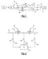
- a system for converting single phase alternating current into three-phase alternating current is shown schematically at 10 in Figure 1.
- the system 10 has a twelve volt (12V) /thirty-six volt (36V) battery power distribution system 14.
- the operation of batteries is well known in the art and thus will not be discussed in detail.
- the system 10 provides 12V power for vehicle operations that have traditionally required 12V power and provides 36V power for additional vehicle systems that require more power to operate accurately and efficiently.
- the 12V / 36V system provides direct current (DC) that is converted to alternating current (AC) to power induction motors 16 that run various vehicle operating systems 18 such as window regulators, sunroofs, power locks, power mirrors, power seats, etc., for example.
- a converter 20 comprised of a pulse width modulation (PWM) generator produces single phase alternating current 22 from the direct current source 14.
- a splitter 24 splits the single phase alternating current 22 into a plurality of separate alternating current paths including a first path 26a, a second path 26b, and a third path 26c.
- the first path 26a has a first phase 28 that is equivalent to the single phase alternating current 22.
- the second path 26b is shifted to a second phase 30 of alternating current that is different than the first phase 28.
- the third path 26c is shifted to a third phase 32 of alternating current that is different than the first 28 or second 30 phases. This creates three-phase alternating current power 34 that is used to operate induction motors 16 for the multiple vehicle systems 18.
- the single phase alternating current 22 is provided by a single wire that is tapped into at three (3) different locations.
- a first tap 38 is made into the single wire before phase shifting occurs, a second tap 40 occurs after the first phase shift, and a third tap 42 occurs after the second phase shift.
- the phase shifts are initiated by inductors 44 placed between the first 38 and second 40 taps and between the second 40 and third 42 taps.
- the inductors 44 create a time delay between the currents at each location, which results in the subsequent phase shift.
- the three-phase alternating current 34 is then supplied to the induction motor 16 to run the appropriate vehicle system 18.
- the second phase 30 is shifted by approximately one hundred and twenty degrees (120°) compared to the first phase 28 and the third phase 32 is shifted by approximately one hundred and twenty degrees (120°) compared to the second phase 30.
- the first phase 28 is maintained at approximately a zero degrees (0°) phase shift
- the second phase 30 is maintained at approximately a one hundred and twenty degrees (120°) phase shift
- the third phase 32 is maintained at approximately a two hundred and forty degrees (240°) phase shift.
Landscapes
- Engineering & Computer Science (AREA)
- Power Engineering (AREA)
- Control Of Multiple Motors (AREA)
- Electric Propulsion And Braking For Vehicles (AREA)
- Ac-Ac Conversion (AREA)
Abstract
Description
- This invention relates to a method and system for converting single phase alternating current to multiple phase alternating current, and in particular to utilizing a forty-two volt (42 V) power distribution system (42 V alternator, 36 V battery) to control multiple vehicle motors by converting single phase alternating current to three-phase alternating current.
- As more electrically controlled devices are incorporated into vehicles, the power supply for running these devices must also be increased. The standard twelve volt (12V) battery with a fourteen volt (14V) alternator that has traditionally been installed within the vehicle does not provide sufficient power to meet the increased demands.
- To meet the demand for an increased power supply, the automotive industry is moving towards a thirty-six volt (36V) / forty-two volt (42V) alternator system. As this transition is made, hybrid systems that can support both voltages are needed. These hybrid systems are referred to as a twelve volt (12V) / thirty-six volt (36V) battery power distribution system or a fourteen volt (14V) / forty-two volt (42V) power distribution system. The use of a 36V/42V system permits the use of electrical components that could not previously be used in 12V/14V systems. The 36V/42V system provides direct current (DC) to power DC motors that run the various vehicle actuation systems such as window regulators, sunroofs, power locks, power mirrors, power seats, etc.
- In a 36V/42V power system, there is sufficient power to use alternating current (AC) induction motors for running the various actuation systems in a vehicle. AC induction motors require at least single-phase AC power (for single-phase induction motors); however, to operate efficiently and smoothly, three-phase Ac power is preferred (for three-phase induction motors). Thus, the use of AC induction motors requires conversion of the direct current power supply to three-phase alternating current. Typically, direct current is converted to three-phase alternating current by at least six (6) power switches and multiple wires leading into the power converter. This requires a complex circuit that is expensive.
- On the other hand, conversion of direct current into single-phase alternating current can be performed simply by two (2) power switches. Thus it is desirable to provide a low-cost method and apparatus for converting single phase alternating current to three-phase alternating current to power induction motors without additional power switches.
- A system for converting single phase alternating current produced by pulse width modulation to three-phase alternating current, uses lead/lag circuits to produce the phase shifts. The direct current source is provided by a twelve volt (12V) / thirty-six volt (36V) power distribution systems. This configuration permits the use of induction motors for operating vehicle systems such as power seats, power windows, door locks, etc., for example. Induction motors increase reliability and accuracy for overall improved system performance.
- The method for converting single phase alternating current to multiple phase alternating current to simultaneously power multiple vehicle systems includes the following steps. Single phase alternating current is produced from a direct current source with pulse width modulation. The single phase alternating current is split into a plurality of separate paths including at least a first path, a second path, and a third path. The phase of the alternating current on the second path is shifted to a different phase than the phase of the first path. The phase of the alternating current on the third path is shifted to a different phase than the phase first or second paths to create three-phase alternating current power. Multiple vehicle systems are operated by the three-phase alternating current power.
- In a disclosed embodiment of this invention, the system for converting single phase alternating current to multiple phase alternating current to simultaneously power multiple vehicle systems includes a direct current source and a single pulse width modulation generator for converting direct current to alternating current. This provides one power supply path of alternating current having a first phase. A splitter splits the one power supply path of alternating current into a plurality of power supply paths including at least a first power supply path, a second power supply path, and a third power supply path. At least one lead/lag circuit shifts the alternating current of the second path to a second phase different than the first phase of the first power supply path and at least one lead/lag circuit shifts the alternating current of the third path to a third phase different than the first phase or the second phase. A plurality of induction motors operates multiple vehicle systems via a three-phase alternating current power comprised of the first, second, and third paths.
- This configuration provides a simplified and inexpensive means of converting direct current from a 36V power supply to three-phase alternating current power for operating induction motors. The induction motors operate efficiently and reliably to improve the performance of the respective vehicle system.
- These and other features of the present invention can be best understood from the following specification and drawings, the following of which is a brief description.
-
- Figure 1 is a schematic diagram incorporating the subject invention.
- Figure 2 is a schematic diagram depicting one embodiment of the invention incorporated into a vehicle system.
-
- A system for converting single phase alternating current into three-phase alternating current is shown schematically at 10 in Figure 1. The
system 10 has a twelve volt (12V) /thirty-six volt (36V) batterypower distribution system 14. The operation of batteries is well known in the art and thus will not be discussed in detail. Thesystem 10 provides 12V power for vehicle operations that have traditionally required 12V power and provides 36V power for additional vehicle systems that require more power to operate accurately and efficiently. The 12V / 36V system provides direct current (DC) that is converted to alternating current (AC) topower induction motors 16 that run variousvehicle operating systems 18 such as window regulators, sunroofs, power locks, power mirrors, power seats, etc., for example. - A
converter 20 comprised of a pulse width modulation (PWM) generator produces single phasealternating current 22 from the directcurrent source 14. Asplitter 24 splits the singlephase alternating current 22 into a plurality of separate alternating current paths including afirst path 26a, asecond path 26b, and athird path 26c. Thefirst path 26a has afirst phase 28 that is equivalent to the singlephase alternating current 22. Thesecond path 26b is shifted to asecond phase 30 of alternating current that is different than thefirst phase 28. Thethird path 26c is shifted to athird phase 32 of alternating current that is different than the first 28 or second 30 phases. This creates three-phase alternatingcurrent power 34 that is used to operateinduction motors 16 for themultiple vehicle systems 18. - The shifting of the second 30 and third 32 phases is accomplished with analog lead/
lag circuits 36. The operation of lead lag circuits is well known. In one embodiment, shown in Figure 2, the single phasealternating current 22 is provided by a single wire that is tapped into at three (3) different locations. Afirst tap 38 is made into the single wire before phase shifting occurs, a second tap 40 occurs after the first phase shift, and athird tap 42 occurs after the second phase shift. The phase shifts are initiated byinductors 44 placed between the first 38 and second 40 taps and between the second 40 and third 42 taps. Theinductors 44 create a time delay between the currents at each location, which results in the subsequent phase shift. The three-phasealternating current 34 is then supplied to theinduction motor 16 to run theappropriate vehicle system 18. - Preferably, the
second phase 30 is shifted by approximately one hundred and twenty degrees (120°) compared to thefirst phase 28 and thethird phase 32 is shifted by approximately one hundred and twenty degrees (120°) compared to thesecond phase 30. In the preferred embodiment, thefirst phase 28 is maintained at approximately a zero degrees (0°) phase shift, thesecond phase 30 is maintained at approximately a one hundred and twenty degrees (120°) phase shift, and thethird phase 32 is maintained at approximately a two hundred and forty degrees (240°) phase shift. - By generating only a single phase alternating current by pulse width modulation and converting the single phase into a three-phase alternating current, the number of wires leading out of the power converter is significantly reduced. Further, the number of for power switches is minimized. This significantly reduces the cost and makes the use of induction motors for operating vehicle systems much more economical.
- Although a preferred embodiment of this invention has been disclosed, it should be understood that a worker of ordinary skill in the art would recognize many modifications come within the scope of this invention. For that reason, the following claims should be studied to determine the true scope and content of this invention.
Claims (10)
- A method for converting single phase alternating current to multiple phase alternating current for simultaneously powering multiple vehicle systems comprising the steps of:(a) producing single phase alternating current (22) from a direct current source (14) with pulse width modulation;(b) splitting the single phase alternating current into a plurality of separate paths including at least a first path (26a), a second path (26b), and a third path (26c);(c) shifting the phase of the alternating current on the second path to be different than the phase of the first path and shifting the phase of the alternating current on the third path to be different than the phase first or second paths to create three-phase alternating current power (34); and(d) operating vehicle systems (18) with the three-phase alternating current power.
- A method as recited in claim 1, wherein step (c) further includes shifting the phase of the alternating current for the second and third paths with lead/lag (36) circuits.
- A method as recited in claim 1 or 2, wherein step (b) is further defined as splitting the single phase alternating current into only three separate paths comprised of the first path, the second path, and the third path.
- A method as recited in any one of claims 1 to 3, wherein step (c) is further defined as maintaining the first path at a first phase (28) corresponding to the phase of the single phase alternating current, shifting the single phase alternating current of the second path to a second phase (30) different than the first phase, and shifting the single phase alternating current of the third path to a third phase (32) different than the first or second phases.
- A method as recited in any preceding claim wherein step (b) further includes providing a single line for the single phase alternating current and tapping into the this same line at three different locations to create the first path, the second path, and the third path.
- A method as recited in claim 5 wherein step (c) further includes shifting the phase of the alternating current for the second and third paths with inductors (44) placed between the first and second paths on the single line and between the second and third paths on the single line.
- A system (10) for converting single phase alternating current (22) to multiple phase alternating current (34) to simultaneously power multiple vehicle systems (18) comprising:a direct current source (14);a single pulse width modulation generator (20) for converting direct current to alternating current to provide one power supply path of alternating current (27) having a first phase (28);a splitter (24) for splitting said one power supply path of alternating current into a plurality of power supply paths including at least a first power supply path (26a), a second power supply path (26b), and a third power supply path (26c);at least one lead/lag circuit (36) for shifting the alternating current of said second path to a second phase (30) different than said first phase of said first power supply path;at least one lead/lag circuit (36) for shifting the alternating current of said third path to a third phase (32) different than said first phase or said second phase; anda plurality of induction motors (16) for operating multiple vehicle systems (18) via a three-phase alternating current power (34) comprised of said first, second, and third paths.
- A system as recited in claim 7 or a method as recited in any one of claims 1 to 6, wherein said direct current source is a thirty-six volt (36V) battery power distribution system.
- A system as recited in claim 7 or 8, or a method as recited in claim 4 or claims 5, 6, or 8 when dependent on claim 4, wherein the second phase is shifted by approximately one hundred and twenty degrees (120°) compared to the first phase and the third phase is shifted by approximately one hundred and twenty degrees (120°) compared to the second phase.
- A system as recited in any one of claims 7 to 9, or a method as recited in claim 4 or claims 5, 6, or 8 when dependent on claim 4, wherein the first phase is maintained at approximately a zero degrees (0°) phase shift, the second phase is maintained at approximately a one hundred and twenty degrees (120°) phase shift, and the third phase is maintained at approximately a two hundred and forty degrees (240°) phase shift to provide the three-phase alternating current power.
Applications Claiming Priority (2)
| Application Number | Priority Date | Filing Date | Title |
|---|---|---|---|
| US09/832,677 US6831849B2 (en) | 2001-04-11 | 2001-04-11 | Conversion of single phase to multiple phase alternating current |
| US832677 | 2001-04-11 |
Publications (2)
| Publication Number | Publication Date |
|---|---|
| EP1249927A2 true EP1249927A2 (en) | 2002-10-16 |
| EP1249927A3 EP1249927A3 (en) | 2004-03-17 |
Family
ID=25262335
Family Applications (1)
| Application Number | Title | Priority Date | Filing Date |
|---|---|---|---|
| EP02252464A Withdrawn EP1249927A3 (en) | 2001-04-11 | 2002-04-05 | Method and system for converting single phase alternating current to multiple phase alternating current |
Country Status (2)
| Country | Link |
|---|---|
| US (1) | US6831849B2 (en) |
| EP (1) | EP1249927A3 (en) |
Families Citing this family (6)
| Publication number | Priority date | Publication date | Assignee | Title |
|---|---|---|---|---|
| US20060006009A1 (en) * | 2004-07-12 | 2006-01-12 | Garth Mennenga | Hybrid drive system for a vehicle and method therefor |
| US20090249960A1 (en) * | 2007-10-12 | 2009-10-08 | Lassota Zbigniew G | Electrically powered beverage brewer and method of making and inventorying same |
| AU2015203054B2 (en) * | 2010-05-11 | 2017-06-01 | NewTRiii Energy Pty Ltd t/a TRiiiON | Methods and Apparatus for Supplying Three Phase Power |
| NZ604016A (en) | 2010-05-11 | 2015-01-30 | Set Electrical Engineering Pty Ltd | Methods and apparatus for supplying three phase power |
| US8466652B2 (en) | 2011-01-12 | 2013-06-18 | Arvinmeritor Technology, Llc | Method and apparatus for generating a charging circuit |
| RU204750U1 (en) * | 2021-04-05 | 2021-06-09 | Евгений Борисович Колесников | SINGLE-PHASE VOLTAGE TO THREE-PHASE VOLTAGE CONVERTER |
Citations (1)
| Publication number | Priority date | Publication date | Assignee | Title |
|---|---|---|---|---|
| US5465010A (en) * | 1993-03-01 | 1995-11-07 | Tunewell Technology Ltd. | Electrical [arrangement] distribution system for vehicle |
Family Cites Families (13)
| Publication number | Priority date | Publication date | Assignee | Title |
|---|---|---|---|---|
| US3809980A (en) | 1973-02-05 | 1974-05-07 | F Nottingham | Phase adapter |
| GB8304714D0 (en) * | 1983-02-21 | 1983-03-23 | Ass Elect Ind | Induction motors |
| JPS611270A (en) * | 1984-06-08 | 1986-01-07 | Tokai T R W Kk | Load wiring method with inverter |
| US4745348A (en) * | 1986-09-22 | 1988-05-17 | Young William T | Apparatus for starting and running a plurality of three-phase motors from a single-phase power source |
| JPS63287371A (en) * | 1987-05-15 | 1988-11-24 | Mitsubishi Electric Corp | Interphase reactor multiplex system pwm inverter |
| BR8902584A (en) | 1989-06-05 | 1990-12-18 | Renato Felippe | PHASE CONVERTER |
| US5198971A (en) * | 1991-08-15 | 1993-03-30 | Recker Bradley J | Separation control for multiphase plural inverter system |
| US5272616A (en) * | 1992-04-21 | 1993-12-21 | Wisconsin Alumni Research Foundation | Single phase to three phase power converter for motor loads |
| US5341075A (en) * | 1993-03-10 | 1994-08-23 | A.C. Propulsion, Inc. | Combined motor drive and battery recharge system |
| US6242883B1 (en) * | 1993-06-04 | 2001-06-05 | Timothy L. Strunk | Variable speed three-phase motor drive with two inverter circuits |
| US5545965A (en) | 1994-07-25 | 1996-08-13 | Smith; Otto J. M. | Three phase motor operated from a single phase power supply and phase converter |
| JP3741171B2 (en) * | 1996-06-17 | 2006-02-01 | 株式会社安川電機 | Multiple pulse width modulation power converter |
| US6051952A (en) * | 1997-11-06 | 2000-04-18 | Whirlpool Corporation | Electric motor speed and direction controller and method |
-
2001
- 2001-04-11 US US09/832,677 patent/US6831849B2/en not_active Expired - Fee Related
-
2002
- 2002-04-05 EP EP02252464A patent/EP1249927A3/en not_active Withdrawn
Patent Citations (1)
| Publication number | Priority date | Publication date | Assignee | Title |
|---|---|---|---|---|
| US5465010A (en) * | 1993-03-01 | 1995-11-07 | Tunewell Technology Ltd. | Electrical [arrangement] distribution system for vehicle |
Also Published As
| Publication number | Publication date |
|---|---|
| US20020149956A1 (en) | 2002-10-17 |
| EP1249927A3 (en) | 2004-03-17 |
| US6831849B2 (en) | 2004-12-14 |
Similar Documents
| Publication | Publication Date | Title |
|---|---|---|
| CN105471360B (en) | Motor drive control apparatus, power steering gear, electrical braking device, electric pump mechanism | |
| JP3488043B2 (en) | Drive system with permanent magnet type synchronous generator and drive control method for electric vehicle using the same | |
| AU2005275987B2 (en) | Three-phase PWM signal generator | |
| US9035578B2 (en) | System for coupling at least one DC source to a controllable energy store and associated operating method | |
| US20100301787A1 (en) | Methods, systems and apparatus for controlling operation of two alternating current (ac) machines | |
| EP1921742A2 (en) | Modular and scalable power conversion system for aircraft | |
| US8487559B2 (en) | Diesel-electric drive system | |
| US20110234139A1 (en) | Electronically commutated serial-parallel switching for motor windings | |
| US7023171B2 (en) | Integrated inverter for driving multiple electric machines | |
| US7369417B2 (en) | Method and system for producing controlled frequency power from a variable frequency power source | |
| US6831849B2 (en) | Conversion of single phase to multiple phase alternating current | |
| US20170326997A1 (en) | Method for recharging energy accumulation means fitted to an electric or hybrid vehicle | |
| US20140103650A1 (en) | Dual-dc bus starter/generator | |
| JP5038339B2 (en) | Power supply method and AC train power supply system | |
| US20140292077A1 (en) | Method for operating an energy supply unit for a motor vehicle electrical system | |
| US9758043B2 (en) | Method for operating an energy supply unit for a motor vehicle electrical system | |
| JP2008312281A (en) | Power compensation system | |
| JP7184708B2 (en) | AC power converter | |
| US12176824B2 (en) | Power conversion device including current responsive control | |
| JP2019050671A (en) | Electric car | |
| EP3229365A1 (en) | Control device for controlling at least one dc-machine of a railway vehicle | |
| US20030183468A1 (en) | Device for supplying energy to rail vehicles | |
| JP6658501B2 (en) | Battery charging circuit | |
| US20180244171A1 (en) | Circuit assembly for linking different electrical voltage levels, as well as control method | |
| US12630037B1 (en) | Charger for electric vehicle |
Legal Events
| Date | Code | Title | Description |
|---|---|---|---|
| PUAI | Public reference made under article 153(3) epc to a published international application that has entered the european phase |
Free format text: ORIGINAL CODE: 0009012 |
|
| AK | Designated contracting states |
Kind code of ref document: A2 Designated state(s): AT BE CH CY DE DK ES FI FR GB GR IE IT LI LU MC NL PT SE TR |
|
| AX | Request for extension of the european patent |
Free format text: AL;LT;LV;MK;RO;SI |
|
| PUAL | Search report despatched |
Free format text: ORIGINAL CODE: 0009013 |
|
| AK | Designated contracting states |
Kind code of ref document: A3 Designated state(s): AT BE CH CY DE DK ES FI FR GB GR IE IT LI LU MC NL PT SE TR |
|
| AX | Request for extension of the european patent |
Extension state: AL LT LV MK RO SI |
|
| 17P | Request for examination filed |
Effective date: 20040906 |
|
| AKX | Designation fees paid |
Designated state(s): AT BE CH CY DE LI |
|
| RBV | Designated contracting states (corrected) |
Designated state(s): DE ES FR GB IT |
|
| 17Q | First examination report despatched |
Effective date: 20050223 |
|
| RAP1 | Party data changed (applicant data changed or rights of an application transferred) |
Owner name: ARVINMERITOR TECHNOLOGY, LLC |
|
| R17C | First examination report despatched (corrected) |
Effective date: 20050223 |
|
| STAA | Information on the status of an ep patent application or granted ep patent |
Free format text: STATUS: THE APPLICATION IS DEEMED TO BE WITHDRAWN |
|
| 18D | Application deemed to be withdrawn |
Effective date: 20070112 |