EP1249900A2 - Full power switch assembly for portable generators - Google Patents
Full power switch assembly for portable generators Download PDFInfo
- Publication number
- EP1249900A2 EP1249900A2 EP02251498A EP02251498A EP1249900A2 EP 1249900 A2 EP1249900 A2 EP 1249900A2 EP 02251498 A EP02251498 A EP 02251498A EP 02251498 A EP02251498 A EP 02251498A EP 1249900 A2 EP1249900 A2 EP 1249900A2
- Authority
- EP
- European Patent Office
- Prior art keywords
- selector
- switch
- outlet
- power
- electrical power
- Prior art date
- Legal status (The legal status is an assumption and is not a legal conclusion. Google has not performed a legal analysis and makes no representation as to the accuracy of the status listed.)
- Withdrawn
Links
Images


Classifications
-
- F—MECHANICAL ENGINEERING; LIGHTING; HEATING; WEAPONS; BLASTING
- F02—COMBUSTION ENGINES; HOT-GAS OR COMBUSTION-PRODUCT ENGINE PLANTS
- F02B—INTERNAL-COMBUSTION PISTON ENGINES; COMBUSTION ENGINES IN GENERAL
- F02B63/00—Adaptations of engines for driving pumps, hand-held tools or electric generators; Portable combinations of engines with engine-driven devices
- F02B63/04—Adaptations of engines for driving pumps, hand-held tools or electric generators; Portable combinations of engines with engine-driven devices for electric generators
-
- H—ELECTRICITY
- H01—ELECTRIC ELEMENTS
- H01R—ELECTRICALLY-CONDUCTIVE CONNECTIONS; STRUCTURAL ASSOCIATIONS OF A PLURALITY OF MUTUALLY-INSULATED ELECTRICAL CONNECTING ELEMENTS; COUPLING DEVICES; CURRENT COLLECTORS
- H01R13/00—Details of coupling devices of the kinds covered by groups H01R12/70 or H01R24/00 - H01R33/00
- H01R13/44—Means for preventing access to live contacts
- H01R13/447—Shutter or cover plate
-
- H—ELECTRICITY
- H01—ELECTRIC ELEMENTS
- H01R—ELECTRICALLY-CONDUCTIVE CONNECTIONS; STRUCTURAL ASSOCIATIONS OF A PLURALITY OF MUTUALLY-INSULATED ELECTRICAL CONNECTING ELEMENTS; COUPLING DEVICES; CURRENT COLLECTORS
- H01R13/00—Details of coupling devices of the kinds covered by groups H01R12/70 or H01R24/00 - H01R33/00
- H01R13/46—Bases; Cases
- H01R13/465—Identification means, e.g. labels, tags, markings
-
- F—MECHANICAL ENGINEERING; LIGHTING; HEATING; WEAPONS; BLASTING
- F02—COMBUSTION ENGINES; HOT-GAS OR COMBUSTION-PRODUCT ENGINE PLANTS
- F02B—INTERNAL-COMBUSTION PISTON ENGINES; COMBUSTION ENGINES IN GENERAL
- F02B63/00—Adaptations of engines for driving pumps, hand-held tools or electric generators; Portable combinations of engines with engine-driven devices
- F02B63/04—Adaptations of engines for driving pumps, hand-held tools or electric generators; Portable combinations of engines with engine-driven devices for electric generators
- F02B63/044—Adaptations of engines for driving pumps, hand-held tools or electric generators; Portable combinations of engines with engine-driven devices for electric generators the engine-generator unit being placed on a frame or in an housing
- F02B2063/045—Frames for generator-engine sets
-
- F—MECHANICAL ENGINEERING; LIGHTING; HEATING; WEAPONS; BLASTING
- F02—COMBUSTION ENGINES; HOT-GAS OR COMBUSTION-PRODUCT ENGINE PLANTS
- F02B—INTERNAL-COMBUSTION PISTON ENGINES; COMBUSTION ENGINES IN GENERAL
- F02B63/00—Adaptations of engines for driving pumps, hand-held tools or electric generators; Portable combinations of engines with engine-driven devices
- F02B63/04—Adaptations of engines for driving pumps, hand-held tools or electric generators; Portable combinations of engines with engine-driven devices for electric generators
- F02B63/044—Adaptations of engines for driving pumps, hand-held tools or electric generators; Portable combinations of engines with engine-driven devices for electric generators the engine-generator unit being placed on a frame or in an housing
- F02B63/048—Portable engine-generator combinations
Definitions
- the present invention generally relates to the field of portable generators, and more particularly to a full power selector switch for portable generators for allowing a user to switch off the 240 volt output of the generator so that it may provide additional 120 volt power.
- Portable generators are typically designed to be compatible with the utility supplied power systems that serve most residential buildings. Thus, the power from the generator can be safely applied during a utility outage through a transfer switch. To maintain the correct electrical supply in the United States, the output of the alternator is connected such that there are two 240 VAC power leads in addition to a neutral lead. This provides the user with the choice of using either 240 volts or 120 volts in any combination up to the limit of the generator.
- portable generators produce a limited amount of power (i.e., limited wattage)
- Such loads may be encountered, for instance, when a 120 volt induction motor being powered by the generator is started and operated. Consequently, portable generators often employ a "full power switch" which allows a user to switch off the 240 volt output in order to get more 120 volt power from the generator thereby improving the generator's ability to power larger 120 volt loads and to sustain 120 volt surge loads.
- the alternator output is reconnected so that the windings are coupled together to additively produce 120 volts while making 240 volt output unavailable.
- the present invention is directed to a full power switch assembly for a portable generator that is capable of instantly communicating the presence and operation of a full power switch to the user.
- the full power switch assembly includes a first outlet for supplying electrical power having a first voltage (e.g., 120 VAC), a second outlet for supplying electrical power having a second voltage (e.g., 240 VAC), and a switch including a selector.
- the selector is movable from a first position to a second position for causing the first outlet to be capable of supplying electrical power up to a maximum power level. Movement of the selector between the first position and the second position further causes indicia to be displayed for indicating whether the first outlet is capable of supplying electrical power up to the maximum power level.
- the selector includes a mechanical interlock for preventing a plug from being received by the second outlet when the selector is in the second position.
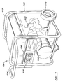
- the portable generator 100 includes an engine 102, an alternator 104, an output/control panel 106 mounted within a frame 108.
- Engine 102 provides mechanical energy for turning the alternator 104.
- engine 102 is comprised of an internal combustion engine, and may run on fuels such as gasoline, liquefied propane (LP) gas, diesel fuel, natural gas or the like.
- engine 102 may be an OHV (Overhead-Valve) engine, may utilize CIS (Cast Iron Sleeve) cylinder technology to improve its performance and useful life.
- Alternator 104 often referred to in the art as a "genhead" is coupled to the drive shaft of the engine either directly or via a belt, chain or the like, and converts the mechanical energy generated by the engine 102 into electricity.
- the output of alternator 104 is connected such that there are two 240 VAC power leads in addition to a neutral lead. This provides the user with the choice of using either 240 volts or 120 volts in any combination up to the limit of the generator 100.
- Output/control panel 106 supports electrical outlets (receptacles), circuit breakers or other circuit protection apparatus, controls (switches) for controlling the output of electrical power by the generator 100, and controls for controlling the engine 102 (e.g., an electric start switch, an idle control, an on/off switch), and the like.
- Frame 108 supports the engine 102, alternator 104 and output/control panel 106, as a portable, unitary unit that may be easily transported by the user.
- Frame 108 may also support a fuel tank 110 for providing a source of fuel for engine 102.
- fuel tank 110 is positioned above engine 102 so that fuel is supplied to the engine via a gravity feed.
- Frame 108 may further include wheels 112 and handle 114 for transport of the generator 100.
- output/control panel 106 includes a full power switch assembly 116 for allowing a user to switch off the 240 volt output in order to get more 120 volt power from the generator thereby improving the generator's ability to power larger 120 volt loads and to sustain 120 volt surge loads.
- the alternator output is reconnected so that the windings are coupled together to additively produce 120 volts while making 240 volt output unavailable.
- the full power switch assembly 116 is capable of instantly communicating the presence and operation of a full power switch to the user.
- the switch assembly 116 provides a mechanical interlock feature that requires the user to disengage a plug or plugs from any 240 volt outlets since these outlets become disabled by the switch action. In this manner, the user is forced to use the "full power" feature of the generator 100 correctly, thereby increasing the utility of the generator 100.
- the full power switch assembly 116 includes one or more outlets or receptacles 118 suitable for supplying electrical power having a first voltage.
- outlets 118 may be duplex 15 amp, 120 volt electrical outlets capable of supplying electrical power having a nominal voltage of 120 VAC.
- a second outlet or outlets 120 is positioned in the full power switch assembly 116 opposite first outlets 118 for supplying electrical power having a second voltage.
- switch assemblies 116 having a single 30 amp, 240 volt electrical outlet capable of supplying electrical power having a nominal voltage of 240 VAC are shown. Alternately, in FIGS.
- a switch assembly 116 having duplex 30 amp, 240 volt electrical outlets is shown. It is contemplated that, based on the present disclosure, those of ordinary skill in the art may now design full power switch assemblies 116 in accordance with the present invention that employ outlet configurations other than those specifically shown herein. Further, it will be appreciated that while generators providing 120/240 VAC outputs as commonly used in the United States are shown and described herein, full power switch assemblies in accordance with the present invention may be employed by generators providing outputs having other voltages such as, for example, voltages that are common in countries other than the United States (e.g., 100/200 VAC in Japan). Such full power switch assemblies and the generators in which they are employed would not depart from the scope and spirit of the present invention.
- a full power switch 122 having a selector 124 is disposed between the outlets 118 and outlet(s) 120.
- the selector 124 is movable between a first or "normal" position, shown in FIGS. 2, 4 and 6, and a second or “full power” position, shown in FIGS. 3, 5 and 7.
- the selector 124 may be finished with a bright color, and may be relatively large in size compared to outlets 118 & 120.
- full power switch 122 permits normal 120/240 volt operation of the generator 100 when selector 124 is moved to the first or "normal" position.
- selector 124 is moved to the second or “full power” position, the alternator output is reconnected so that the windings are coupled together to additively produce 120 volts while making 240 volt output unavailable.
- outlets 118 may be capable of supplying 120 volt power electrical power up to a maximum power level thereby improving the generator's ability to power larger 120 volt loads and to sustain 120 volt surge loads.
- indicia As shown in FIGS. 2 though 9, movement of the selector 124 between the first position, shown in FIGS. 2, 4, 6, and 8, and the second position, shown in FIGS. 3, 5, 7and 9, further causes indicia to be displayed for indicating whether outlets 118 are capable of supplying electrical power up to the maximum power level.
- the indicia "MOTOR START" 128 are disposed on the face of the full power switch assembly 116 so that the indicia are substantially covered by selector 124 when the selector 124 is in the first or "normal" position.
- selector 118 As selector 118 is moved to the second or “full power” position, indicia 128 are uncovered so that they are viewable by a user of the generator 100.
- indicia 128 displayed by full power switch assembly 116 when selector 124 is moved to the second or “full power” position are not limited to the words "MOTOR START" shown in FIGS. 2 through 9, but instead may include any word, phrase, symbol, or the like suitable for providing an indication to the user as to whether outlets 118 are capable of supplying electrical power up to the maximum power level.
- embodiments of the present invention may utilize phrases such as "MAXIMUM POWER", “MAX POWER”, “FULL POWER”, an iconic symbol or symbols, or the like without departing from the scope and spirit of the present invention.
- selector 124 includes a mechanical interlock 126 for preventing a plug from being received by outlet(s) 120 when selector 124 is in or near the second or "full power" position shown in FIGS. 3, 5, 7 and 9.
- the mechanical interlock 126 requires the user to disengage and remove a plug previously inserted in outlet(s) 120 before full power is selected since outlet(s) 120 (240 VAC power) becomes at least partially disabled by the switch action. If "normal" 240 volt power is thereafter required, selector 124 again moved to the first position causing outlet(s) 120 to become available to receive a 240 volt plug.
- FIGS. 2 through 9 movement of selector 124 between the first and second positions may be accomplished in variety of ways.
- FIGS. 2 and 3 illustrate a full power switch assembly 116 employing a rocker switch or slide switch, wherein selector 124 slides between the first position and the second position.
- mechanical interlock 126 is slid over at least a portion of outlet 120 to prevent the outlet 120 from receiving a 240 volt plug.
- power switch assembly 116 may employ a rotary switch so that the selector rotates between the first position and the second position and mechanical interlock 126 is likewise rotated over at least a portion of outlet 120.
- power switch assembly 116 may utilize a toggle switch such that the selector 124 pivots between the first position and the second position partially covering outlet 120 to provide mechanical interlock 126.
- FIGS. 8 and 9 illustrate a full power switch assembly 116 employing a slide switch and duplex 120 VAC and 240 VAC outlets, wherein selector 124 slides between the first position and the second position. It will be appreciated that, in embodiments of the invention, the full power switch assembly 116 shown in FIGS. 8 and 9 may alternately employ the rotary or toggle switches of the switch assembly embodiments shown in FIGS.4 through 7, thus providing a selector 124 having an interlock 126 that either rotates or pivots to at least partially cover outlets 120.
- full power switch assembly 116 may be biased to the full power position.
- selector 124 may be spring biased to the second position wherein mechanical interlock 126 is slid over at least a portion of outlet 120 to prevent the outlet 120 from receiving a 240 volt plug. In this manner, the generator 100 is forced to operate in the full power mode (120 VAC output only) unless the user purposefully switches it to the normal mode (both 120 and 240 VAC output).
Landscapes
- Engineering & Computer Science (AREA)
- Chemical & Material Sciences (AREA)
- Combustion & Propulsion (AREA)
- Mechanical Engineering (AREA)
- General Engineering & Computer Science (AREA)
- Control Of Eletrric Generators (AREA)
- Details Of Connecting Devices For Male And Female Coupling (AREA)
Abstract
Description
Claims (25)
- A full power switch assembly (116) for a generator (100), characterized by:wherein movement of the selector (124) between the first position and the second position further causes indicia (128) to be displayed for indicating whether the first outlet (118) is capable of supplying electrical power up to the maximum power level.a first outlet (118) for supplying electrical power having a first voltage;a second outlet (120) for supplying electrical power having a second voltage; anda switch (122) including a selector (124) movable between a first position and a second position, the switch (122) being suitable for causing the first outlet (118) to be capable of supplying electrical power up to a maximum power level when the selector (124) is moved to the second position,
- The full power switch assembly (116) as claimed in claim 1, wherein the selector (124) includes a mechanical interlock (126) for preventing a plug from being received by the second outlet (120) when the selector (124) is in the second position.
- The full power switch assembly (116) as claimed in claims 1 or 2, wherein the switch (122) comprises one of a rocker switch and a slide switch, and wherein the selector (124) slides between the first position and the second position.
- The full power switch assembly (116) as claimed in claims 1 or 2, wherein the switch (122) comprises a rotary switch, and wherein the selector (124) rotates between the first position and the second position.
- The full power switch assembly (116) as claimed in claims 1 or 2, wherein the switch (122) comprises a toggle switch, and wherein the selector (124) pivots between the first position and the second position.
- The full power switch assembly (116) as claimed in any of claims 1 through 5, wherein the first voltage is approximately 120 VAC and the second voltage is approximately 240 VAC.
- The full power switch assembly (116) as claimed in any of claims 1 through 6, wherein the selector is biased to the second position.
- A full power switch assembly (116) for a generator (100), characterized by:a first outlet (118) for supplying electrical power having a first voltage;a second outlet (120) for supplying electrical power having a second voltage;a switch (122) including a selector (124) movable between a first position and a second position, the switch (122) being suitable for causing the first outlet (118) to be capable of supplying electrical power up to a maximum power level when the selector (124) is moved to the second position; anda mechanical interlock (126) coupled to the selector (124) for preventing a plug from being received by the second outlet (120) when the selector (124) is in the second position.
- The full power switch assembly (116) as claimed in claim 8, wherein movement of the selector (124) between the first position and the second position causes indicia (128) to be displayed for indicating whether the first outlet (118) is capable of supplying electrical power up to the maximum power level.
- The full power switch assembly (116) as claimed in claims 8 or 9, wherein the switch (122) comprises one of a rocker switch and a slide switch, and wherein the selector (124) slides between the first position and the second position.
- The full power switch assembly (116) as claimed in claims 8 or 9, wherein the switch (122) comprises a rotary switch, and wherein the selector (124) rotates between the first position and the second position.
- The full power switch assembly (116) as claimed in claims 8 or 9, wherein the switch (122) comprises a toggle switch, and wherein the selector (124) pivots between the first position and the second position.
- The full power switch assembly (116) as claimed in any of claim 8 through 12, wherein the first voltage is approximately 120 VAC and the second voltage is approximately 240 VAC.
- The full power switch assembly (116) as claimed in any of claims 8 through 13, wherein the selector (124) is biased to the second position.
- A generator (100), characterized by:wherein movement of the selector (124) between the first position and the second position exposes indicia (128) for indicating whether the first outlet (118) is capable of supplying electrical power up to the maximum power level.an alternator (104) capable of generating electrical power from mechanical power;an engine (102) for providing mechanical power to the alternator (104); anda first outlet (118) for supplying the electrical power generated by the alternator (104) at a first voltage;a second outlet (120) for supplying electrical power generated by the alternator (104) at a second voltage; anda switch (122) including a selector (124) movable between a first position and a second position, the switch being suitable for switching off the electrical power supplied by the second outlet (120) and causing the first outlet (122) to be capable of supplying electrical power up to a maximum power level when the selector (124) is moved to the second position,
- The generator (100) as claimed in claim 15, wherein the selector (124) includes a mechanical interlock (126) for preventing a plug from being received by the second outlet (120) when the selector (124) is in the second position.
- The generator (100) as claimed in claims 15 or 16, wherein the switch (122) comprises one of a rocker switch and a slide switch, and wherein the selector (124) slides between the first position and the second position.
- The generator (100) as claimed in claims 15 or 16, wherein the switch (122) comprises a rotary switch, and wherein the selector (124) rotates between the first position and the second position.
- The generator (100) as claimed in claim 15, wherein the switch (122) comprises a toggle switch, and wherein the selector (124) pivots between the first position and the second position.
- The generator (100) as claimed in any of claims 15 through 19, wherein the selector (124) is biased to the second position.
- A generator (100), characterized by:wherein movement of the selector (124) between the first position and the second position exposes indicia (128) for indicating whether the first outlet (118) is capable of supplying electrical power up to the first or second maximum power levels and prevents a plug from being received by the second outlet (120) when the selector (124) is in the second position.an alternator (104) capable of generating electrical power from mechanical power;an engine (102) for providing mechanical power to the alternator (104); anda first outlet (118) for supplying the electrical power generated by the alternator (104) at a first voltage;a second outlet (120) for supplying electrical power generated by the alternator (104) at a second voltage; anda switch (122) including a selector (124) movable between a first position and a second position, the switch (122) being suitable for causing the first outlet (118) to be capable of supplying electrical power up to a first maximum power level when the selector (124) is moved to the first position, and to be capable of supplying electrical power up to a second maximum power level when the selector (124) is moved to the second position by switching off the electrical power supplied by the second outlet (120),
- The generator (100) as claimed in claim 21, wherein the switch (122) comprises one of a rocker switch and a slide switch, and wherein the selector (124) slides between the first position and the second position.
- The generator (100) as claimed in claim 21, wherein the switch (122) comprises a rotary switch, and wherein the selector (124) rotates between the first position and the second position.
- The generator (100) as claimed in claim 21, wherein the switch (122) comprises a toggle switch, and wherein the selector (124) pivots between the first position and the second position.
- The generator (100) as claimed in any of claims 21 through 24, wherein the selector (124) is biased to the second position.
Applications Claiming Priority (2)
| Application Number | Priority Date | Filing Date | Title |
|---|---|---|---|
| US834458 | 1992-02-12 | ||
| US09/834,458 US6541718B2 (en) | 2001-03-07 | 2001-04-13 | Full power switch assembly for portable generators |
Publications (2)
| Publication Number | Publication Date |
|---|---|
| EP1249900A2 true EP1249900A2 (en) | 2002-10-16 |
| EP1249900A3 EP1249900A3 (en) | 2003-11-19 |
Family
ID=25266990
Family Applications (1)
| Application Number | Title | Priority Date | Filing Date |
|---|---|---|---|
| EP02251498A Withdrawn EP1249900A3 (en) | 2001-04-13 | 2002-03-04 | Full power switch assembly for portable generators |
Country Status (1)
| Country | Link |
|---|---|
| EP (1) | EP1249900A3 (en) |
Family Cites Families (7)
| Publication number | Priority date | Publication date | Assignee | Title |
|---|---|---|---|---|
| GB454172A (en) * | 1935-04-13 | 1936-09-25 | Wm Sanders & Co Wednesbury Ltd | Improvements in and relating to three pin plug-in electric switches |
| DE890368C (en) * | 1951-05-24 | 1953-09-17 | Siemens Ag | Contact device of a crossbar distributor for a battery charging or discharging circuit |
| JPS5857090U (en) * | 1981-10-14 | 1983-04-18 | 星電器製造株式会社 | power socket |
| US4738629A (en) * | 1985-05-07 | 1988-04-19 | Rotaflex Plc | Electric sockets |
| US5301494A (en) * | 1992-07-24 | 1994-04-12 | Ryobi Motor Products Corp. | Recharging system for a battery operated tool having an on-board transformer |
| US5577923A (en) * | 1994-12-12 | 1996-11-26 | Lee; Chiu-Shan | 125V/250V safety electric socket devices |
| US6084313A (en) * | 1998-08-13 | 2000-07-04 | Coleman Powermate, Inc. | Generator system with vertically shafted engine |
-
2002
- 2002-03-04 EP EP02251498A patent/EP1249900A3/en not_active Withdrawn
Also Published As
| Publication number | Publication date |
|---|---|
| EP1249900A3 (en) | 2003-11-19 |
Similar Documents
| Publication | Publication Date | Title |
|---|---|---|
| US6541718B2 (en) | Full power switch assembly for portable generators | |
| US12142930B2 (en) | Portable hybrid generator | |
| US11143145B2 (en) | Batteryless dual fuel engine with liquid fuel cut-off | |
| US8643238B2 (en) | Intelligent cascaded synchronous electric motor-generator tandems of cumulative compound excitation | |
| US20100319646A1 (en) | Combustion and emergency starting control system with auxiliary power | |
| US8667942B2 (en) | Split-type auxiliary power combustion and emergency starting system | |
| MY128623A (en) | Power supplying apparatus for vehicle | |
| US20190173353A1 (en) | Motor programming tool | |
| EP1249900A2 (en) | Full power switch assembly for portable generators | |
| US6684839B2 (en) | Ignition or fuel injection control system with auxiliary source | |
| WO2002091562A1 (en) | Portable generator for communications systems | |
| JP4960141B2 (en) | Emergency operation power supply | |
| US7325524B2 (en) | Ignition/fuel injection system with auxiliary and separation charging power sources | |
| CA2402192A1 (en) | A fuel cell powered torque motor | |
| US11631990B2 (en) | Power supply connection device | |
| US7320601B1 (en) | Power storage structure | |
| US20070251469A1 (en) | Cogeneration Apparatus | |
| JP4330001B2 (en) | Engine generator | |
| CN217682060U (en) | Engine ignition key and engine start control circuit | |
| KR102661183B1 (en) | engine starting control device | |
| JP3568796B2 (en) | Power supply | |
| US20250334093A1 (en) | Emergency fuel shutoff battery for gas powered generator | |
| US20250320837A1 (en) | Dual fuel system with electric battery for power generation | |
| IL100659A (en) | Electric power source for car | |
| BE1013020A6 (en) | Energy generator block for electric vehicle. |
Legal Events
| Date | Code | Title | Description |
|---|---|---|---|
| PUAI | Public reference made under article 153(3) epc to a published international application that has entered the european phase |
Free format text: ORIGINAL CODE: 0009012 |
|
| AK | Designated contracting states |
Kind code of ref document: A2 Designated state(s): AT BE CH CY DE DK ES FI FR GB GR IE IT LI LU MC NL PT SE TR |
|
| AX | Request for extension of the european patent |
Free format text: AL;LT;LV;MK;RO;SI |
|
| PUAL | Search report despatched |
Free format text: ORIGINAL CODE: 0009013 |
|
| AK | Designated contracting states |
Kind code of ref document: A3 Designated state(s): AT BE CH CY DE DK ES FI FR GB GR IE IT LI LU MC NL PT SE TR |
|
| AX | Request for extension of the european patent |
Extension state: AL LT LV MK RO SI |
|
| RIC1 | Information provided on ipc code assigned before grant |
Ipc: 7H 01R 13/707 B Ipc: 7H 01R 13/453 B Ipc: 7H 01R 29/00 A |
|
| AKX | Designation fees paid | ||
| REG | Reference to a national code |
Ref country code: DE Ref legal event code: 8566 |
|
| STAA | Information on the status of an ep patent application or granted ep patent |
Free format text: STATUS: THE APPLICATION IS DEEMED TO BE WITHDRAWN |
|
| 18D | Application deemed to be withdrawn |
Effective date: 20040520 |