EP1249833A2 - Optical disk with area for recognising individual disks - Google Patents
Optical disk with area for recognising individual disks Download PDFInfo
- Publication number
- EP1249833A2 EP1249833A2 EP20020008156 EP02008156A EP1249833A2 EP 1249833 A2 EP1249833 A2 EP 1249833A2 EP 20020008156 EP20020008156 EP 20020008156 EP 02008156 A EP02008156 A EP 02008156A EP 1249833 A2 EP1249833 A2 EP 1249833A2
- Authority
- EP
- European Patent Office
- Prior art keywords
- optical disk
- area
- information
- substrate
- main
- Prior art date
- Legal status (The legal status is an assumption and is not a legal conclusion. Google has not performed a legal analysis and makes no representation as to the accuracy of the status listed.)
- Ceased
Links
Images

Classifications
-
- G—PHYSICS
- G11—INFORMATION STORAGE
- G11B—INFORMATION STORAGE BASED ON RELATIVE MOVEMENT BETWEEN RECORD CARRIER AND TRANSDUCER
- G11B7/00—Recording or reproducing by optical means, e.g. recording using a thermal beam of optical radiation by modifying optical properties or the physical structure, reproducing using an optical beam at lower power by sensing optical properties; Record carriers therefor
- G11B7/007—Arrangement of the information on the record carrier, e.g. form of tracks, actual track shape, e.g. wobbled, or cross-section, e.g. v-shaped; Sequential information structures, e.g. sectoring or header formats within a track
- G11B7/00736—Auxiliary data, e.g. lead-in, lead-out, Power Calibration Area [PCA], Burst Cutting Area [BCA], control information
-
- G—PHYSICS
- G11—INFORMATION STORAGE
- G11B—INFORMATION STORAGE BASED ON RELATIVE MOVEMENT BETWEEN RECORD CARRIER AND TRANSDUCER
- G11B19/00—Driving, starting, stopping record carriers not specifically of filamentary or web form, or of supports therefor; Control thereof; Control of operating function ; Driving both disc and head
- G11B19/02—Control of operating function, e.g. switching from recording to reproducing
- G11B19/12—Control of operating function, e.g. switching from recording to reproducing by sensing distinguishing features of or on records, e.g. diameter end mark
- G11B19/122—Control of operating function, e.g. switching from recording to reproducing by sensing distinguishing features of or on records, e.g. diameter end mark involving the detection of an identification or authentication mark
-
- G—PHYSICS
- G11—INFORMATION STORAGE
- G11B—INFORMATION STORAGE BASED ON RELATIVE MOVEMENT BETWEEN RECORD CARRIER AND TRANSDUCER
- G11B20/00—Signal processing not specific to the method of recording or reproducing; Circuits therefor
- G11B20/00086—Circuits for prevention of unauthorised reproduction or copying, e.g. piracy
-
- G—PHYSICS
- G11—INFORMATION STORAGE
- G11B—INFORMATION STORAGE BASED ON RELATIVE MOVEMENT BETWEEN RECORD CARRIER AND TRANSDUCER
- G11B23/00—Record carriers not specific to the method of recording or reproducing; Accessories, e.g. containers, specially adapted for co-operation with the recording or reproducing apparatus ; Intermediate mediums; Apparatus or processes specially adapted for their manufacture
- G11B23/28—Indicating or preventing prior or unauthorised use, e.g. cassettes with sealing or locking means, write-protect devices for discs
- G11B23/281—Indicating or preventing prior or unauthorised use, e.g. cassettes with sealing or locking means, write-protect devices for discs by changing the physical properties of the record carrier
-
- G—PHYSICS
- G11—INFORMATION STORAGE
- G11B—INFORMATION STORAGE BASED ON RELATIVE MOVEMENT BETWEEN RECORD CARRIER AND TRANSDUCER
- G11B23/00—Record carriers not specific to the method of recording or reproducing; Accessories, e.g. containers, specially adapted for co-operation with the recording or reproducing apparatus ; Intermediate mediums; Apparatus or processes specially adapted for their manufacture
- G11B23/38—Visual features other than those contained in record tracks or represented by sprocket holes the visual signals being auxiliary signals
-
- G—PHYSICS
- G11—INFORMATION STORAGE
- G11B—INFORMATION STORAGE BASED ON RELATIVE MOVEMENT BETWEEN RECORD CARRIER AND TRANSDUCER
- G11B7/00—Recording or reproducing by optical means, e.g. recording using a thermal beam of optical radiation by modifying optical properties or the physical structure, reproducing using an optical beam at lower power by sensing optical properties; Record carriers therefor
- G11B7/24—Record carriers characterised by shape, structure or physical properties, or by the selection of the material
- G11B7/2403—Layers; Shape, structure or physical properties thereof
- G11B7/24035—Recording layers
- G11B7/24038—Multiple laminated recording layers
-
- G—PHYSICS
- G11—INFORMATION STORAGE
- G11B—INFORMATION STORAGE BASED ON RELATIVE MOVEMENT BETWEEN RECORD CARRIER AND TRANSDUCER
- G11B7/00—Recording or reproducing by optical means, e.g. recording using a thermal beam of optical radiation by modifying optical properties or the physical structure, reproducing using an optical beam at lower power by sensing optical properties; Record carriers therefor
- G11B7/24—Record carriers characterised by shape, structure or physical properties, or by the selection of the material
- G11B7/26—Apparatus or processes specially adapted for the manufacture of record carriers
Definitions
- the present invention relates to an optical disk which is formed by adhering two surfaces for forming information to an adhesive layer. More particularly, the present invention relates to an optical disk having an individual recognizing function, which can be managed as a product easily and effectively and in which the falsification can be prevented.
- Distribution media such as an optical disk are widely used due to the large capacity and the low cost for forming pits.
- various applications are proposed with a CD (Compact Disk) and a DVD (Digital Video Disk) by using the large capacity thereof.
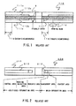
- an optical disk 110 is used as an optical disk having the above-mentioned individual recognizing function according to the related art.
- the optical disk 110 is formed by adhering to an adhesive layer 3, surfaces having aluminum film forming areas 112a and 112b made of thin aluminum films on two ring disk-shaped polycarbonate substrates 111a and 111b.
- Main information is recorded to the aluminum film forming areas 112a and 112b by using laser beams or the like.
- the main information is read by radiating reading beams which are condensed by a condenser lens 115.
- a management identifier area 117 of an optical disk lot is provided at a center-side peripheral of the aluminum film forming area 112b to which the main information is recorded, on an inner-circumference portion 118 of the ring disk-shaped polycarbonate substrate 111b.
- Management information such as title, order name, and lot number is recorded to the management identifier area 117 by printing.
- linear information upon exposure is recorded to the corresponding area such as a number, a character, and a barcode upon exposing an optical disk stamper, as surface information which can visually be recognized in general.
- a CCD camera or the like identifies and manages the management information. Consequently, it is advantageous to prevent trouble such as the mixing of foreign materials by identifying the above management information.
- the optical disk 200 has a main-information area 212 and an additional-information area 213 in a substrate 211 thereof.
- the additional-information area 213 has an area for inhibiting the reading of the recorded data and a control area indicating whether information on the prohibition of reading is present or absent.
- a reading device of the optical disk 200 does not externally output the information on the prohibition of reading and, therefore, the information on the prohibition of reading is not downloaded when information except therefor is downloaded.
- the information on the prohibition of reading includes a cipher key for the main information, thereby preventing the normal reading of cipher data which is downloaded. If the information on the prohibition of reading might be read, a manufacturer can find an illegal source by including management information such as an order side in the information on the prohibition of reading.
- the optical disk having the conventional individual recognizing function has a problem to erroneously operate the optical disk to which data to be downloaded excluding the main information is recorded.
- the management information on each optical disk is not subjected to a specific countermeasure.
- the optical disk records the management information such as the title, the order-side name, and the lot identification Information.
- the management information such as the title, the order-side name, and the lot identification Information.
- a management number for each customer is additionally input to the above-described management information.
- each optical disk is not subjected to detailed management Therefore, an optical disk having another management information might erroneously be operated by inputting the management number of any customer.
- an object of the present invention to provide an optical disk having an individual recognizing function for effectively managing each optical disk, which is suitable to product management for easily inhibiting the illegal use of manufactured and sold optical disks.
- an optical disk having an individual recognizing function and a ring disk-shaped body comprising a first substrate having a first principal surface, a second substrate having a second principal surface, an adhesive layer, principally.
- the adhesive layer is sandwiched between the first principal surface of the first substrate and the second principle surface of the second substrate and to which the first substrate and the second substrate are adhered.
- at least one of the first principal surface and the second principal surface has an individual recognizing area.
- identification information for uniquely recognizing the optical disk is recorded before adhering the first substrate and the second substrate.
- the individual recognizing area is placed to at least one of an inner-circumference portion and an outer-circumference portion adjacent to the main-information area on the substrate. This position exists when the optical disk is perspectively viewed in the vertical direction of the first principal surface and the second principal surface.
- the identification information can be read but cannot be recorded and changed by using the laser beams used for recording or reading the main information to the main-information area.
- the optical disk in the present invention is formed by adhesion of at least two surfaces used for forming information to the adhesive layer.
- the optical disk has the individual recognizing area for read only.
- the individual recognizing area is placed to at least one of an inner-circumference portion and an outer-circumference portion adjacent to the main-information area on the substrate for recording the main information to one of the adhering surfaces.
- the identification information for uniquely recognizing the optical disk is recorded.
- the identification information for each optical disk can be uniquely read from the individual recognizing area on the optical disk by using, e.g., the reading beams. Therefore, the downloading destination can certainly be confirmed. It is possible to read the recorded main information by only the reading device having identification information which completely matches the above-described identification information for each optical disk.
- the security can be highly ensured by using the management and the identification of each optical disk. Not only by inputting a password but also by combining the identification of the optical disk and the password, a user is determined or authenticated. Simultaneously, the optical disk can safely be used while highly maintaining the confidentiality of data.
- the above-described identification information may be recorded and formed by printing a pattern having a predetermined difference in tint at the individual recognizing area.
- the printed identification information can be read by the reading beams and, further, can visually be recognized by the difference in tint. Therefore, upon loading, the optical disk can be identified and can be checked in advance.
- the pattern having the predetermined difference in tint may be at least one of a character, a number, a barcode, and a drawing.
- the printing may be any of screen printing, ink-jet printing, offset printing, and ink stamp.
- the identification information for each optical disk is recorded to the individual recognizing area on the substrate surface which is adhered to the adhesive layer by the printing so as to prevent the easy falsification of the optical disk.
- the optical disk must be broken to change the data of the optical disk on purpose. Therefore, the above-described structure becomes safe against the falsification.
- the above-described individual recognizing area may be adjacent to a management area which is provided at a circumference portion of the main-information area. Further, the individual recognizing area can function as a part of the management area.
- the optical disk may comprise an individual recognizing area for read only on one of the adhering surfaces and a film forming area on the other of the adhering surfaces.
- identification information for uniquely recognizing the optical disk is recorded to at least one of an inner-circumference portion and an outer-circumference portion adjacent to a main-information area for recording main information on the surfaces.
- the film forming area is used for covering the individual recognizing area.
- the film forming area for covering the individual recognizing area may be formed as a part of the main-information area.
- the film forming area is total reflection or half-transparent, and reaches the back of a reading-beam irradiated surface of the individual recognizing area. Therefore, it is possible to identify with a higher recognizing ratio and with high contrast, the recorded contents having the difference in tint. In particular, advantageously, information such as a printed mark is visually checked.
- the product management of the optical disk can easily be performed.
- the printing enables the area whose tint can visually be identified, including the character, the number, the barcode, the drawing, etc. to be formed at an area other than the main-information area. Further, the security can effectively be assured by recognizing and collating the formed area with the reading beams or combining the formed area and a specific password after the recognition and collation.
- the optical disk cannot be falsified.
- the area capable of identifying each optical disk can be formed by the printing before adhesion of substrates.
- the data at the formed area of the completed optical disk cannot be falsified. If performing such a falsification that the adhesion of the substrates in the optical disk is peered and new data is recorded, the polycarbonate (PC) substrate is broken or mechanical characteristics are extremely deteriorated because the strength of adhesion is high. The reading of the optical disk becomes impossible. Actually, the optical disk becomes unavailable.
- PC polycarbonate
- Fig. 3 is a cross-sectional view schematically showing the structure of an optical disk according to a first embodiment of the present invention.
- an optical disk 10 having a ring and disk-shaped form comprises main-information areas 12a and 12b and an individual recognizing area 4a on adhesive surfaces of substrates 11a and 11b made of two ring disk-shaped polycarbonate (PC) substrates which are adhered to an adhesive layer 3.
- the optical disk 10 has the individual recognizing area 4a.
- the optical disk 10 is formed by adhesion of the surfaces of the substrates 11a and 11b to the adhesive layer 3 in the center. Reading beams are incident from the substrate 11b side shown in the lower side in the Fig. 3 via a condenser lens 15 and pits on a recording film or on an information area are formed on an inner surface near the incident surface.
- the adhesive surfaces of the substrates 11a and 11b include the main-information areas 12a and 12b as film forming areas to which main information is recorded and the individual recognizing area 4a.
- Each of the main-information areas 12a and 12b comprises a contents area to which data contents are recorded and a management area having a control table (TOC), for managing the content area.
- TOC control table
- the main-information areas 12a and 12b as the film forming areas to which the main information is recorded correspond to reflecting films.
- the main-information area 12b is a half-transparent film made of e.g., aluminum and the main-information area 12a is a total-reflecting film.
- the adhesive layer 3 is made of UV cure adhesive, slow-cure resin, hot-melt resin, etc., depending on a reading system such as one layer for reading on one side, or two layers for reading on one side.
- the individual recognizing area 4a as the feature of the present invention is provided for an inner-circumference portion 18 adjacent to the management area of the main-information area 12a.
- printing e.g., screen printing, ink-jet printing, offset printing, and ink stamp
- the individual recognizing area 4a is formed during processing for manufacturing the optical disk 10 before the adhesion of the substrates. Therefore, the optical disk cannot be falsified by using a strong adhesive.
- the condenser lens 15 of a reading device is an objective lens for used for condensing the reading beams and performs focusing servo and tracking servo by using itself. Simultaneously, the main-information areas 12a and 12b are read by the reading beams. Incidentally, a management identifier of the individual recognizing area 4a can be read by using the reading beams. According to the first embodiment, the reading device reads the management identifier of the individual recognizing area 4a by using the reading beams and collates the read management identifier with the identifier in the reading device. And the reading device reads the main-information areas 12a and 12b by using the reading beams only when the read management identifier matches the identifier in the reading device. Further, according to the first embodiment, in the optical disk having the two layers for reading on one side, a common management-identifier can be read in a first layer and a second layer.
- the individual recognizing area 4a such as a character, a number, a barcode, a drawing, and a tint which can be visually recognized, by printing, e.g., screen printing, ink-jet printing, offset printing, and ink stamp.
- printing e.g., screen printing, ink-jet printing, offset printing, and ink stamp.
- the optical disk manufactured in the above processing is formed an area which can visually be identified, e.g., a character, a number, a barcode, a drawing, or a tint, before the adhesion of the substrates.
- the area is formed by using of printing such as screen printing, ink-jet printing, offset printing, or ink stamp. Therefore, data on the area in the completed optical disk cannot be falsified. If performing such a falsification that the adhesion of the substrates in the optical disk is peered and new data is recorded, the optical disk is broken or mechanical characteristics are extremely deteriorated because the strength of adhesion is high. The reading becomes impossible. Actually, the optical disk becomes unavailable.
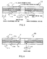
- Fig. 4 is a cross-sectional view for explaining the structure of the optical disk 20 according to a second embodiment of the present invention.
- the structure shown in Fig. 4 is modifying that shown in Fig. 3.
- an individual recognizing area 4b in Fig. 4 is formed to a substrate 21b instead of the substrate 11b shown in Fig. 3 on the incident surface.
- Other components are the same as those in Fig. 5, and reference numerals 10, 11a, 11b, 12a, 12b, and 15 may be replaced with reference numerals 20, 21 a, 21b, 22a, 22b, and 25.
- the optical disk 20 is formed by adhesion of two ring disk-shaped substrates 21a and 21b to an adhesive layer 3 in the center. Reading beams are incident from the substrate 21b side shown in the lower side in the Fig. 4 via a condenser lens 25 and pits on a recording film or on an information area are formed on the inner surface near an incident surface.
- Main-information areas 22a and 22b correspond to film forming areas to which main information is formed.
- the individual recognizing area 4b is provided at an inner-circumference portion adjacent to the main-information area 22b.
- printing e.g., screen printing, ink-jet printing, offset printing, and ink stamp
- the individual recognizing area 4a is formed during manufacturing processing before the adhesion of the substrates 21a and 21b in the optical disk 20.
- Fig. 5 is a cross-sectional view for explaining the structure of the optical disk 30 according to a third embodiment of the present invention.
- the structure shown in Fig. 5 is modifying that shown in Fig. 4.
- a main-information area 32a on a substrate 31a side is formed to reach the backside of the individual recognizing area 4b where is an inner-circumference portion of the substrate wider than a main-information area 32b provided for a substrate 31b.
- the individual recognizing area 4b is recorded by the printing such as the screen printing, the ink-jet printing, the offset printing, or the ink stamp.
- the above-described structure becomes effective when information such as a printed mark is visually checked.
- the optical disk 30 is formed by adhesion of the two ring disk-shaped substrates 31a and 31b to an adhesive layer 3 in the center. Reading beams are incident from the substrate 31b side shown in the lower side in Fig. 5 via a condenser lens 35 and pits on a recording film or on an information area are formed on an inner surface near the incident surface.
- Main-information areas 32a and 32b correspond to film forming areas to which main information is formed.
- the individual recognizing area 4b is provided at an inner-circumference portion of the substrate 31b adjacent to the main-information area 32b, within the range of the main-information area 32a.
- Fig. 6 is a cross-sectional view for explaining the structure of the optical disk 40 according to a fourth embodiment of the present invention.
- the structure shown in Fig. 6 is modifying that shown in Fig. 3.
- an individual recognizing area 44 on a substrate 41b side shown in Fig. 6 is formed at an outer-circumference portion adjacent to a main-information area 42a on a substrate 41a.
- Other components are the same as those in Fig. 3 and reference numerals 10, 11a, 11b, 12a, 12b, and 15 may be replaced with reference numerals 40, 41a, 41b, 42a, 42b, and 45.
- the optical disk 40 is formed by adhesion of the two ring disk-shaped substrates 41a and 41b to an adhesive layer 3 in the center. Reading beams are incident from the substrate 41b side shown in the lower side in the Fig. 6 via a condenser lens 45 and pits on a recording film or on an information area are formed on an inner surface near the incident surface.
- Main-information areas 42a and 42b correspond to film forming areas to which main information is formed.
- the individual recognizing area 44 is provided at an outer-circumference portion adjacent to the main-information area 42a on the substrate 41a.
- printing e.g., screen printing, ink-jet printing, offset printing, and ink stamp, it is possible to record to the individual recognizing area 44, visually recognized data for each optical disk such as a character, a number, a barcode, a drawing, and tint.
- the individual recognizing area 44 is formed during manufacturing processing before the adhesion of the substrates 41a and 41b in the optical disk 40.
- the management area of the optical disk is not necessarily limited to the inner- circumference portion. That is, in the case of the optical disk having the two layers for reading on one side, the management area can be formed at an outer-circumference portion relative to a middle area.
- the middle area is formed when a first layer (L0) and a second layer (L1) on the incident surface side are sequentially read (oppositely read).
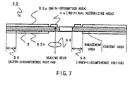
- an optical disk 50 comprises surfaces 52a and 52b and an individual recognizing area 4a on an adhesive layer 3. Unlike the optical disks mentioned above, the optical disk 50 has not any substrate.
- the optical disk 50 is formed by adhesion of the surfaces 52a and 52b to the adhesive layer 3 in the center.
- the other portions are the same as one shown in Fig. 3.
- the surfaces 52a and 52b are the main-information areas as film forming areas to which main information is recorded.
- the individual recognizing area 4a as the feature of the present invention is provided for an inner-circumference portion 58 adjacent to the management area of the main-information area 52a.
- the optical disk having no adhesion of the substrates such as a CD-ROM, as compared with the above-described management for each optical disk before the adhesion of the substrates, the security against the data falsification is not so higher.
- the optical disk can similarly be formed by use of specific ink or the like.
- UV cure adhesive can be applied after forming the above-described management area at the inner-circumference portion or the outer-circumference portion of the data area.
- a system comprising the above-mentioned optical disk and a reading device.
- the reading device reads the identification information on the individual recognizing area on the optical disk by using the laser beams.
- the reading device checks to see if the read identification information on the optical disk matches the identification information in the reading device.
- the reading device reads the main information on the main-information area on the optical disk only when the identification information on the optical disk matches the identification information therein.
Landscapes
- Engineering & Computer Science (AREA)
- Computer Security & Cryptography (AREA)
- Manufacturing & Machinery (AREA)
- Signal Processing (AREA)
- Optical Record Carriers And Manufacture Thereof (AREA)
- Optical Recording Or Reproduction (AREA)
- Signal Processing For Digital Recording And Reproducing (AREA)
Abstract
Description
- The present invention relates to an optical disk which is formed by adhering two surfaces for forming information to an adhesive layer. More particularly, the present invention relates to an optical disk having an individual recognizing function, which can be managed as a product easily and effectively and in which the falsification can be prevented.
- Distribution media such as an optical disk are widely used due to the large capacity and the low cost for forming pits. In particular, various applications are proposed with a CD (Compact Disk) and a DVD (Digital Video Disk) by using the large capacity thereof.
- In accordance with the large capacity for storing data in the optical disk, a variety of copy managements are proposed so as to prevent an easy copy. However, hacking causes heavy damage to copy managements all over the world.
- Under such a situation, data is recognized every disk and an illegal copy is prevented. Further, the management for each optical disk is regarded as important for improving the protection of contents, the higher copy management, and the security.
- Referring to Fig. 1, an
optical disk 110 is used as an optical disk having the above-mentioned individual recognizing function according to the related art. Theoptical disk 110 is formed by adhering to anadhesive layer 3, surfaces having aluminum film forming areas 112a and 112b made of thin aluminum films on two ring disk-shaped polycarbonate substrates 111a and 111b. Main information is recorded to the aluminum film forming areas 112a and 112b by using laser beams or the like. The main information is read by radiating reading beams which are condensed by a condenser lens 115. - As shown in Fig. 1, a
management identifier area 117 of an optical disk lot is provided at a center-side peripheral of the aluminum film forming area 112b to which the main information is recorded, on an inner-circumference portion 118 of the ring disk-shaped polycarbonate substrate 111b. Management information such as title, order name, and lot number is recorded to themanagement identifier area 117 by printing. In the case of the above recording, linear information upon exposure is recorded to the corresponding area such as a number, a character, and a barcode upon exposing an optical disk stamper, as surface information which can visually be recognized in general. In the manufacturing after exposing the optical disk stamper, a CCD camera or the like identifies and manages the management information. Consequently, it is advantageous to prevent trouble such as the mixing of foreign materials by identifying the above management information. - Further, as disclosed in Japanese Unexamined Patent Application Publication No. 2000-163883, main information is recorded to an optical disk. Additional-information area data is also recorded to the optical disk. In the above-described optical disk, effectively, the copyright of contents is protected and illegal software operation is prevented.
- Referring to Fig. 2, an optical disk disclosed in the above Publication will be described in followings. The
optical disk 200 has a main-information area 212 and an additional-information area 213 in a substrate 211 thereof. The additional-information area 213 has an area for inhibiting the reading of the recorded data and a control area indicating whether information on the prohibition of reading is present or absent. A reading device of theoptical disk 200 does not externally output the information on the prohibition of reading and, therefore, the information on the prohibition of reading is not downloaded when information except therefor is downloaded. As a consequence, the information on the prohibition of reading includes a cipher key for the main information, thereby preventing the normal reading of cipher data which is downloaded. If the information on the prohibition of reading might be read, a manufacturer can find an illegal source by including management information such as an order side in the information on the prohibition of reading. - The optical disk having the conventional individual recognizing function has a problem to erroneously operate the optical disk to which data to be downloaded excluding the main information is recorded.
- The management information on each optical disk is not subjected to a specific countermeasure.
- In the related art shown in Fig. 1, the optical disk records the management information such as the title, the order-side name, and the lot identification Information. In the case that high-priced data contents are installed in a CD-ROM, a management number for each customer is additionally input to the above-described management information. However, actually, each optical disk is not subjected to detailed management Therefore, an optical disk having another management information might erroneously be operated by inputting the management number of any customer.
- In the related art shown in Fig. 2, although the illegal copy and the falsification of the recorded contents are prevented, the management measurement against the downloading of information to an erroneous area is not adopted.
- To solve the above-described problems, it is an object of the present invention to provide an optical disk having an individual recognizing function for effectively managing each optical disk, which is suitable to product management for easily inhibiting the illegal use of manufactured and sold optical disks.
- In the present Invention, there is provided an optical disk having an individual recognizing function and a ring disk-shaped body, comprising a first substrate having a first principal surface, a second substrate having a second principal surface, an adhesive layer, principally. The adhesive layer is sandwiched between the first principal surface of the first substrate and the second principle surface of the second substrate and to which the first substrate and the second substrate are adhered. And a ring disk-shaped main-information area to which main information is recorded or is read by laser beams, provided on at least one of the first principal surface and the second principal surface. In the above-described optical disk having the individual recognizing function, at least one of the first principal surface and the second principal surface has an individual recognizing area. On the individual recognizing area, identification information for uniquely recognizing the optical disk is recorded before adhering the first substrate and the second substrate. The individual recognizing area is placed to at least one of an inner-circumference portion and an outer-circumference portion adjacent to the main-information area on the substrate. This position exists when the optical disk is perspectively viewed in the vertical direction of the first principal surface and the second principal surface. In the individual recognizing area, after adhering the first substrate and the second substrate to the adhesive layer, the identification information can be read but cannot be recorded and changed by using the laser beams used for recording or reading the main information to the main-information area.
- That is, the optical disk in the present invention is formed by adhesion of at least two surfaces used for forming information to the adhesive layer. The optical disk has the individual recognizing area for read only. The individual recognizing area is placed to at least one of an inner-circumference portion and an outer-circumference portion adjacent to the main-information area on the substrate for recording the main information to one of the adhering surfaces. At the individual recognizing area, the identification information for uniquely recognizing the optical disk is recorded.
- With the above-described structure, when the optical disk is loaded, the identification information for each optical disk can be uniquely read from the individual recognizing area on the optical disk by using, e.g., the reading beams. Therefore, the downloading destination can certainly be confirmed. It is possible to read the recorded main information by only the reading device having identification information which completely matches the above-described identification information for each optical disk.
- That is, the security can be highly ensured by using the management and the identification of each optical disk. Not only by inputting a password but also by combining the identification of the optical disk and the password, a user is determined or authenticated. Simultaneously, the optical disk can safely be used while highly maintaining the confidentiality of data.
- Preferably, the above-described identification information may be recorded and formed by printing a pattern having a predetermined difference in tint at the individual recognizing area. With the structure, the printed identification information can be read by the reading beams and, further, can visually be recognized by the difference in tint. Therefore, upon loading, the optical disk can be identified and can be checked in advance.
- Preferably, the pattern having the predetermined difference in tint may be at least one of a character, a number, a barcode, and a drawing. Further, preferably, the printing may be any of screen printing, ink-jet printing, offset printing, and ink stamp.
- Moreover, with the above-described structure, the identification information for each optical disk is recorded to the individual recognizing area on the substrate surface which is adhered to the adhesive layer by the printing so as to prevent the easy falsification of the optical disk. Thus, the optical disk must be broken to change the data of the optical disk on purpose. Therefore, the above-described structure becomes safe against the falsification.
- Preferably, the above-described individual recognizing area may be adjacent to a management area which is provided at a circumference portion of the main-information area. Further, the individual recognizing area can function as a part of the management area.
- When two surfaces for forming information are adhered to an adhesive layer, the optical disk may comprise an individual recognizing area for read only on one of the adhering surfaces and a film forming area on the other of the adhering surfaces. At the individual recognizing area, identification information for uniquely recognizing the optical disk is recorded to at least one of an inner-circumference portion and an outer-circumference portion adjacent to a main-information area for recording main information on the surfaces. The film forming area is used for covering the individual recognizing area. Preferably, the film forming area for covering the individual recognizing area may be formed as a part of the main-information area.
- With the above-described structure, the film forming area is total reflection or half-transparent, and reaches the back of a reading-beam irradiated surface of the individual recognizing area. Therefore, it is possible to identify with a higher recognizing ratio and with high contrast, the recorded contents having the difference in tint. In particular, advantageously, information such as a printed mark is visually checked.
- As mentioned above, advantages of the present invention are as follows.
- According to a first advantage, the product management of the optical disk can easily be performed.
- Because, in the processing for manufacturing the optical disk, the printing enables the area whose tint can visually be identified, including the character, the number, the barcode, the drawing, etc. to be formed at an area other than the main-information area. Further, the security can effectively be assured by recognizing and collating the formed area with the reading beams or combining the formed area and a specific password after the recognition and collation.
- According to a second advantage, the optical disk cannot be falsified.
- Because, in the processing for manufacturing the optical disk, the area capable of identifying each optical disk can be formed by the printing before adhesion of substrates. Thus, the data at the formed area of the completed optical disk cannot be falsified. If performing such a falsification that the adhesion of the substrates in the optical disk is peered and new data is recorded, the polycarbonate (PC) substrate is broken or mechanical characteristics are extremely deteriorated because the strength of adhesion is high. The reading of the optical disk becomes impossible. Actually, the optical disk becomes unavailable.
- Fig. 1 is a cross-sectional view schematically showing the structure of an optical disk according to one related art;
- Fig. 2 is a cross-sectional view schematically showing the structure of an optical disk according to another related art.
- Fig. 3 is a cross-sectional view schematically showing the structure of an optical disk according to a first embodiment of the present invention;
- Fig. 4 is a cross-sectional view schematically showing the structure of an optical disk according to a second embodiment of the present invention;
- Fig. 5 is a cross-sectional view schematically showing the structure of an optical disk according to a third embodiment of the present invention;
- Fig. 6 is a cross-sectional view schematically showing the structure of an optical disk according to a fourth embodiment of the present invention; and
- Fig. 7 is a cross-sectional view schematically showing the structure of an optical disk according to a fifth embodiment of the present invention.
-
- Next, embodiments of the present invention will be described with reference to the drawings. The drawings are referred to for the sake of description and the sizes of components in the drawings are shown as examples.
- Fig. 3 is a cross-sectional view schematically showing the structure of an optical disk according to a first embodiment of the present invention.
- Referring to Fig. 3, an
optical disk 10 having a ring and disk-shaped form comprises main-information areas 12a and 12b and an individual recognizing area 4a on adhesive surfaces of substrates 11a and 11b made of two ring disk-shaped polycarbonate (PC) substrates which are adhered to anadhesive layer 3. Unlike the conventional optical disks, theoptical disk 10 has the individual recognizing area 4a. - The
optical disk 10 is formed by adhesion of the surfaces of the substrates 11a and 11b to theadhesive layer 3 in the center. Reading beams are incident from the substrate 11b side shown in the lower side in the Fig. 3 via acondenser lens 15 and pits on a recording film or on an information area are formed on an inner surface near the incident surface. - The adhesive surfaces of the substrates 11a and 11b include the main-information areas 12a and 12b as film forming areas to which main information is recorded and the individual recognizing area 4a. Each of the main-information areas 12a and 12b comprises a contents area to which data contents are recorded and a management area having a control table (TOC), for managing the content area.
- The main-information areas 12a and 12b as the film forming areas to which the main information is recorded correspond to reflecting films. When the
optical disk 10 has two layers for reading on one side, the main-information area 12b is a half-transparent film made of e.g., aluminum and the main-information area 12a is a total-reflecting film. Although theadhesive layer 3 is made of UV cure adhesive, slow-cure resin, hot-melt resin, etc., depending on a reading system such as one layer for reading on one side, or two layers for reading on one side. - The individual recognizing area 4a as the feature of the present invention is provided for an inner-circumference portion 18 adjacent to the management area of the main-information area 12a. By using printing, e.g., screen printing, ink-jet printing, offset printing, and ink stamp, it is possible to record to the individual recognizing area 4a, visually recognized data for each optical disk which can be read by reading beams, such as a character, a number, a barcode, a drawing, and tint. The individual recognizing area 4a is formed during processing for manufacturing the
optical disk 10 before the adhesion of the substrates. Therefore, the optical disk cannot be falsified by using a strong adhesive. - The
condenser lens 15 of a reading device is an objective lens for used for condensing the reading beams and performs focusing servo and tracking servo by using itself. Simultaneously, the main-information areas 12a and 12b are read by the reading beams. Incidentally, a management identifier of the individual recognizing area 4a can be read by using the reading beams. According to the first embodiment, the reading device reads the management identifier of the individual recognizing area 4a by using the reading beams and collates the read management identifier with the identifier in the reading device. And the reading device reads the main-information areas 12a and 12b by using the reading beams only when the read management identifier matches the identifier in the reading device. Further, according to the first embodiment, in the optical disk having the two layers for reading on one side, a common management-identifier can be read in a first layer and a second layer. - Next, the individual recognizing area 4a will be described in detail.
- In the manufacturing processing of the
optical disk 10, it is possible to record the individual recognizing area 4a such as a character, a number, a barcode, a drawing, and a tint which can be visually recognized, by printing, e.g., screen printing, ink-jet printing, offset printing, and ink stamp. After recognizing and collating the individual recognizing area 4a by using the reading beams, it is checked to see if the individual recognizing area 4a matches predetermined information and, then, the reading or downloading of theoptical disk 10 can start. Further, by combining the individual recognizing area 4a and a specific password, the security can effectively be assured. - Further, the optical disk manufactured in the above processing is formed an area which can visually be identified, e.g., a character, a number, a barcode, a drawing, or a tint, before the adhesion of the substrates. And the area is formed by using of printing such as screen printing, ink-jet printing, offset printing, or ink stamp. Therefore, data on the area in the completed optical disk cannot be falsified. If performing such a falsification that the adhesion of the substrates in the optical disk is peered and new data is recorded, the optical disk is broken or mechanical characteristics are extremely deteriorated because the strength of adhesion is high. The reading becomes impossible. Actually, the optical disk becomes unavailable.
- Next, with reference to Fig. 4, an
optical disk 20 different from theoptical disk 10 shown in Fig. 3 will be described. - Fig. 4 is a cross-sectional view for explaining the structure of the
optical disk 20 according to a second embodiment of the present invention. The structure shown in Fig. 4 is modifying that shown in Fig. 3. Unlike the structure shown in Fig. 3, an individual recognizing area 4b in Fig. 4 is formed to a substrate 21b instead of the substrate 11b shown in Fig. 3 on the incident surface. Other components are the same as those in Fig. 5, andreference numerals reference numerals - Referring to Fig. 4, the
optical disk 20 is formed by adhesion of two ring disk-shaped substrates 21a and 21b to anadhesive layer 3 in the center. Reading beams are incident from the substrate 21b side shown in the lower side in the Fig. 4 via acondenser lens 25 and pits on a recording film or on an information area are formed on the inner surface near an incident surface. - Main-
information areas 22a and 22b correspond to film forming areas to which main information is formed. The individual recognizing area 4b is provided at an inner-circumference portion adjacent to the main-information area 22b. By using printing, e.g., screen printing, ink-jet printing, offset printing, and ink stamp, it is possible to record to the individual recognizing area 4b, data which can visually be recognized and can be read by reading beams, such as a character, a number, a barcode, a drawing, and tint. The individual recognizing area 4a is formed during manufacturing processing before the adhesion of the substrates 21a and 21b in theoptical disk 20. - Next, an
optical disk 30 different from theoptical disks - Fig. 5 is a cross-sectional view for explaining the structure of the
optical disk 30 according to a third embodiment of the present invention. The structure shown in Fig. 5 is modifying that shown in Fig. 4. Unlike the structure shown in Fig. 4, a main-information area 32a on a substrate 31a side is formed to reach the backside of the individual recognizing area 4b where is an inner-circumference portion of the substrate wider than a main-information area 32b provided for a substrate 31b. With the above-described structure, it is possible to identify with a higher recognizing ratio and high contrast in the individual recognizing area 4b which is formed by the character, the number, the barcode, the drawing, or the tint. The individual recognizing area 4b is recorded by the printing such as the screen printing, the ink-jet printing, the offset printing, or the ink stamp. In particular, the above-described structure becomes effective when information such as a printed mark is visually checked. - Other components are the same as those in Fig. 4 and
reference numerals reference numerals - Referring to Fig. 5, the
optical disk 30 is formed by adhesion of the two ring disk-shaped substrates 31a and 31b to anadhesive layer 3 in the center. Reading beams are incident from the substrate 31b side shown in the lower side in Fig. 5 via acondenser lens 35 and pits on a recording film or on an information area are formed on an inner surface near the incident surface. - Main-information areas 32a and 32b correspond to film forming areas to which main information is formed. The individual recognizing area 4b is provided at an inner-circumference portion of the substrate 31b adjacent to the main-information area 32b, within the range of the main-information area 32a.
- Next, an optical disk 40 different from the
optical disks - Fig. 6 is a cross-sectional view for explaining the structure of the optical disk 40 according to a fourth embodiment of the present invention. The structure shown in Fig. 6 is modifying that shown in Fig. 3. Unlike the structure shown in Fig. 3, an
individual recognizing area 44 on a substrate 41b side shown in Fig. 6 is formed at an outer-circumference portion adjacent to a main-information area 42a on a substrate 41a. Other components are the same as those in Fig. 3 andreference numerals reference numerals 40, 41a, 41b, 42a, 42b, and 45. - Referring to Fig. 6, the optical disk 40 is formed by adhesion of the two ring disk-shaped substrates 41a and 41b to an
adhesive layer 3 in the center. Reading beams are incident from the substrate 41b side shown in the lower side in the Fig. 6 via a condenser lens 45 and pits on a recording film or on an information area are formed on an inner surface near the incident surface. - Main-
information areas 42a and 42b correspond to film forming areas to which main information is formed. Theindividual recognizing area 44 is provided at an outer-circumference portion adjacent to the main-information area 42a on the substrate 41a. By using printing, e.g., screen printing, ink-jet printing, offset printing, and ink stamp, it is possible to record to theindividual recognizing area 44, visually recognized data for each optical disk such as a character, a number, a barcode, a drawing, and tint. Theindividual recognizing area 44 is formed during manufacturing processing before the adhesion of the substrates 41a and 41b in the optical disk 40. - Since the individual recognizing area is formed not at the inner-circumference portion on the substrate of the optical disk but at the outer-circumference portion, the management area of the optical disk is not necessarily limited to the inner- circumference portion. That is, in the case of the optical disk having the two layers for reading on one side, the management area can be formed at an outer-circumference portion relative to a middle area. The middle area is formed when a first layer (L0) and a second layer (L1) on the incident surface side are sequentially read (oppositely read).
- Referring to Fig. 7, an
optical disk 50 comprises surfaces 52a and 52b and an individual recognizing area 4a on anadhesive layer 3. Unlike the optical disks mentioned above, theoptical disk 50 has not any substrate. - The
optical disk 50 is formed by adhesion of the surfaces 52a and 52b to theadhesive layer 3 in the center. The other portions are the same as one shown in Fig. 3. The surfaces 52a and 52b are the main-information areas as film forming areas to which main information is recorded. The individual recognizing area 4a as the feature of the present invention is provided for an inner-circumference portion 58 adjacent to the management area of the main-information area 52a. - In the case of the optical disk having no adhesion of the substrates such as a CD-ROM, as compared with the above-described management for each optical disk before the adhesion of the substrates, the security against the data falsification is not so higher. However, the optical disk can similarly be formed by use of specific ink or the like. In this case, after forming the above-described management area at the inner-circumference portion or the outer-circumference portion of the data area, UV cure adhesive can be applied.
- Furthermore, a system comprising the above-mentioned optical disk and a reading device is provided. In this system, the reading device reads the identification information on the individual recognizing area on the optical disk by using the laser beams. The reading device checks to see if the read identification information on the optical disk matches the identification information in the reading device. And the reading device reads the main information on the main-information area on the optical disk only when the identification information on the optical disk matches the identification information therein.
Claims (10)
- An optical disk (10) having an individual recognizing function, said optical disk comprising:a first substrate (11a) having a first principal surface;a second substrate (11b) having a second principal surface;an adhesive layer (3) which is sandwiched between the first principal surface of said first substrate and the second principle surface of said second substrate, and to which said first substrate and said second substrate are adhered; anda ring disk-shaped main-information area (12a & 12b) to which main information is recorded or is read by laser beams, said ring disk-shaped main-information area being provided on at least one of said first principal surface and said second principal surface,said optical disk characterized in that:at least one of said first principal surface and said second principal surface has an individual recognizing area (4a) to which identification information for uniquely recognizing said optical disk is recorded to at least one of an inner-circumference portion (18) and an outer-circumference portion (19) of one of said substrates and adjacent to said main-information area when said optical disk is perspectively viewed in the vertical direction of said first principal surface and said second principal surface, before adhering said first substrate and said second substrate; andin said individual recognizing area, after adhering said first substrate and said second substrate to said adhesive layer, said identification information can be read but cannot be recorded and changed by using the laser beams used for recording or reading the main information of said main-information area.
- An optical disk (50) having an individual recognizing function, said optical disk comprising an adhesive layer (3) and at least two surfaces (52a & 52b) for forming information, which are adhered to said adhesive layer and are formed, characterized by further comprising:an individual recognizing area (4a) for read only, on which identification information for uniquely recognizing said optical disk is recorded to at least one of said two adhering surfaces and at least one of an inner-circumference portion (58) and an outer-circumference portion (59) relative to a main-information area.
- An optical disk
according to Claim 1 or 2, wherein said identification information is a pattern having a predetermined difference in tint and being recorded and formed to said individual recognizing area by printing. - An optical disk
according to Claim 3, characterized in that the pattern having the predetermined difference in tint is at least one of a character, a number, a barcode, and a drawing. - An optical disk
according to Claim 3 or 4, wherein in that said printing is any of screen printing, ink-jet printing, offset printing, and ink stamp. - An optical disk
according to any one of claims 1 to 5, wherein said individual recognizing area is adjacent to a management area which is provided at a peripheral portion of said main-information area. - An optical disk
according to Claim 6, characterized in that said individual recognizing area functions as a part of said management area. - An optical disk (50) having an individual recognizing function, said optical disk comprising an adhesive layer (3) and two surfaces (52a & 52b) for forming information, which are adhered to said adhesive layer and are formed, characterized by further comprising;an individual recognizing area (4a) for read only, to which identification information for uniquely recognizing said optical disk is recorded to at least one of an inner- circumference portion (58) and an outer-circumference portion (59) adjacent to said main-information area for recording main information on one of said two adhering surfaces; anda film forming area for covering said individual recognizing area on the other of said two adhering surfaces.
- An optical disk having an individual recognizing area according to Claim 8, characterized in that said film forming area for covering said individual recognizing area on said optical disk is formed as a part of said main-information area.
- A system, comprising a optical disk (10) having a first substrate (11a) having a first principal surface, a second substrate (11b) having a second principal surface, an adhesive layer (3) which is sandwiched between the first principal surface of said first substrate and the second principle surface of said second surface, and to which said first substrate and said second substrate are adhered, and a ring disk-shaped main-information area (12a & 12b) to which main information is recorded or is read by laser beams, said ring disk-shaped main-information area being provided on at least one of said first principal surface and said second principal surface, and a reading device for reading said optical disk by using the laser beams, characterized in that:said optical disk further comprises an individual recognizing area (4a) to which identification information for uniquely recognizing said optical disk is recorded to at least one of an inner-circumference portion (18) and an outer-circumference portion (19) adjacent to said main-information area on one of said substrates when said optical disk is perspectively viewed in the vertical direction of said first principal surface and said second principal surface, on at least one of said first principal surface and said second principal surface, before adhering said first substrate and said second substrate;in said individual recognizing area, after adhering said first substrate and said second substrate to said adhesive layer, said identification information can be read but cannot be recorded and changed by using the laser beams used for recording or reading the main information to said main-information area; andsaid reading device reads said identification information on said individual recognizing area on said optical disk by using the laser beams, checks to see if the read identification information on said optical disk matches the identification information in said reading device, and reads the main information on said main-information area on said optical disk only when the identification information on said optical disk matches the identification information in said reading device.
Applications Claiming Priority (2)
| Application Number | Priority Date | Filing Date | Title |
|---|---|---|---|
| JP2001113503A JP2002313031A (en) | 2001-04-12 | 2001-04-12 | Optical disk having identification performance |
| JP2001113503 | 2001-04-12 |
Publications (2)
| Publication Number | Publication Date |
|---|---|
| EP1249833A2 true EP1249833A2 (en) | 2002-10-16 |
| EP1249833A3 EP1249833A3 (en) | 2006-05-31 |
Family
ID=18964711
Family Applications (1)
| Application Number | Title | Priority Date | Filing Date |
|---|---|---|---|
| EP02008156A Ceased EP1249833A3 (en) | 2001-04-12 | 2002-04-12 | Optical disk with area for recognising individual disks |
Country Status (3)
| Country | Link |
|---|---|
| US (1) | US6768712B2 (en) |
| EP (1) | EP1249833A3 (en) |
| JP (1) | JP2002313031A (en) |
Cited By (1)
| Publication number | Priority date | Publication date | Assignee | Title |
|---|---|---|---|---|
| EP1912210A4 (en) * | 2005-08-03 | 2009-01-14 | Fujitsu Ltd | OPTICAL INFORMATION RECORDING AND REPRODUCING DEVICE, AND OPTICAL INFORMATION RECORDING MEDIUM |
Families Citing this family (7)
| Publication number | Priority date | Publication date | Assignee | Title |
|---|---|---|---|---|
| US7180849B2 (en) * | 2001-05-18 | 2007-02-20 | Sharp Kabushiki Kaisha | Optical storage medium enabling uniform light transmittance, optical read/write apparatus for same, and optical read/write method for same |
| KR100677120B1 (en) * | 2004-05-11 | 2007-02-02 | 삼성전자주식회사 | Optical record information storage medium, recording / reproducing apparatus, recording / reproducing method, initialization method and reinitialization method |
| JPWO2006004089A1 (en) * | 2004-07-05 | 2008-04-24 | パイオニア株式会社 | Information recording medium |
| JP2006252643A (en) * | 2005-03-09 | 2006-09-21 | Fuji Photo Film Co Ltd | Optical information recording medium, its manufacturing method, bca signal detecting method, and recording beam controlling method |
| JP4348744B2 (en) | 2006-05-10 | 2009-10-21 | 日本電気株式会社 | Optical information recording medium and method for producing optical information recording medium |
| TW201009579A (en) * | 2008-08-18 | 2010-03-01 | li-he Yao | Anti-counterfeit disc |
| JP2010140576A (en) | 2008-12-15 | 2010-06-24 | Hitachi Ltd | Multilayer optical disk, and optical disk drive |
Citations (2)
| Publication number | Priority date | Publication date | Assignee | Title |
|---|---|---|---|---|
| JP2000276779A (en) * | 1999-03-25 | 2000-10-06 | Victor Co Of Japan Ltd | optical disk |
| JP2000285519A (en) * | 1999-03-29 | 2000-10-13 | Victor Co Of Japan Ltd | optical disk |
Family Cites Families (12)
| Publication number | Priority date | Publication date | Assignee | Title |
|---|---|---|---|---|
| BR9605938A (en) * | 1995-03-16 | 1997-08-12 | Toshiba Kk | Optical disk structure method of manufacturing it and apparatus for manufacturing it |
| JP2661884B2 (en) * | 1995-03-31 | 1997-10-08 | 東芝イーエムアイ株式会社 | Method and apparatus for manufacturing bonded disk |
| DE69614823T2 (en) * | 1995-10-09 | 2002-04-11 | Matsushita Electric Industrial Co., Ltd. | RECORDING DEVICE FOR OPTICAL DISKS |
| DE69610861T2 (en) * | 1995-10-09 | 2001-03-15 | Matsushita Electric Industrial Co., Ltd. | Optical disc and optical playback device |
| JPH10106041A (en) * | 1996-09-21 | 1998-04-24 | Victor Co Of Japan Ltd | Optical disk and its identifying device |
| JP4209564B2 (en) | 1998-09-22 | 2009-01-14 | パナソニック株式会社 | OPTICAL DISC, RECORDING / REPRODUCING METHOD OF RECORDING INFORMATION ON OPTICAL DISC, AND OPTICAL DISC REPRODUCING DEVICE |
| EP1049095A3 (en) * | 1999-04-28 | 2006-06-28 | Victor Company Of Japan, Ltd. | Information recording medium and reproducing apparatus therefor |
| CN100358034C (en) * | 1999-04-28 | 2007-12-26 | 松下电器产业株式会社 | Optical disc recording and reproducing apparatus and optical disc recording and reproducing method |
| EP1152402B1 (en) * | 1999-07-15 | 2006-11-15 | Matsushita Electric Industrial Co., Ltd. | Optical recording medium and method for recording optical recording medium |
| US6631359B1 (en) * | 1999-09-10 | 2003-10-07 | Dphi Acquisitions, Inc. | Writeable medium access control using a medium writeable area |
| JP2001266495A (en) * | 2000-03-24 | 2001-09-28 | Sony Corp | Optical disk and optical disk drive |
| JP4361198B2 (en) * | 2000-07-06 | 2009-11-11 | パイオニア株式会社 | Rewritable optical recording medium, manufacturing method and manufacturing apparatus thereof |
-
2001
- 2001-04-12 JP JP2001113503A patent/JP2002313031A/en active Pending
-
2002
- 2002-04-11 US US10/119,744 patent/US6768712B2/en not_active Expired - Lifetime
- 2002-04-12 EP EP02008156A patent/EP1249833A3/en not_active Ceased
Patent Citations (2)
| Publication number | Priority date | Publication date | Assignee | Title |
|---|---|---|---|---|
| JP2000276779A (en) * | 1999-03-25 | 2000-10-06 | Victor Co Of Japan Ltd | optical disk |
| JP2000285519A (en) * | 1999-03-29 | 2000-10-13 | Victor Co Of Japan Ltd | optical disk |
Cited By (1)
| Publication number | Priority date | Publication date | Assignee | Title |
|---|---|---|---|---|
| EP1912210A4 (en) * | 2005-08-03 | 2009-01-14 | Fujitsu Ltd | OPTICAL INFORMATION RECORDING AND REPRODUCING DEVICE, AND OPTICAL INFORMATION RECORDING MEDIUM |
Also Published As
| Publication number | Publication date |
|---|---|
| US6768712B2 (en) | 2004-07-27 |
| EP1249833A3 (en) | 2006-05-31 |
| JP2002313031A (en) | 2002-10-25 |
| US20020150031A1 (en) | 2002-10-17 |
Similar Documents
| Publication | Publication Date | Title |
|---|---|---|
| US7885153B2 (en) | Disklike recording media, a method for detecting forged disks, an anti-forgery system for performing a true-false judgement based on information collected from the recording media, and a manufacturing apparatus for recording information in the disks | |
| KR0181707B1 (en) | Optical recording medium having a disc with deformed pits | |
| US6814286B2 (en) | Card for multi-purpose using | |
| US6768712B2 (en) | Optical disk having individual recognizing function | |
| WO2000030284A1 (en) | Secure optically readable memory usable in connection with a limited number of machines | |
| AU769978B2 (en) | Optical disc authentication and data storage | |
| US6863946B2 (en) | Optical information recording medium, method for manufacturing the same, and method for recording and/or reproducing optical information | |
| US20250182789A1 (en) | Vinyl record with integrated authenticity | |
| US7596069B2 (en) | Optical medium aligned information system and method | |
| JP2005071575A (en) | optical disk | |
| US20060266834A1 (en) | Coded optical media to enable functionality on secure drive system | |
| JP4081774B2 (en) | Disc-shaped recording medium playback device | |
| US20060250912A1 (en) | System and method for multi-laser optical medium | |
| JP2000339848A (en) | Information recording method and information recording device | |
| CN2426191Y (en) | Composite Smart Optical Card | |
| JP2000268495A (en) | Disk-like recording medium, detector for forgery of the medium and reproducing device | |
| JP4264612B2 (en) | Optical recording medium and reproducing method thereof | |
| JP2000339771A (en) | Method for creating unique ID in disc-shaped optical recording medium and disc-shaped optical recording medium | |
| JPH06215430A (en) | Magneto-optical recording medium, magneto-optical recording / reproducing apparatus and magneto-optical recording method | |
| JPH1064118A (en) | Information recording disc | |
| JP2002288885A (en) | Optical disk | |
| JPH09102144A (en) | Recording medium | |
| JP2003203392A (en) | Optical recording medium |
Legal Events
| Date | Code | Title | Description |
|---|---|---|---|
| PUAI | Public reference made under article 153(3) epc to a published international application that has entered the european phase |
Free format text: ORIGINAL CODE: 0009012 |
|
| AK | Designated contracting states |
Kind code of ref document: A2 Designated state(s): AT BE CH CY DE DK ES FI FR GB GR IE IT LI LU MC NL PT SE TR |
|
| AX | Request for extension of the european patent |
Free format text: AL;LT;LV;MK;RO;SI |
|
| PUAL | Search report despatched |
Free format text: ORIGINAL CODE: 0009013 |
|
| AK | Designated contracting states |
Kind code of ref document: A3 Designated state(s): AT BE CH CY DE DK ES FI FR GB GR IE IT LI LU MC NL PT SE TR |
|
| AX | Request for extension of the european patent |
Extension state: AL LT LV MK RO SI |
|
| 17P | Request for examination filed |
Effective date: 20060427 |
|
| 17Q | First examination report despatched |
Effective date: 20060830 |
|
| AKX | Designation fees paid |
Designated state(s): DE FR |
|
| 17Q | First examination report despatched |
Effective date: 20060830 |
|
| STAA | Information on the status of an ep patent application or granted ep patent |
Free format text: STATUS: THE APPLICATION HAS BEEN REFUSED |
|
| 18R | Application refused |
Effective date: 20090130 |